EP1098171A2 - Navigationssytem - Google Patents
Navigationssytem Download PDFInfo
- Publication number
- EP1098171A2 EP1098171A2 EP00123634A EP00123634A EP1098171A2 EP 1098171 A2 EP1098171 A2 EP 1098171A2 EP 00123634 A EP00123634 A EP 00123634A EP 00123634 A EP00123634 A EP 00123634A EP 1098171 A2 EP1098171 A2 EP 1098171A2
- Authority
- EP
- European Patent Office
- Prior art keywords
- navigation system
- traffic
- vehicle
- route
- obstruction
- Prior art date
- Legal status (The legal status is an assumption and is not a legal conclusion. Google has not performed a legal analysis and makes no representation as to the accuracy of the status listed.)
- Granted
Links
Images
Classifications
-
- G—PHYSICS
- G01—MEASURING; TESTING
- G01C—MEASURING DISTANCES, LEVELS OR BEARINGS; SURVEYING; NAVIGATION; GYROSCOPIC INSTRUMENTS; PHOTOGRAMMETRY OR VIDEOGRAMMETRY
- G01C21/00—Navigation; Navigational instruments not provided for in groups G01C1/00 - G01C19/00
- G01C21/26—Navigation; Navigational instruments not provided for in groups G01C1/00 - G01C19/00 specially adapted for navigation in a road network
- G01C21/34—Route searching; Route guidance
- G01C21/36—Input/output arrangements for on-board computers
- G01C21/3626—Details of the output of route guidance instructions
- G01C21/3632—Guidance using simplified or iconic instructions, e.g. using arrows
-
- G—PHYSICS
- G01—MEASURING; TESTING
- G01C—MEASURING DISTANCES, LEVELS OR BEARINGS; SURVEYING; NAVIGATION; GYROSCOPIC INSTRUMENTS; PHOTOGRAMMETRY OR VIDEOGRAMMETRY
- G01C21/00—Navigation; Navigational instruments not provided for in groups G01C1/00 - G01C19/00
- G01C21/26—Navigation; Navigational instruments not provided for in groups G01C1/00 - G01C19/00 specially adapted for navigation in a road network
- G01C21/34—Route searching; Route guidance
- G01C21/36—Input/output arrangements for on-board computers
- G01C21/3691—Retrieval, searching and output of information related to real-time traffic, weather, or environmental conditions
Definitions
- the invention relates to a navigation system for motor vehicles with means for Determination of the vehicle position, an input unit for entering a Destination, means for receiving traffic information, a computing unit for data processing, an optical output unit for graphic Presentation of driving instructions and traffic information relating to the route, that include the length of a traffic obstruction.
- the invention relates to a method for processing traffic information in a navigation system for motor vehicles.
- the vehicle position is usually based on satellite navigation certainly. After entering a destination, the Route calculated between the current location and the destination.
- the map data can be present in the vehicle. In this Trap is called on-board navigation.
- the So-called off-board navigation is the map data in a central computer stored outside the vehicle. The current vehicle position and the destination is sent to this central computer via a cellular network transmitted, which calculates a route and transmits it to the vehicle.
- Navigation systems are already known in which traffic information in the route calculation can be included or the user on an optical Output unit are displayed. With this traffic information are they essentially those relating to construction sites or Traffic jams. Other examples are reports of general dangers, slippery roads, Road condition, poor visibility, wind conditions, accidents, ghost drivers and the same.
- the traffic information can, for example transmitted to the vehicle via a radio system or a mobile radio system and forwarded to the computing unit of the navigation system.
- Information on traffic obstructions is used in known navigation systems displayed, for example, by an icon in a map display. The beginning and end and length of the traffic obstruction are not included recognizable.
- a map display which is usually a larger one geographical area, the distance until the occurrence of the Traffic hindrance not immediately recognizable.
- the object of the invention is therefore to provide a navigation system at the easily understandable information about the length of a traffic obstruction and the distance to one in this context distinctive geographical point, such as the distance to the beginning or end of the traffic obstruction or up to a junction become.
- This display should also be available in particular stand when no cards are issued, d. H. the route guidance via symbolic Driving instructions are given.
- Another object of the invention is a method for processing traffic information in a navigation system to be specified for motor vehicles.
- the first-mentioned task is in a generic navigation system resolved that the length of traffic and the distance of the vehicle to one related to the traffic disruption distinctive point can be represented in a diagram. At the distance can be in particular the distance to the beginning of the traffic obstruction or until the end of the traffic obstruction or up to one Act junction. Such a way of presenting traffic obstructions is easy for the user to grasp.
- the diagram will with the vehicle movement and with changing information about the Length of traffic incidence is updated regularly so that the driver is on optically get an impression of how quickly it gets to an existing one Traffic obstruction is approaching. Thus, the driver can deal with special Carefully approach the traffic obstruction.
- the user can see the length of the traffic obstruction, so that the user can quickly decide whether a Alternative route should be taken.
- the diagram indicates a junction to exit the contains current driving route. As a rule, this will be the next possible Branch point or a particularly suitable branch point.
- This junction can both before the traffic obstruction as well as within the Traffic obstruction.
- the position of the reference to the junction is preferably in the correct ratio to the distance of the junction from Beginning or end of the traffic obstruction and the length of the traffic obstruction arranged. The driver can thus easily detect how far its distance is to this junction and how far this junction is at the beginning of the traffic obstruction.
- the representation of the length of the traffic obstruction is particularly preferred and the distance of the vehicle from the start of the traffic obstruction in a histogram. On the one hand, this representation is particularly easy to grasp, on the other hand, branch points can be arranged particularly clearly become. The vehicle position, the traffic obstruction and the junction can be symbolized with various graphic symbols ("icons") become.
- diagrams are possible, such as representation as a ring or pie chart.
- the diagram representation can be done in two or three dimensions. Particularly preferred are embodiments in which the representation of the still to be driven Route and the area with traffic congestion in different Colors done. Instead of a different color representation, however, is also the display in different grayscale possible.
- the representation according to the invention is then used with particular advantage can be, if the driving instructions are visually purely symbolic, in particular in the form of arrows. With such a representation Otherwise there is only the possibility of the length of a traffic obstruction and the distance to the beginning of the traffic obstruction by numbers to clarify. However, these are from the user while driving difficult to absorb and process.
- the screen display has two different areas.
- a first display area the diagram with the length of the traffic obstruction and the distance of the vehicle from the beginning of the traffic obstruction and the symbolic Driving instructions shown, while in a second display area Road map can be displayed.
- Road map By displaying the street map the Driver provides summary information regarding the existing roads in the currently trafficked area.
- By displaying the driving instructions and the The map in a separate display area can, in particular, be the street map be kept very clear, as the aforementioned information no longer have to be contained in it.
- the navigation system according to the invention can be used both on-board and be listed as an off-board navigation system.
- a route calculation can be carried out in the computing unit.
- the Map data required for route calculation can be from an existing data carrier in the vehicle via a reader that with the Computing unit is connected, can be read out, which on the disk stored map data transferred to a memory of the computing unit become.
- the map data can also can be transferred to the vehicle from an external central computer. This can be done for example via a mobile radio system.
- the Route calculation is carried out in an external central computer and the Driving information is transmitted to the vehicle, as is known from off-board navigation system is known.
- the latter two embodiments have the advantage that they are always updated in the central computer Data is available while in the on-board system the user is responsible for updating the database.
- the advantage of the on-board system lies in the autonomous route guidance without external infrastructure must be used.
- the transmission of traffic information can be done in a known manner via a radio system or via a mobile phone.
- a driving route calculated from an entered destination determines the vehicle position, Traffic information about traffic delays, including their Contain length, receive the traffic information in a computing unit evaluated with regard to their relevance for the calculated route, the Distance of the vehicle from one lying on the route of the vehicle Traffic obstruction determines and the length of the traffic obstruction and the distance of the vehicle from the beginning of the traffic obstruction in one Diagram shown on an optical output unit.
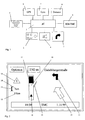
- FIG 1 are the essential components of an on-board navigation system shown.
- the central component of this system is the computing unit 1.
- An operating unit 2 is connected to the computing unit 1, via which a destination can be entered or selected. You can also use the control unit 2 further settings of the navigation system made become.
- the system continues to display visual information for driving instructions Output unit a screen 3, with a display on multiple screens is possible.
- a reader 5 is connected to the computing unit 1, which for Reading of map data from a storage medium and for forwarding the map data is designed for a memory of the computing unit 1.
- the map data are stored, for example, on a CD-ROM.
- Radio receiver 9 is provided, which also with the computing unit 1 is connected.
- traffic information received directly when calculating the route be taken into account or via the screen 3 or the acoustic output unit 4 to be transmitted to the driver.
- Radio receivers 9 can also use a GSM module or a mobile radio telephone be available to transmit the traffic information in the vehicle. In this respect it is a known navigation system, so that a further description of the individual components and their interaction is not necessary here.
- the traffic information received by the radio receiver 9 becomes evaluated in the computing unit 1 in a manner known per se. If there is traffic information regarding the intended route, then so is now the distance of the vehicle according to the invention from the computing unit 1 calculated at the beginning of the reported traffic obstruction. For this the vehicle position determined via GPS or dead reckoning is taken into account. Then the length of the reported traffic obstruction and the distance of the vehicle from the beginning of the traffic obstruction of the processing unit 1 processed into a diagram and on the screen 3 shown. An acoustic warning is preferably also given.
- a screen display according to the invention is shown by way of example in FIG.
- the information displayed on the screen includes, for example the information about the direction of travel and upcoming turning maneuvers the arrow representations 10, 11.
- a general symbol 12 which indicates a traffic obstruction on the indicates the planned route.
- Via a symbol 13 together with a length specification 14 shows the length of the traffic obstruction.
- the user will continue to know the current distance Vehicle position informed of the beginning of the traffic obstruction. It has It has been shown, however, that the driver only provides numerical values during the journey is relatively difficult to absorb and process. According to the invention is therefore still the representation of this information in one Histogram 16 is provided.
- the histogram points an area 17 which represents the traffic obstruction.
- the bar length area 17 is a measure of the length of the reported traffic obstruction.
- the current vehicle position is also in the histogram represented by a symbol 18.
- the distance of the symbol 18 from which the traffic obstruction representing area 17 is a measure of the distance of the vehicle from the beginning of the traffic obstruction.
- the driver can, for example, with a single glance at the screen display First, the length of the traffic obstruction based on the number 14 take up. The output can also be done acoustically. The The length of the traffic obstruction will generally only change slowly. Through the relation of the distance of your own vehicle from the traffic obstruction the length of the traffic obstruction in the diagram the driver also gets a very quick and always up-to-date overview of the distance to the beginning of the traffic disruption without this has to process further numbers.
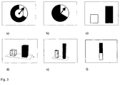
- FIG. 3 Various alternative diagram representations are shown by way of example in FIG shown that can be used according to the invention. These include the 3a and 3b shown ring and pie charts, in which the length the traffic obstruction, for example due to the dark sector and the Vehicle position can be represented by a pointer.
- Figure 3c a bar chart with bars arranged side by side, where the bar height the length of the traffic obstruction or the distance to symbolize the beginning of the traffic disruption.
- Figures 3d and 3e are corresponding three-dimensional representations in the form of cuboids or Cylinders shown.
- FIG. 3f shows a representation with one above the other Bars, where again the bar height is the length of the traffic obstruction or symbolizes the distance to the beginning of the traffic obstruction.
Landscapes
- Engineering & Computer Science (AREA)
- Radar, Positioning & Navigation (AREA)
- Remote Sensing (AREA)
- Automation & Control Theory (AREA)
- General Physics & Mathematics (AREA)
- Physics & Mathematics (AREA)
- Biodiversity & Conservation Biology (AREA)
- Environmental Sciences (AREA)
- Environmental & Geological Engineering (AREA)
- Ecology (AREA)
- Life Sciences & Earth Sciences (AREA)
- Atmospheric Sciences (AREA)
- Navigation (AREA)
- Traffic Control Systems (AREA)
Abstract
Description
- Fig. 1:
- die wesentlichen Komponenten eines on-board Navigationssystems,
- Fig. 2:
- eine Bildschirmdarstellung,
- Fig. 3:
- verschiedene Diagrammvarianten.
Claims (28)
- Navigationssystem für Kraftfahrzeuge mitMitteln zur Bestimmung der Fahrzeugposition (6; 7, 8),einer Eingabeeinheit (2) zur Eingabe eines Fahrziels,Mitteln zum Empfang von Verkehrsinformationen (9),einer Recheneinheit (1) zur Datenaufbereitung,einer optischen Ausgabeeinheit (3) zur graphischen Darstellung von Fahrhinweisen und die Fahrstrecke betreffende Verkehrsinformationen, die die Länge einer Verkehrsbehinderung beinhalten, dadurch gekennzeichnet, daß die Länge der Verkehrsbehinderung und der Abstand des Fahrzeugs zu einem in Zusammenhang mit der Verkehrsbehinderung markanten Punkt in einem Diagramm darstellbar sind.
- Navigationssystem nach Anspruch 1, dadurch gekennzeichnet, daß es sich bei dem Diagramm um ein Histogramm (16) handelt.
- Navigationssystem nach einem der vorhergehenden Ansprüche, dadurch gekennzeichnet, daß das Diagramm einen Hinweis zu einer Abzweigstelle (19) enthält und die Position des Hinweises in Relation zur Entfernung der Abweigstelle vom Beginn bzw. Ende der Verkehrsbehinderung angeordnet ist.
- Navigationssystem nach einem der vorhergehenden Ansprüche, dadurch gekennzeichnet, daß die Fahrhinweise symbolisch, insbesondere in Form von Pfeilen (10, 11), anzeigbar sind.
- Navigationssystem nach einem der vorhergehenden Ansprüche, dadurch gekennzeichnet, daß auf der Ausgabeeinheit in einem ersten Anzeigebereich das Diagramm und die symbolischen Fahrhinweise und in einem zweiten Anzeigebereich eine Straßenkarte darstellbar ist.
- Navigationssystem nach einem der vorhergehenden Ansprüche, dadurch gekennzeichnet, daß in der Recheneinheit (1) eine Routenberechnung durchführbar ist.
- Navigationssystem nach einem der vorhergehenden Ansprüche, dadurch gekennzeichnet, daß ein Lesegerät (5) zum Auslesen von auf einem Datenträger abgespeicherten Landkartendaten vorhanden ist.
- Navigationssystem nach einem der vorhergehenden Ansprüche, dadurch gekennzeichnet, daß das Navigationssystem zum Empfang von Landkartendaten ausgelegt ist, die von einer zentralen Sendestation ausgesendet werden.
- Navigationssystem nach einem der vorhergehenden Ansprüche, dadurch gekennzeichnet, daß ein Rundfunkempfänger (9) zum Empfang der Verkehrsinformationen vorhanden ist und die Verkehrsinformationen in der Recheneinheit (1) auswertbar sind.
- Navigationssystem nach einem der vorhergehenden Ansprüche, dadurch gekennzeichnet, daß es mit einem Mobilfunktelefon verbindbar ist, über das die Verkehrsinformationen empfangbar sind.
- Navigationssystem nach Anspruch 10, dadurch gekennzeichnet, daß über das Mobilfunktelefon auch Landkartendaten empfangbar sind.
- Navigationssystem nach einem der vorhergehenden Ansprüche, dadurch gekennzeichnet, daß über das Mobilfunktelefon eine von einem Zentralrechner berechnete Route empfangbar ist.
- Navigationssystem nach einem der vorhergehenden Ansprüche, dadurch gekennzeichnet, daß es eine akustische Ausgabeeinheit (4) enthält.
- Navigationssystem nach einem der vorhergehenden Ansprüche, dadurch gekennzeichnet, daß die Fahrzeugposition durch Koppelnavigation bestimmbar ist.
- Navigationssystem nach einem der vorhergehenden Ansprüche, dadurch gekennzeichnet, daß die Fahrzeugposition durch Satellitennavigation bestimmbar ist.
- Verfahren zur Aufbereitung von Verkehrsinformationen in einem Navigationssystem für Kraftfahrzeuge, wobeieine Fahrroute anhand eines eingegebenen Fahrziels berechnet wirddie Fahrzeugposition bestimmt wird,Verkehrsinformationen zu Verkehrsbehinderungen, die auch deren Länge beinhalten, empfangen werden,die Verkehrsinformationen in einer Recheneinheit hinsichtlich ihrer Relevanz für die berechnete Fahrroute ausgewertet werden,der Abstand des Fahrzeugs von einer auf der Fahrroute des Fahrzeugs liegenden Verkehrsbehinderung bestimmt wird,die Länge der Verkehrsbehinderung und der Abstand des Fahrzeugs zu einem in Zusammenhang mit der Verkehrsbehinderung markanten Punkt, insbesondere zum Anfang der Verkehrsbehinderung, in einem Diagramm auf einer optischen Ausgabeeinheit dargestellt wird.
- Verfahren nach Anspruch 16, dadurch gekennzeichnet, daß die Länge der Verkehrsbehinderung und der Abstand des Fahrzeugs vom Beginn der Verkehrsbehinderung in einem Histogramm dargestellt wird.
- Verfahren nach Anspruch 16 oder 17, dadurch gekennzeichnet, daß die Entfernung einer Abzweigstelle vom Beginn oder Ende der Verkehrsbehinderung berechnet wird und das Diagramm einen Hinweis auf diese Abzweigstelle enthält, wobei die Position des Hinweises auf die Abzweigstelle in Relation zur Entfernung der Abzweigstelle vom Beginn oder Ende der Verkehrsbehinderung angeordnet ist.
- Verfahren nach einem der vorhergehenden Ansprüche 16 bis 18, dadurch gekennzeichnet, daß auf der Ausgabeeinheit Fahrhinweise symbolisch, insbesondere in Form von Pfeilen, ausgegeben werden.
- Verfahren nach einem der vorhergehenden Ansprüche 16 bis 19, dadurch gekennzeichnet, daß auf der Ausgabeeinheit in einem ersten Anzeigebereich das Diagramm und die symbolischen Fahrhinweise und in einem zweiten Ausgabebereich eine Straßenkarte dargestellt werden.
- Verfahren nach einem der vorhergehenden Ansprüche 16 bis 20, dadurch gekennzeichnet, daß die Berechnung der Fahrroute in der Recheneinheit des Navigationssystem durchgeführt wird.
- Verfahren nach Anspruch 21, dadurch gekennzeichnet, daß die zur Berechnung der Fahrroute erforderlichen Landkartendaten von einem im Fahrzeug vorhandenen Lesegerät an die Recheneinheit übermittelt werden.
- Verfahren nach einem der vorhergehenden Ansprüche 16 bis 21, dadurch gekennzeichnet, daß die Landkartendaten von einem externen Sender in das Fahrzeug übermittelt werden.
- Verfahren nach einem der vorhergehenden Ansprüche 16 bis 23, dadurch gekennzeichnet, daß die Verkehrsinformationen über ein Rundfunksystem übermittelt werden.
- Verfahren nach einem der vorhergehenden Ansprüche 16 bis 24, dadurch gekennzeichnet, daß die Verkehrsinformationen über ein Mobilfunksystem übermittelt werden
- Verfahren nach einem der vorhergehenden Ansprüche 16 bis 25, dadurch gekennzeichnet, daß die Fahrroute in einem außerhalb des Fahrzeugs angeordneten Zentralrechner ermittelt und an das Navigationssystem übermittelt wird.
- Verfahren nach einem der vorhergehenden Ansprüche 16 bis 26, dadurch gekennzeichnet, daß die Fahrzeugposition durch Koppelnavigation ermittelt wird.
- Verfahren nach einem der vorhergehenden Ansprüche 16 bis 27, dadurch gekennzeichnet, daß die Fahrzeugposition durch Satellitennavigation ermittelt wird.
Applications Claiming Priority (2)
| Application Number | Priority Date | Filing Date | Title |
|---|---|---|---|
| DE1999153671 DE19953671A1 (de) | 1999-11-08 | 1999-11-08 | Navigationssystem |
| DE19953671 | 1999-11-08 |
Publications (3)
| Publication Number | Publication Date |
|---|---|
| EP1098171A2 true EP1098171A2 (de) | 2001-05-09 |
| EP1098171A3 EP1098171A3 (de) | 2004-07-07 |
| EP1098171B1 EP1098171B1 (de) | 2011-01-26 |
Family
ID=7928284
Family Applications (1)
| Application Number | Title | Priority Date | Filing Date |
|---|---|---|---|
| EP20000123634 Expired - Lifetime EP1098171B1 (de) | 1999-11-08 | 2000-10-30 | Navigationssytem |
Country Status (2)
| Country | Link |
|---|---|
| EP (1) | EP1098171B1 (de) |
| DE (2) | DE19953671A1 (de) |
Cited By (1)
| Publication number | Priority date | Publication date | Assignee | Title |
|---|---|---|---|---|
| WO2020025308A1 (de) * | 2018-08-03 | 2020-02-06 | Bayerische Motoren Werke Aktiengesellschaft | Fahrerassistenzsystem für ein kraftfahrzeug |
Families Citing this family (2)
| Publication number | Priority date | Publication date | Assignee | Title |
|---|---|---|---|---|
| DE10200759A1 (de) * | 2002-01-10 | 2003-08-14 | Daimler Chrysler Ag | Verfahren und System zur dynamischen Zielführung |
| DE10200758A1 (de) * | 2002-01-10 | 2003-11-13 | Daimler Chrysler Ag | Verfahren und System zur Zielführung von Fahrzeugen |
Family Cites Families (8)
| Publication number | Priority date | Publication date | Assignee | Title |
|---|---|---|---|---|
| JP2798934B2 (ja) * | 1988-08-23 | 1998-09-17 | アイシン・エィ・ダブリュ株式会社 | ナビゲーション装置 |
| JP2995687B2 (ja) * | 1990-06-06 | 1999-12-27 | マツダ株式会社 | 車両用ナビゲーション装置 |
| DE4429121C1 (de) * | 1994-08-17 | 1996-02-22 | Siemens Ag | Navigationssystem für ein Fahrzeug |
| JP3483672B2 (ja) * | 1995-09-06 | 2004-01-06 | 三菱電機株式会社 | ナビゲーション装置 |
| JP3408035B2 (ja) * | 1995-11-17 | 2003-05-19 | 松下電器産業株式会社 | 道路交通情報表示方法および道路交通情報表示装置 |
| FR2743176B1 (fr) * | 1996-01-03 | 1998-02-13 | Carte Blanche Conseil | Systeme d'aide a la navigation |
| US6185503B1 (en) * | 1996-05-31 | 2001-02-06 | Xanavi Informatics Corporation | Navigation system |
| JP3698835B2 (ja) * | 1996-10-25 | 2005-09-21 | 三菱電機株式会社 | 交通情報表示装置及びその表示方法並びに交通情報表示装置用表示制御プログラムを記録した媒体 |
-
1999
- 1999-11-08 DE DE1999153671 patent/DE19953671A1/de not_active Withdrawn
-
2000
- 2000-10-30 EP EP20000123634 patent/EP1098171B1/de not_active Expired - Lifetime
- 2000-10-30 DE DE50016067T patent/DE50016067D1/de not_active Expired - Lifetime
Cited By (1)
| Publication number | Priority date | Publication date | Assignee | Title |
|---|---|---|---|---|
| WO2020025308A1 (de) * | 2018-08-03 | 2020-02-06 | Bayerische Motoren Werke Aktiengesellschaft | Fahrerassistenzsystem für ein kraftfahrzeug |
Also Published As
| Publication number | Publication date |
|---|---|
| DE50016067D1 (de) | 2011-03-10 |
| DE19953671A1 (de) | 2001-05-10 |
| EP1098171B1 (de) | 2011-01-26 |
| EP1098171A3 (de) | 2004-07-07 |
Similar Documents
| Publication | Publication Date | Title |
|---|---|---|
| DE3880689T2 (de) | Navigationsvorrichtung. | |
| DE19716096C2 (de) | Verkehrsinformations-Anzeigeeinheit | |
| DE102007038464B4 (de) | Verfahren zum Betrieb einer Einrichtung zur Ermittlung eines Streckenverlaufes für ein Fortbewegungsmittel | |
| DE4034681C2 (de) | ||
| EP1636550A1 (de) | Navigationssystem mit fahrspurhinweisen | |
| DE102008019630B4 (de) | Fahrzeuginterne Kartenanzeigevorrichtung, Kartenanzeigeverfahren | |
| EP0942403B1 (de) | Verfahren und Vorrichtung zur Darstellung von Informationen für ein Navigationsgerät | |
| DE102008062012B4 (de) | Navigationsgerät | |
| WO2006037360A1 (de) | Fahrerinformationssystem zur information über die durchführbarkeit von überholvorgängen | |
| WO1997018544A2 (de) | Verfahren und zielführungseinheit zur sicheren zielführung eines fahrzeugs | |
| DE102009027535A1 (de) | Vorrichtung zur Unterstützung eines Einschervorgangs bei Fahrzeugen | |
| EP3649434B1 (de) | Verfahren und vorrichtung zum anzeigen von spurinformationen in einem fahrzeug | |
| EP1533592B1 (de) | Verfahren zur Auswahl und Aufbereitung von Verkehrsinformationen | |
| DE19600700B4 (de) | Navigationsgerät | |
| DE19725075A1 (de) | Einrichtung zur Bereitstellung von Informationen über die jeweils vorgegebene Höchstgeschwindigkeit in einem Kraftfahrzeug | |
| DE10258161B4 (de) | Fahrzeugnavigationssystem und diesbezügliches Verfahren | |
| EP0715289A2 (de) | Verfahren und System zur Zielführung eines Fahrzeugs | |
| EP1389728B1 (de) | Fahrerinformationsvorrichtung | |
| DE19531822A1 (de) | Verfahren und Anzeigevorrichtung zur Zielführung eines Fahrzeugs | |
| EP1098171B1 (de) | Navigationssytem | |
| EP0849563B1 (de) | System zur bewerteten Fahrtroutenoptimierung | |
| EP1136791A1 (de) | Verfahren und Vorrichtung zur Darstellung eines geografischen Bildes auf einem Bildschirm | |
| DE69808643T2 (de) | Navigationsanlage für kraftfahrzeuge | |
| DE602004009975T2 (de) | Fahrerassistenzsystem für Kraftfahrzeuge | |
| DE69815152T2 (de) | Navigationshilfsvorrichtung in einem system an bord eines fahrzeugs |
Legal Events
| Date | Code | Title | Description |
|---|---|---|---|
| PUAI | Public reference made under article 153(3) epc to a published international application that has entered the european phase |
Free format text: ORIGINAL CODE: 0009012 |
|
| AK | Designated contracting states |
Kind code of ref document: A2 Designated state(s): AT BE CH CY DE DK ES FI FR GB GR IE IT LI LU MC NL PT SE |
|
| AX | Request for extension of the european patent |
Free format text: AL;LT;LV;MK;RO;SI |
|
| RAP1 | Party data changed (applicant data changed or rights of an application transferred) |
Owner name: SIEMENS AKTIENGESELLSCHAFT |
|
| PUAL | Search report despatched |
Free format text: ORIGINAL CODE: 0009013 |
|
| AK | Designated contracting states |
Kind code of ref document: A3 Designated state(s): AT BE CH CY DE DK ES FI FR GB GR IE IT LI LU MC NL PT SE |
|
| AX | Request for extension of the european patent |
Extension state: AL LT LV MK RO SI |
|
| 17P | Request for examination filed |
Effective date: 20040819 |
|
| AKX | Designation fees paid |
Designated state(s): DE FR GB |
|
| RAP1 | Party data changed (applicant data changed or rights of an application transferred) |
Owner name: CONTINENTAL AUTOMOTIVE GMBH |
|
| 17Q | First examination report despatched |
Effective date: 20080505 |
|
| GRAP | Despatch of communication of intention to grant a patent |
Free format text: ORIGINAL CODE: EPIDOSNIGR1 |
|
| GRAS | Grant fee paid |
Free format text: ORIGINAL CODE: EPIDOSNIGR3 |
|
| GRAA | (expected) grant |
Free format text: ORIGINAL CODE: 0009210 |
|
| AK | Designated contracting states |
Kind code of ref document: B1 Designated state(s): DE FR GB |
|
| REG | Reference to a national code |
Ref country code: GB Ref legal event code: FG4D Free format text: NOT ENGLISH |
|
| REF | Corresponds to: |
Ref document number: 50016067 Country of ref document: DE Date of ref document: 20110310 Kind code of ref document: P |
|
| REG | Reference to a national code |
Ref country code: DE Ref legal event code: R096 Ref document number: 50016067 Country of ref document: DE Effective date: 20110310 |
|
| PLBE | No opposition filed within time limit |
Free format text: ORIGINAL CODE: 0009261 |
|
| STAA | Information on the status of an ep patent application or granted ep patent |
Free format text: STATUS: NO OPPOSITION FILED WITHIN TIME LIMIT |
|
| 26N | No opposition filed |
Effective date: 20111027 |
|
| REG | Reference to a national code |
Ref country code: DE Ref legal event code: R097 Ref document number: 50016067 Country of ref document: DE Effective date: 20111027 |
|
| PGFP | Annual fee paid to national office [announced via postgrant information from national office to epo] |
Ref country code: GB Payment date: 20121019 Year of fee payment: 13 |
|
| GBPC | Gb: european patent ceased through non-payment of renewal fee |
Effective date: 20131030 |
|
| PG25 | Lapsed in a contracting state [announced via postgrant information from national office to epo] |
Ref country code: GB Free format text: LAPSE BECAUSE OF NON-PAYMENT OF DUE FEES Effective date: 20131030 |
|
| REG | Reference to a national code |
Ref country code: DE Ref legal event code: R084 Ref document number: 50016067 Country of ref document: DE |
|
| REG | Reference to a national code |
Ref country code: DE Ref legal event code: R084 Ref document number: 50016067 Country of ref document: DE Effective date: 20150327 |
|
| REG | Reference to a national code |
Ref country code: FR Ref legal event code: PLFP Year of fee payment: 16 |
|
| REG | Reference to a national code |
Ref country code: FR Ref legal event code: PLFP Year of fee payment: 17 |
|
| PGFP | Annual fee paid to national office [announced via postgrant information from national office to epo] |
Ref country code: DE Payment date: 20161031 Year of fee payment: 17 |
|
| REG | Reference to a national code |
Ref country code: FR Ref legal event code: PLFP Year of fee payment: 18 |
|
| PGFP | Annual fee paid to national office [announced via postgrant information from national office to epo] |
Ref country code: FR Payment date: 20171024 Year of fee payment: 18 |
|
| REG | Reference to a national code |
Ref country code: DE Ref legal event code: R119 Ref document number: 50016067 Country of ref document: DE |
|
| PG25 | Lapsed in a contracting state [announced via postgrant information from national office to epo] |
Ref country code: DE Free format text: LAPSE BECAUSE OF NON-PAYMENT OF DUE FEES Effective date: 20180501 |
|
| PG25 | Lapsed in a contracting state [announced via postgrant information from national office to epo] |
Ref country code: FR Free format text: LAPSE BECAUSE OF NON-PAYMENT OF DUE FEES Effective date: 20181031 |