EP1097828A2 - Heiz/Verdampfereinheit für Kraftfahrzeug-Innenraum - Google Patents
Heiz/Verdampfereinheit für Kraftfahrzeug-Innenraum Download PDFInfo
- Publication number
- EP1097828A2 EP1097828A2 EP00309894A EP00309894A EP1097828A2 EP 1097828 A2 EP1097828 A2 EP 1097828A2 EP 00309894 A EP00309894 A EP 00309894A EP 00309894 A EP00309894 A EP 00309894A EP 1097828 A2 EP1097828 A2 EP 1097828A2
- Authority
- EP
- European Patent Office
- Prior art keywords
- housing body
- heater unit
- heater
- frame
- internal
- Prior art date
- Legal status (The legal status is an assumption and is not a legal conclusion. Google has not performed a legal analysis and makes no representation as to the accuracy of the status listed.)
- Withdrawn
Links
Images


Classifications
-
- B—PERFORMING OPERATIONS; TRANSPORTING
- B60—VEHICLES IN GENERAL
- B60H—ARRANGEMENTS OF HEATING, COOLING, VENTILATING OR OTHER AIR-TREATING DEVICES SPECIALLY ADAPTED FOR PASSENGER OR GOODS SPACES OF VEHICLES
- B60H1/00—Heating, cooling or ventilating devices
- B60H1/00007—Combined heating, ventilating, or cooling devices
- B60H1/00021—Air flow details of HVAC devices
- B60H1/00028—Constructional lay-out of the devices in the vehicle
-
- B—PERFORMING OPERATIONS; TRANSPORTING
- B29—WORKING OF PLASTICS; WORKING OF SUBSTANCES IN A PLASTIC STATE IN GENERAL
- B29C—SHAPING OR JOINING OF PLASTICS; SHAPING OF MATERIAL IN A PLASTIC STATE, NOT OTHERWISE PROVIDED FOR; AFTER-TREATMENT OF THE SHAPED PRODUCTS, e.g. REPAIRING
- B29C49/00—Blow-moulding, i.e. blowing a preform or parison to a desired shape within a mould; Apparatus therefor
-
- B—PERFORMING OPERATIONS; TRANSPORTING
- B60—VEHICLES IN GENERAL
- B60H—ARRANGEMENTS OF HEATING, COOLING, VENTILATING OR OTHER AIR-TREATING DEVICES SPECIALLY ADAPTED FOR PASSENGER OR GOODS SPACES OF VEHICLES
- B60H1/00—Heating, cooling or ventilating devices
- B60H1/00507—Details, e.g. mounting arrangements, desaeration devices
- B60H1/00514—Details of air conditioning housings
-
- B—PERFORMING OPERATIONS; TRANSPORTING
- B29—WORKING OF PLASTICS; WORKING OF SUBSTANCES IN A PLASTIC STATE IN GENERAL
- B29C—SHAPING OR JOINING OF PLASTICS; SHAPING OF MATERIAL IN A PLASTIC STATE, NOT OTHERWISE PROVIDED FOR; AFTER-TREATMENT OF THE SHAPED PRODUCTS, e.g. REPAIRING
- B29C49/00—Blow-moulding, i.e. blowing a preform or parison to a desired shape within a mould; Apparatus therefor
- B29C49/08—Biaxial stretching during blow-moulding
- B29C49/16—Biaxial stretching during blow-moulding using pressure difference for pre-stretching, e.g. pre-blowing
- B29C49/1602—Biaxial stretching during blow-moulding using pressure difference for pre-stretching, e.g. pre-blowing pre-blowing without using a mould
-
- B—PERFORMING OPERATIONS; TRANSPORTING
- B29—WORKING OF PLASTICS; WORKING OF SUBSTANCES IN A PLASTIC STATE IN GENERAL
- B29C—SHAPING OR JOINING OF PLASTICS; SHAPING OF MATERIAL IN A PLASTIC STATE, NOT OTHERWISE PROVIDED FOR; AFTER-TREATMENT OF THE SHAPED PRODUCTS, e.g. REPAIRING
- B29C49/00—Blow-moulding, i.e. blowing a preform or parison to a desired shape within a mould; Apparatus therefor
- B29C49/42—Component parts, details or accessories; Auxiliary operations
- B29C49/4242—Means for deforming the parison prior to the blowing operation
-
- B—PERFORMING OPERATIONS; TRANSPORTING
- B29—WORKING OF PLASTICS; WORKING OF SUBSTANCES IN A PLASTIC STATE IN GENERAL
- B29C—SHAPING OR JOINING OF PLASTICS; SHAPING OF MATERIAL IN A PLASTIC STATE, NOT OTHERWISE PROVIDED FOR; AFTER-TREATMENT OF THE SHAPED PRODUCTS, e.g. REPAIRING
- B29C49/00—Blow-moulding, i.e. blowing a preform or parison to a desired shape within a mould; Apparatus therefor
- B29C49/42—Component parts, details or accessories; Auxiliary operations
- B29C49/48—Moulds
- B29C49/4802—Moulds with means for locally compressing part(s) of the parison in the main blowing cavity
- B29C49/4812—Moulds with means for locally compressing part(s) of the parison in the main blowing cavity and welding opposite wall parts of the parisons or preforms to each other
-
- B—PERFORMING OPERATIONS; TRANSPORTING
- B29—WORKING OF PLASTICS; WORKING OF SUBSTANCES IN A PLASTIC STATE IN GENERAL
- B29L—INDEXING SCHEME ASSOCIATED WITH SUBCLASS B29C, RELATING TO PARTICULAR ARTICLES
- B29L2023/00—Tubular articles
- B29L2023/004—Bent tubes
-
- B—PERFORMING OPERATIONS; TRANSPORTING
- B29—WORKING OF PLASTICS; WORKING OF SUBSTANCES IN A PLASTIC STATE IN GENERAL
- B29L—INDEXING SCHEME ASSOCIATED WITH SUBCLASS B29C, RELATING TO PARTICULAR ARTICLES
- B29L2031/00—Other particular articles
- B29L2031/30—Vehicles, e.g. ships or aircraft, or body parts thereof
-
- B—PERFORMING OPERATIONS; TRANSPORTING
- B60—VEHICLES IN GENERAL
- B60H—ARRANGEMENTS OF HEATING, COOLING, VENTILATING OR OTHER AIR-TREATING DEVICES SPECIALLY ADAPTED FOR PASSENGER OR GOODS SPACES OF VEHICLES
- B60H1/00—Heating, cooling or ventilating devices
- B60H1/00007—Combined heating, ventilating, or cooling devices
- B60H1/00021—Air flow details of HVAC devices
- B60H2001/00078—Assembling, manufacturing or layout details
- B60H2001/00107—Assembling, manufacturing or layout details characterised by the relative position of the heat exchangers, e.g. arrangements leading to a curved airflow
Definitions
- This invention relates to a heater/evaporator unit for use with a motor vehicle passenger compartment.
- Motor vehicle passenger compartments are normally heated and/or cooled by a heater and/or evaporator unit, referred to herein for convenience simply as a "heater unit”.
- the heater unit normally comprises a housing body through which air is made to circulate. Internal walls and pivoting flaps are normally used to guide the air through the housing body, so that the air passes through an evaporator element and a heater element within the housing body.
- the wall thickness of the housing must be about 2 mm in order to provide the required strenght. This can make the housing unit heavy, whereas an important consideration in the design of vehicle is to keep the weight of component parts to a minimum.
- the housing body is conventionally made from injection moulded plastics material, and is usually made in two halves which then have to be screwed together.
- the halves will normally have one or more upstanding surfaces which meet to form interior walls when the halves are brought together. Due to tolerance limits, undesirably air leaks can result where the two halves meet, particularly along the line or lines between different sections of interior wall.
- a heater unit for a motor vehicle comprising a plastics material housing body and a structural frame surrounding and supporting the housing body, characterised in that the housing body is a unitary moulding having at least one air inlet and at least one air outlet with at least one chamber therebetween.
- the unitary moulding reduces the likelihood of a leak occurring at the junction where separate parts would otherwise be jointed together to form the housing body.
- the unitary moulding of the housing body is formed by blow moulding. Since the structural frame will provide support for the housing body, the wall thickness of the unitary can be reduced, for example by making it by blow moulding, thereby making the housing unit lighter.
- the housing will comprise internal walls that are also part of the unitary moulding, for example being formed by blow moulding. These internal walls will help guide the movement of air as it passes through the housing body.
- the internal-facing ends of the internal walls will preferably be radiused in order to reduce the turbulence of the air as is passes through the housing body. Reducing turbulence reduces the pressure difference across the housing body and hence increases the air flow.
- the internal walls will be hollow. This will allow width of the internal walls to be increased (and thereby also increase the radius of curvature of their internal facing edges) without substantially increasing the weight of the internal walls.
- the internal walls will preferably be curved in one direction, such that the radius of curvature lies in a single plane.
- the direction of curvature can be chosen to be in the same direction as the air flow through the housing body in order to further reduce turbulence.
- the housing body will preferably comprise a plurality of openings. Such openings may be used to provide an inlet and outlet to the housing body, or may be used to insert internal components into the housing body, such as a heater.
- the frame will preferably comprise a plurality of receiving features for engaging or otherwise receiving the end portions of internal components located within the housing body and supporting the weight of the components.
- Such receiving features may take the form of a pair of shaped loops located on opposite sides of the frame.
- the receiving features may take the form of shaped portions or shaped covers removably attached to the frame.
- Some or all of the receiving features may take the form of a plurality of hollow shaft portions for pivotally securing one or more axles to the frame, so that the frame bears the load of the axle and therefore that of any components joined to the axle such as a door. Openings in the housing body will preferably be provided to pass the pivot axle through the external walls, such that the axle makes direct contact with the hollow shaft portion, whose inner surface will act as a bearing for the axle.
- a portion of the external wall of the housing body make take the form of the receiving feature, such that when the internal component is received in the feature, the wall of the housing body is interposed between the receiving feature and the internal component.
- the housing body may be held within the frame by internal components within the housing body that are engaged with, received in or otherwise connected to the frame.
- the housing body will preferably be connected to the frame at one or more securing points. Screws or bolts may be used to secure the housing body to the frame at these points.
- FIGS 1 and 2 show a heater unit 10 with a plastics material blow moulded housing body 12 surrounded by a plastic material injection moulded structural frame 14.
- Fresh air enters the heater unit 10 through an inlet opening 16, and is guided (in part) by internal walls 18,20,21 formed integrally with the housing body 12 to one or both of two outlets 30,130.
- the air entering the heater unit 10 is first dried by passing through an evaporator 24 shown in dashed outline, and is subsequently directed by a pivoting main door 22 either to a heater 26 shown in dashed outline, or directly to one of the outlet openings 30,130, depending on the position of the main door 22.
- Other outlet section doors 122,222 are used to select one or both of the two outlets 30,130.
- the shape of the air chamber within the heater unit 10 is defined by the internal walls of the heater unit 12, the locations of the inlet and outlets openings 16,30,130 and the positions of the pivoting doors 22,122,222.
- the frame 14 is adapted to bear the weight of the main internal components within the heater unit 10, such as the doors 22,122,222 the heater 26 and the evaporator 24.
- the external walls of the housing body 12 are about 0.6 mm in thickness, and are consequently relatively weak.
- the frame comprises two pairs of loops 27,127 one loop from each pair on each opposite side of the frame 14, such that the evaporator 24 and the heater 26 are each supported by the frame when these are placed within the housing body between the loops 27,127.
- the housing body has on one or both sides two apertures 124,126 to allow for respectively the evaporator 24 and the heater 26 to be inserted into the housing body. These apertures 124,126 are then covered by sealing plates 7,107 affixed to the frame 14. The ends of the evaporator 24 and heater 26 passing through the loops 27,127 are retained by cupped projections formed by the sealing plates 7,107 and by similar projections integral with the housing body 12 on the far side of the housing as viewed in Figure 1.
- Each door 22,122,222 has a pivot axle 19,119,219 that runs through openings in the housing body 12 and is received at each end within a hollow cylindrical bearing 17,117,217 within the frame 14, such that each pivot axle 19,119,219 is able to rotate between the bearings 17,117,217 in order allow the door to pivot. In this way, the weight of each door 22,122,222 is born by the frame 14 rather than the housing 12, which as mentioned above, is relatively weak.
- Each axle 19,119,219 is prevented from moving laterally with respect to the frame 14 by a bolt 15,115,215 at one end and at the other end by a lever 13 (only one of which is shown) that has a hollow shaft 113 attached to the axle 19.
- the bolts 15,115,215 and the levers 13 are situated on the outside of the frame 14. Since the axles 19,119,219 run through openings in the housing, this method of securing the axles to the frame also serves to secure the housing body 12 to the frame 14.
- the internal walls 18,20,21 each have two surfaces, denoted with the suffix a or b respectively.
- the surfaces do not touch each other and in this example the walls are hollow, the gap within each wall being denoted by the suffix c.
- the frame 14 and the housing body 12 are formed separately, the frame being formed by injection moulding, in two parts which are subsequently assembled around the housing 12 and held together at a plurality of fixing points 32.
- the housing is formed by a blow moulding process that is adapted for the formation of internal walls.
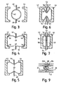
- An example of this process will now be described with reference to Figures 3 to 7, where the formation of an article shaped in only two directions is shown.
- Figure 3 shows a parison 40 which has been pre-blown to a generally cylindrical form and which is arranged between two mould parts 42 and 44 which are in an open, spaced apart, position. At either side of the mould there are retractable cores 46 and 48 in the form of flat plates with rounded leading edges 49.
- the parison 40 is fully blown into contact with the internal surfaces of the mould parts 42 and 44.
- the spacing between the mould parts at this time and the thickness of the parison walls will be chosen so that this position can be reached without the unsupported parts of the parison walls over inflating. It will be seen that in this position the parison walls make light, but not complete, contact with the mould parts and that there are void areas (indicated at 50) where the parison has not yet fully taken up the form of the mould parts.
- FIG 6 shows the stage in which the moulding is nearly completed.
- the mould parts 42, 44 have approached one another still further and the retractable cores 46, 48 have also approached one another still further.
- the cores 46, 48 are in the form of plates that flare out with radiused shoulders 56,57 towards bases 52, 54.
- the mould parts 42, 44 seat against the bases 52, 54 and the radiused shoulders 56,57 between the plates and the bases 52,54 form the junction between the cores 46,48 and the internal mould surfaces.
- Figure 7 shows the last stage in moulding where the product has two chambers 58, 59 which are separated by what has become a single internal moulded wall 34.
- the internal form of the mould parts is a very simple shape.
- three or more mould parts will be used and the mould parts will have a more complicated internal shape necessary to form the shape of the housing 12.
- the cores 46,48 will be inserted and retracted in a direction that is normal to the page in Figure 2. Because the internal walls 18,20,21 are curved, the cores will also be curved, the curvature being in a direction normal to the direction in which the cores move during the moulding process.
- Each internal wall 18,20,21 is formed by two cores that move towards one another from opposite sides of the housing 12 as it is being formed.
- the rounded leading edges of the cores will not be straight, and when the cores meet, a narrow gap will remain between the leading edges over most of their length.
- the webs extend perpendicularly between the two sides 18a,18b; 20a,20b; 21a,21b of each respective internal wall. Close to the outside ends of the internal walls, the leading edges of the cores come into direct contact when they meet, thereby clipping off the ends of the webs 18d,20d,21d.
- the webs 18d,20d,21d provide some structural linkage between portions of the housing separated by an internal wall.
- a hole can be provided in one or more of the webs in order to provide one or more securing points for one or more arms 33 of the frame 14 extending into the hollow area of the internal walls.
- the housing body 12 will be moulded with a closed exterior surface having protrusions known as lost heads extending across areas for evaporator and heater openings 124,126, the inlet opening 16, the outlet openings 30,130 are to be made in the housing 12 body.
- the openings will then be formed by cutting away these protrusions, either when the housing 12 is within the moulds 42,44 or after the housing 12 has been removed from the moulds.
- a unitary housing body 12 for a motor vehicle heater can be formed.
- a heater unit 10 is shown schematically in cross section.
- An expanded view of the region within the dotted circle is shown in Figure 9.
- the cross section of the heater unit in Figure 8 displays different aspects of the heater unit of Figures 1 and 2 in a single cross section, and does not represent a planar cross section through Figures 1 and 2.
- the frame 14 had a shaped feature 65 to receive one end 24a of an elongate evaporator 24, and the other end of the evaporator 24b is held in place by a cover 7, shaped so that its internal face accepts the end 24b of the evaporator.
- a sheet of foam 51 is located between the ends 24a,b of the evaporator and the frame/cover in order to prevent significant vibration of the evaporator 24 when it is in place in the heater unit 10.
- An opening 124 is provided in the housing body 12 to insert the evaporator during fabrication.
- the housing body 12 Only one opening 124 in the housing body 12 is provided to insert the evaporator 24.
- the housing body 12 On the opposite side of the housing body 12, the housing body 12 has a shaped portion 9 which conforms to the shape of one end 24a of the evaporator 24.
- the shaped portion 9 of the housing body 12 is received in the receiving feature 65 of the frame 14, so that when the end 24a of the evaporator 24 is received by the receiving feature 65, the shaped portion 9 of the housing wall is interposed between receiving feature 65 and the evaporator end 24a. This removes the need for an additional opening in the wall of the housing body 12.
- an internal wall 20 is shown, with surfaces 20a and 20b, separated by a gap 20c.
- a web 20d extends between the two wall surfaces 20a and 20b.
- arms 33 of the frame 14 extend into the gap 20c from both sides of the web 20d, and the ends of the arms 33 are secured together though a hole 68 in the web 20d, by a bolt 61 such that the hole 68 in the web 20d provides a securing point where the housing body 12 is secured to the frame 14.
- the door axle 19 is shown extending into a bearings 17 formed integrally with the casing.
- the axis is secured at each end by a bolt 15 and a lever 17 respectively.
- the invention provides a heater unit with a strong but light weight housing.
Landscapes
- Engineering & Computer Science (AREA)
- Mechanical Engineering (AREA)
- Physics & Mathematics (AREA)
- Thermal Sciences (AREA)
- Manufacturing & Machinery (AREA)
- Air-Conditioning For Vehicles (AREA)
Applications Claiming Priority (2)
| Application Number | Priority Date | Filing Date | Title |
|---|---|---|---|
| GB9926269 | 1999-11-08 | ||
| GB9926269A GB2356046A (en) | 1999-11-08 | 1999-11-08 | Air conditioning unit for a motor vehicle passenger compartment |
Publications (2)
| Publication Number | Publication Date |
|---|---|
| EP1097828A2 true EP1097828A2 (de) | 2001-05-09 |
| EP1097828A3 EP1097828A3 (de) | 2003-05-28 |
Family
ID=10864045
Family Applications (1)
| Application Number | Title | Priority Date | Filing Date |
|---|---|---|---|
| EP00309894A Withdrawn EP1097828A3 (de) | 1999-11-08 | 2000-11-07 | Heiz/Verdampfereinheit für Kraftfahrzeug-Innenraum |
Country Status (3)
| Country | Link |
|---|---|
| US (1) | US20030136856A1 (de) |
| EP (1) | EP1097828A3 (de) |
| GB (1) | GB2356046A (de) |
Cited By (5)
| Publication number | Priority date | Publication date | Assignee | Title |
|---|---|---|---|---|
| FR2854104A1 (fr) * | 2003-04-28 | 2004-10-29 | Valeo Climatisation | Dispositif de chauffage-ventilation et/ou climatisation de v vehicule automobile avec distribution d'air a l'interieur de l'habitacle. |
| US6925825B2 (en) | 2001-07-23 | 2005-08-09 | Mitsubishi Heavy Industries, Ltd. | Vehicle air-conditioning system |
| DE102009021178A1 (de) | 2008-05-14 | 2009-11-19 | Behr Gmbh & Co. Kg | Heizungs- und/oder Klimaanlagengehäuse aus Kunststoff |
| DE102008002408A1 (de) | 2008-06-12 | 2009-12-17 | Visteon Global Technologies, Inc., Van Buren Township | Gehäuse für ein Heiz- und Klimagerät von Kraftfahrzeugen sowie Verfahren zu seiner Herstellung |
| EP2944487A1 (de) * | 2014-05-15 | 2015-11-18 | MAHLE International GmbH | Leichtgewichtiges hlk-modul |
Family Cites Families (2)
| Publication number | Priority date | Publication date | Assignee | Title |
|---|---|---|---|---|
| HU180201B (en) * | 1978-10-06 | 1983-02-28 | Schultz Gmbh Aurora | Device for heating and ventilating vehicles |
| GB2217440A (en) * | 1988-04-13 | 1989-10-25 | Ford Motor Co | A heater box |
-
1999
- 1999-11-08 GB GB9926269A patent/GB2356046A/en not_active Withdrawn
-
2000
- 2000-11-07 EP EP00309894A patent/EP1097828A3/de not_active Withdrawn
-
2003
- 2003-02-24 US US10/373,431 patent/US20030136856A1/en not_active Abandoned
Non-Patent Citations (1)
| Title |
|---|
| None |
Cited By (6)
| Publication number | Priority date | Publication date | Assignee | Title |
|---|---|---|---|---|
| US6925825B2 (en) | 2001-07-23 | 2005-08-09 | Mitsubishi Heavy Industries, Ltd. | Vehicle air-conditioning system |
| FR2854104A1 (fr) * | 2003-04-28 | 2004-10-29 | Valeo Climatisation | Dispositif de chauffage-ventilation et/ou climatisation de v vehicule automobile avec distribution d'air a l'interieur de l'habitacle. |
| DE102009021178A1 (de) | 2008-05-14 | 2009-11-19 | Behr Gmbh & Co. Kg | Heizungs- und/oder Klimaanlagengehäuse aus Kunststoff |
| DE102008002408A1 (de) | 2008-06-12 | 2009-12-17 | Visteon Global Technologies, Inc., Van Buren Township | Gehäuse für ein Heiz- und Klimagerät von Kraftfahrzeugen sowie Verfahren zu seiner Herstellung |
| DE102008002408B4 (de) | 2008-06-12 | 2022-03-24 | Hanon Systems | Gehäuse für ein Heiz- und Klimagerät eines Kraftfahrzeuges |
| EP2944487A1 (de) * | 2014-05-15 | 2015-11-18 | MAHLE International GmbH | Leichtgewichtiges hlk-modul |
Also Published As
| Publication number | Publication date |
|---|---|
| EP1097828A3 (de) | 2003-05-28 |
| US20030136856A1 (en) | 2003-07-24 |
| GB2356046A (en) | 2001-05-09 |
| GB9926269D0 (en) | 2000-01-12 |
Similar Documents
| Publication | Publication Date | Title |
|---|---|---|
| US6110037A (en) | Air conditioning duct device in automobile | |
| EP0728605B1 (de) | Entlüftungsklappe | |
| US6502897B2 (en) | Component for a motor vehicle | |
| US20030193207A1 (en) | Strength member for vehicle use | |
| JPH11165563A (ja) | 自動車の前部内装部品組立体 | |
| US7694729B2 (en) | Air passage opening/closing device | |
| EP1097828A2 (de) | Heiz/Verdampfereinheit für Kraftfahrzeug-Innenraum | |
| US11498413B2 (en) | Device for regulating an air stream for an air inlet of a motor vehicle | |
| FR2780347A1 (fr) | Boitier de chauffage et/ou climatisation de vehicule automobile a performances acoustiques ameliorees | |
| US4619073A (en) | Adjustable shutter assembly and method of making the same | |
| US6854794B2 (en) | Cross car duct with integrated mode doors and HVAC module | |
| US5722884A (en) | Flap for an air guiding duct | |
| US4286506A (en) | Air ventilation apparatus for vehicle | |
| US6552457B2 (en) | Support structure for drive source | |
| KR0139841B1 (ko) | 차량 실내용 통풍노즐 | |
| JP3985637B2 (ja) | 車両用空調装置 | |
| CN115071409A (zh) | 空气引导系统 | |
| JP4591805B2 (ja) | ケース伸長部材 | |
| JP2000219084A (ja) | 自動車用バックミラ― | |
| JPH10181359A (ja) | 自動車用ダッシュボードのための空気ダクト | |
| US6776444B2 (en) | Dashboard designed to be mounted in an interior of a vehicle, as well as to a vehicle body equipped with such a dashboard | |
| KR102111325B1 (ko) | 차량용 공조장치 | |
| JP4397099B2 (ja) | レゾネータ一体形ファンシュラウドおよび吸気ダクト付きレゾネータ一体形ファンシュラウド | |
| GB2217440A (en) | A heater box | |
| JP7538835B2 (ja) | 空調用吹出口装置 |
Legal Events
| Date | Code | Title | Description |
|---|---|---|---|
| PUAI | Public reference made under article 153(3) epc to a published international application that has entered the european phase |
Free format text: ORIGINAL CODE: 0009012 |
|
| AK | Designated contracting states |
Kind code of ref document: A2 Designated state(s): AT BE CH CY DE DK ES FI FR GB GR IE IT LI LU MC NL PT SE TR |
|
| AX | Request for extension of the european patent |
Free format text: AL;LT;LV;MK;RO;SI |
|
| PUAL | Search report despatched |
Free format text: ORIGINAL CODE: 0009013 |
|
| AK | Designated contracting states |
Designated state(s): AT BE CH CY DE DK ES FI FR GB GR IE IT LI LU MC NL PT SE TR |
|
| AX | Request for extension of the european patent |
Extension state: AL LT LV MK RO SI |
|
| 17P | Request for examination filed |
Effective date: 20030805 |
|
| 17Q | First examination report despatched |
Effective date: 20030922 |
|
| GRAP | Despatch of communication of intention to grant a patent |
Free format text: ORIGINAL CODE: EPIDOSNIGR1 |
|
| GRAP | Despatch of communication of intention to grant a patent |
Free format text: ORIGINAL CODE: EPIDOSNIGR1 |
|
| AKX | Designation fees paid |
Designated state(s): DE FR GB |
|
| STAA | Information on the status of an ep patent application or granted ep patent |
Free format text: STATUS: THE APPLICATION IS DEEMED TO BE WITHDRAWN |
|
| 18D | Application deemed to be withdrawn |
Effective date: 20040525 |