EP1097634B1 - Sitzstange für Geflügel - Google Patents
Sitzstange für Geflügel Download PDFInfo
- Publication number
- EP1097634B1 EP1097634B1 EP00114805A EP00114805A EP1097634B1 EP 1097634 B1 EP1097634 B1 EP 1097634B1 EP 00114805 A EP00114805 A EP 00114805A EP 00114805 A EP00114805 A EP 00114805A EP 1097634 B1 EP1097634 B1 EP 1097634B1
- Authority
- EP
- European Patent Office
- Prior art keywords
- perch
- poultry
- base
- profile
- animals
- Prior art date
- Legal status (The legal status is an assumption and is not a legal conclusion. Google has not performed a legal analysis and makes no representation as to the accuracy of the status listed.)
- Expired - Lifetime
Links
- 241000269799 Perca fluviatilis Species 0.000 title claims description 63
- 244000144977 poultry Species 0.000 claims description 38
- 238000013461 design Methods 0.000 claims description 3
- 210000003608 fece Anatomy 0.000 abstract description 40
- 241001465754 Metazoa Species 0.000 description 20
- 239000010871 livestock manure Substances 0.000 description 15
- 241000269800 Percidae Species 0.000 description 6
- 210000000078 claw Anatomy 0.000 description 5
- QGZKDVFQNNGYKY-UHFFFAOYSA-N Ammonia Chemical compound N QGZKDVFQNNGYKY-UHFFFAOYSA-N 0.000 description 4
- 238000011161 development Methods 0.000 description 3
- 230000000284 resting effect Effects 0.000 description 3
- 229910021529 ammonia Inorganic materials 0.000 description 2
- 238000009374 poultry farming Methods 0.000 description 2
- 210000003371 toe Anatomy 0.000 description 2
- 238000012549 training Methods 0.000 description 2
- 229910000831 Steel Inorganic materials 0.000 description 1
- 208000027418 Wounds and injury Diseases 0.000 description 1
- 238000009825 accumulation Methods 0.000 description 1
- XAGFODPZIPBFFR-UHFFFAOYSA-N aluminium Chemical compound [Al] XAGFODPZIPBFFR-UHFFFAOYSA-N 0.000 description 1
- 229910052782 aluminium Inorganic materials 0.000 description 1
- 238000013459 approach Methods 0.000 description 1
- 238000005452 bending Methods 0.000 description 1
- 230000008901 benefit Effects 0.000 description 1
- 230000015572 biosynthetic process Effects 0.000 description 1
- 230000008859 change Effects 0.000 description 1
- 230000006378 damage Effects 0.000 description 1
- 238000001035 drying Methods 0.000 description 1
- 230000005802 health problem Effects 0.000 description 1
- 208000015181 infectious disease Diseases 0.000 description 1
- 208000014674 injury Diseases 0.000 description 1
- 239000000463 material Substances 0.000 description 1
- 238000000034 method Methods 0.000 description 1
- 230000008569 process Effects 0.000 description 1
- 239000007787 solid Substances 0.000 description 1
- 239000010959 steel Substances 0.000 description 1
- 230000007704 transition Effects 0.000 description 1
Images
Classifications
-
- A—HUMAN NECESSITIES
- A01—AGRICULTURE; FORESTRY; ANIMAL HUSBANDRY; HUNTING; TRAPPING; FISHING
- A01K—ANIMAL HUSBANDRY; AVICULTURE; APICULTURE; PISCICULTURE; FISHING; REARING OR BREEDING ANIMALS, NOT OTHERWISE PROVIDED FOR; NEW BREEDS OF ANIMALS
- A01K31/00—Housing birds
- A01K31/04—Dropping-boards; Devices for removing excrement
-
- A—HUMAN NECESSITIES
- A01—AGRICULTURE; FORESTRY; ANIMAL HUSBANDRY; HUNTING; TRAPPING; FISHING
- A01K—ANIMAL HUSBANDRY; AVICULTURE; APICULTURE; PISCICULTURE; FISHING; REARING OR BREEDING ANIMALS, NOT OTHERWISE PROVIDED FOR; NEW BREEDS OF ANIMALS
- A01K31/00—Housing birds
- A01K31/12—Perches for poultry or birds, e.g. roosts
Definitions
- the invention relates to a perch designed as a profile for poultry.
- Perches for poultry are used, for example, in poultry houses arranged to be kept in this stall Poultry to create a lounge area.
- the Poultry can run on such a perch and sit, for example, during the night's sleep.
- Known perches are designed as symmetrical profiles. They have, for example, circular, rectangular or mushroom-shaped cross sections and are designed, for example, as hollow profiles or as solid profiles. Due to the symmetrical design of a known perch, the poultry can sit on the perch in two different sitting positions transverse to the longitudinal extent of the perch. This means that the sewers of poultry sitting on the perch are arranged on both sides of the perch. The sewers are thus disadvantageously arranged in a spatially wide area, so that a spatially wide zone is formed in which faeces are produced. If the poultry has a rest period on the perch, a large amount of feces is produced after this rest period.
- a manure is assigned to a manure collecting pit or manure collecting device, for example a manure collecting conveyor belt. This is preferably arranged below the perch so that it can catch droppings falling on the perch on the perch.
- the spatially wide zone in which faeces occur has the disadvantage that not all faeces are collected by the faeces collection device.
- the manure not collected by a manure collection device is therefore due to additional effort from the stable remove. This additional effort causes on disadvantageous cost.
- the invention has for its object a perch the genus mentioned at the outset, due to their constructive training in a simple way almost complete collection of the droppings with a droppings collector allows.
- This object is achieved in that at least one side of the profile forming the perch about straight and as a defined orientation of the seated poultry causing inclined plane is.
- the perch according to the invention has the constructive Peculiarity is that it is not a symmetrical profile is trained. Rather, it is a straight side of the profile designed as an inclined plane. This sloping level runs at an angle to the horizontal, the Perch is aligned so that the inclined plane is arranged on its top.
- the inclined plane of the perch causes advantageous An orientation of the sitting on the perch Poultry.
- This alignment is achieved that the poultry is sitting on the perch as a comfortable resting position, while it is in a Rotation through 180 ° does not find a comfortable resting position.
- To the the poultry takes an which can rest the chest on a wide area.
- the poultry will adopt such an orientation that it each had its chest sloping upward can lay on an inclined plane.
- the U-base forms the inclined plane and its U-leg are folded from the U-base.
- the invention Perch is designed as an open profile. This can be made easily, in short Time is, for example, through appropriate forming processes large quantities of U-profiles can be produced.
- As a material aluminum can be used for the perch Plastic or galvanized sheet steel are used. Through the Bending of U-legs from the U-base is at least an edge region of the perch formed behind the the poultry can grab with its claws.
- the inclined plane obliquely to the horizontal the U-legs run vertically downwards.
- One on the perched animal perches preferably with the front claws over the upper longitudinal edge of the through the U base formed oblique plane and reaches behind and under the assigned U-leg. To do one too high pressure load on claw areas of the animal avoid the fold areas between the U-base and U-legs are preferably rounded.
- the U-base is formed from two sections, the at different angles to the horizontal are. It is particularly provided that the front, upper section of the U base in a steeper Angle to the horizontal is set as the rear, lower section.
- This training has the advantage that the top section along with the vertically assigned, aligned U-legs an approximately symmetrical Forms partial profile.
- This section of the invention Profiles enables approaching, gripping and clawing of poultry sitting on this area of the profile.
- the upper section is guaranteed by the steep slope to the horizontal that the slope of the The surface remains and the animals sitting on it take the desired direction.
- the poultry reaches behind this section with his front toes, while the back toe to the lower longitudinal edge of the U base is approximated, but does not encompass it.
- the perch according to the invention can be used independently of others Plants within a barn arranged in this his. However, it is preferably provided that the invention Perch as a scaffold section in one framework-like poultry holder arrangement is used. scaffold-like Poultry farming arrangements are for example designed as floor systems, so-called "aviaries”. These tier systems offer the animals different levels of residence, where they can stay, drink and can eat. These are preferably different Levels of the floor systems according to the invention Assigned to perches. These perches serve at the same time as approach rods for the poultry. The poultry can over several, arranged on different levels Perches in the levels of the floor systems, for example two floor systems arranged opposite each other, move.
- the frame section formed by the perch preferably above one of the poultry farming arrangement assigned feces collecting device.
- the perch is above one Dung tape arranged slightly to the side of this can be offset. This ensures that Dung tape underneath the sewer defined on the perch is arranged aligned animals, so that almost all droppings are caught. Due to the The orientation of the animals can be the width of the manure belt to be kept relatively narrow. The costs for a wider manure collection belt are advantageously avoided. At the same time, it prevents feces from getting into one Poultry holder arrangement immediately adjacent bedding area arrives.
- the formation of the perch according to the invention brings about advantageously that they are in a border area between a manure collection device or a manure pit and a bedding area can be arranged without that there is a risk that feces in large quantities in the Litter area.
- the perch is used with her sloping plane arranged so that the sloping plane starting from that assigned to the manure collection device Area runs upwards at an angle. On the poultry barn sitting animals are due to the more comfortable position take a direction in which their sewers above the Excrement collecting device is arranged.
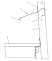
- the drawing shows a side view of a Perch for poultry in a poultry holder arrangement is arranged.
- the perch 1 is with fasteners, not shown on a vertically aligned strut 2 the scaffold-shaped poultry holder arrangement attached. Of the poultry holder arrangement is still a grid floor 3 is shown in one plane below the perch 1 also on the strut 2 is attached.
- the perch 1 is designed approximately as a U-profile.
- the U-base 4 of this profile forms an inclined plane out.
- the inclined plane runs approximately at an angle of 35 ° to the horizontal, starting from an area above the grid floor 3, runs diagonally upwards.
- the U base 4 is formed from two sections, those with different angles to the horizontal are employed.
- Above the grid floor 3 is a first section of the U-base 4 arranged, and in the area the strut 2 is arranged a second section of the U-base 4. This section arranged in the area of the strut 2 has a larger angle of inclination to the horizontal on than the other section.
- U-legs From the U-base 4 are U-legs in the area of their edges 5, 5 'edged. The fold areas between the U-base and the U-legs 5, 5 'are rounded. The U-leg 5 'has one in the direction of the U-leg 5 folded area 6, which is approximately parallel runs to U-base 4.
- a tongue 7 in a vertically aligned Beveled From the U-base 4 is a tongue 7 in a vertically aligned Beveled. With this tongue 7 can Perch 1 are attached to the strut 2. The perch 1 can be between adjacent struts a poultry holder arrangement, wherein in Area of each strut 2 a corresponding tongue 7 for attachment the perch 1 is provided. The tongue 7 is thus formed only in the area of a strut 2, it does not extend over the entire extent of the perch 1.
- the perch 1 can be approached by animals and can be used as a lounge area. Due to the sloping level of the perch 1 becomes perched poultry thereby brought into a defined orientation.
- the Poultry sits on the perch with one orientation 1, in which their sewers are arranged above the floor 3 are. Animals sitting the other way round can be found on the perch 1 not a comfortable hold so that they are in their sitting position turn by 180 °.
- a suitable feces collecting device can be found under the grid floor 3 can be arranged or it can be in place of the grid floor 3, a manure collection device can be provided. This takes the droppings from those on the perch 1 sitting animals falls down almost completely.
- the perch 1 can have a total width of approximately 100 mm exhibit.
- the section of the U base 4 with the lesser The slope is about 69 mm long while the other section is about 22 mm long.
- the rounded transition areas between the U base 4 and the U legs 5, 5 ' can have a radius of 5 mm.
- the free edges of the U-leg 5 and section 6 of the U-leg 5 ' are deburred to create a risk of injury to the rear these claw areas engaging on the perch To exclude 1 mounted animals.
Landscapes
- Life Sciences & Earth Sciences (AREA)
- Environmental Sciences (AREA)
- Birds (AREA)
- Zoology (AREA)
- Animal Husbandry (AREA)
- Biodiversity & Conservation Biology (AREA)
- Housing For Livestock And Birds (AREA)
- Catching Or Destruction (AREA)
- Compounds Of Unknown Constitution (AREA)
- Fodder In General (AREA)
Description
Zum Abtransport des anfallenden Kotes ist häufig vorgesehen, daß einer Sitzstange eine Kotsammelgrube oder eine Kotsammeleinrichtung, beispielsweise ein Kotsammelförderband zugeordnet ist. Dieses ist vorzugsweise unterhalb der Sitzstange angeordnet, so daß es von auf der Sitzstange aufsitzendem Geflügel herunterfallenden Kot auffangen kann. Durch die räumlich breite Zone, in der Kot anfällt, tritt der Nachteil auf, daß nicht sämtlicher Kot von der Kotsammeleinrichtung aufgefangen wird.
Claims (7)
- Als Profil ausgebildete Sitzstange (1) für Geflügel,
dadurch gekennzeichnet, daß wenigstens eine Seite des Profils etwa gerade und als eine definierte Ausrichtung des aufsitzenden Geflügels bewirkende schräge Ebene ausgebildet ist. - Sitzstange nach Anspruch 1, dadurch gekennzeichnet, daß die schräge Ebene in einem Winkel von ca. 35° zur Horizontalen angestellt ist.
- Sitzstange nach Anspruch 1 oder 2, dadurch gekennzeichnet, daß sie etwa als U-Profil ausgebildet ist, dessen U-Basis (4) die schräge Ebene ausbildet und dessen U-Schenkel (5, 5') von der U-Basis (4) abgekantet sind.
- Sitzstange nach Anspruch 3, dadurch gekennzeichnet, daß die U-Basis (4) aus zwei Abschnitten ausgebildet ist, die in voneinander verschiedenen Winkeln zur Horizontalen angestellt sind.
- Sitzstange nach Anspruch 3 oder 4, dadurch gekennzeichnet, daß die Abkantungsbereiche zwischen U-Basis (4) und U-Schenkeln (5, 5') jeweils abgerundet ausgebildet sind.
- Sitzstange nach einem der vorhergehenden Ansprüche, dadurch gekennzeichnet, daß sie als Gerüstabschnitt einer gerüstartigen Geflügelhalterungsanordnung ausgebildet ist.
- Sitzstange nach Anspruch 6, dadurch gekennzeichnet, daß der durch sie ausgebildete Gerüstabschnitt oberhalb einer der Geflügelhalterungsanordnung zugeordneten Kotsammeleinrichtung angeordnet ist.
Applications Claiming Priority (2)
| Application Number | Priority Date | Filing Date | Title |
|---|---|---|---|
| DE29919443U DE29919443U1 (de) | 1999-11-05 | 1999-11-05 | Sitzstange für Geflügel |
| DE29919443U | 1999-11-05 |
Publications (3)
| Publication Number | Publication Date |
|---|---|
| EP1097634A2 EP1097634A2 (de) | 2001-05-09 |
| EP1097634A3 EP1097634A3 (de) | 2001-08-29 |
| EP1097634B1 true EP1097634B1 (de) | 2002-12-11 |
Family
ID=8081210
Family Applications (1)
| Application Number | Title | Priority Date | Filing Date |
|---|---|---|---|
| EP00114805A Expired - Lifetime EP1097634B1 (de) | 1999-11-05 | 2000-07-11 | Sitzstange für Geflügel |
Country Status (5)
| Country | Link |
|---|---|
| US (1) | US6412439B1 (de) |
| EP (1) | EP1097634B1 (de) |
| AT (1) | ATE229266T1 (de) |
| DE (2) | DE29919443U1 (de) |
| ES (1) | ES2188461T3 (de) |
Cited By (1)
| Publication number | Priority date | Publication date | Assignee | Title |
|---|---|---|---|---|
| EP1570732A1 (de) | 2004-03-02 | 2005-09-07 | Big Dutchman International GmbH | Voliere zur Halterung von Geflügel |
Families Citing this family (18)
| Publication number | Priority date | Publication date | Assignee | Title |
|---|---|---|---|---|
| US9382070B2 (en) | 2012-10-24 | 2016-07-05 | Big Dutchman International Gmbh | Conveyor and method to convey animal products in an agricultural business |
| US11044892B2 (en) | 2013-11-04 | 2021-06-29 | Rose Acre Farms, Inc. | Aviary system and method of circulating litter in an aviary |
| US11041655B2 (en) | 2013-11-04 | 2021-06-22 | Rose Acre Farms, Inc. | Aviary ventilation system and method |
| US10130078B2 (en) | 2013-11-04 | 2018-11-20 | Rose Acre Farms, Inc. | Aviary cage with egg and manure removal system and method for constructing same |
| US10779513B2 (en) | 2013-11-04 | 2020-09-22 | Rose Acre Farms, Inc. | Aviary building construction system and method |
| US9723818B2 (en) | 2013-11-04 | 2017-08-08 | Rose Acre Farms, Inc. | Aviary cage with adjustable balcony |
| US9504234B2 (en) | 2013-11-04 | 2016-11-29 | Rose Acre Farms, Inc. | Egg saving perch and method |
| US10375935B2 (en) | 2013-11-04 | 2019-08-13 | Rose Acre Farms, Inc. | Aviary walkway and ventilation system and method of circulating air in an aviary |
| US9538731B2 (en) | 2014-03-18 | 2017-01-10 | Rose Acre Farms, Inc. | Aviary cage with manure removal system and method for constructing the same |
| US9307747B2 (en) | 2014-02-14 | 2016-04-12 | Rose Acre Farms, Inc. | Aviary cage |
| US10104872B2 (en) | 2014-02-14 | 2018-10-23 | Rose Acre Farms, Inc. | Cage-free aviary |
| DE202014007282U1 (de) | 2014-09-12 | 2015-12-16 | Big Dutchman International Gmbh | Dosiervorrichtung |
| EP3209121B1 (de) * | 2014-10-21 | 2019-04-17 | Officine Facco & C. S.p.A. | Volierenvorrichtung zur aufzucht von legehennen |
| US10412936B2 (en) | 2016-02-12 | 2019-09-17 | Rose Acre Farms, Inc. | Resilient platform |
| US11185053B2 (en) | 2016-07-06 | 2021-11-30 | Rose Acre Farms, Inc. | Walkway and walkway system for an aviary |
| DE202016105370U1 (de) | 2016-09-27 | 2018-01-02 | Big Dutchman International Gmbh | Fütterungsvorrichtung für Geflügeltiere |
| US10980219B2 (en) | 2018-02-21 | 2021-04-20 | Dee Volin | Draw-ramp egg-teeter-totter wild-animal-shield chicken coop, having easy-access ventilated roosting system, automatic-egg-collecting-and-indicating-teeter-totter nesting system, cable draw-ramp system, automatic-hook sliding-door system, easy-access pivotable feeder-and-water system, extendable chicken-run system, anti-pushing anti-growing anti-digging anti-rotting shield systems, and automatic-relatching-twistable-compressable-spring latch systems |
| US11497195B2 (en) | 2020-10-29 | 2022-11-15 | Dog Gon Wild, Inc. | Poultry behavioral development system |
Family Cites Families (11)
| Publication number | Priority date | Publication date | Assignee | Title |
|---|---|---|---|---|
| US1055387A (en) * | 1912-08-29 | 1913-03-11 | Joshua H Conner | Chicken-roost. |
| US1331908A (en) * | 1916-05-26 | 1920-02-24 | Frey Oscar | Perch |
| US1643079A (en) * | 1927-01-31 | 1927-09-20 | George A Miller | Poultry roost |
| US2280511A (en) * | 1941-08-11 | 1942-04-21 | Forsyth Harry | Poultry roost |
| US2579355A (en) * | 1948-08-12 | 1951-12-18 | Ahrens Charles John | Chicken roost |
| US2582095A (en) * | 1949-07-28 | 1952-01-08 | Arthur J Bergeron | Individual poultry roost |
| DE2322811C2 (de) * | 1973-05-05 | 1984-09-06 | Wigro Kg Wilhelm Groppel, 4520 Melle | Broiler-Mastbatterie |
| US4936257A (en) * | 1987-01-22 | 1990-06-26 | Kuehlmann Josef | Arrangement for coops for poultry farm |
| US5179912A (en) * | 1992-07-29 | 1993-01-19 | Wu Chuan Chin | Waste-receiving plate for chicken cages |
| USD384442S (en) * | 1995-10-13 | 1997-09-30 | Cirelli Bernard J | Bird perch |
| DE29622177U1 (de) | 1996-12-20 | 1997-03-20 | Fuchs, Günter, Dipl.-Ing., 38471 Rühen | Sitzstange |
-
1999
- 1999-11-05 DE DE29919443U patent/DE29919443U1/de not_active Expired - Lifetime
-
2000
- 2000-07-11 EP EP00114805A patent/EP1097634B1/de not_active Expired - Lifetime
- 2000-07-11 AT AT00114805T patent/ATE229266T1/de not_active IP Right Cessation
- 2000-07-11 DE DE50000909T patent/DE50000909D1/de not_active Expired - Lifetime
- 2000-07-11 ES ES00114805T patent/ES2188461T3/es not_active Expired - Lifetime
- 2000-10-26 US US09/696,880 patent/US6412439B1/en not_active Expired - Lifetime
Cited By (1)
| Publication number | Priority date | Publication date | Assignee | Title |
|---|---|---|---|---|
| EP1570732A1 (de) | 2004-03-02 | 2005-09-07 | Big Dutchman International GmbH | Voliere zur Halterung von Geflügel |
Also Published As
| Publication number | Publication date |
|---|---|
| DE50000909D1 (de) | 2003-01-23 |
| US6412439B1 (en) | 2002-07-02 |
| EP1097634A3 (de) | 2001-08-29 |
| DE29919443U1 (de) | 2000-02-10 |
| EP1097634A2 (de) | 2001-05-09 |
| ATE229266T1 (de) | 2002-12-15 |
| ES2188461T3 (es) | 2003-07-01 |
Similar Documents
| Publication | Publication Date | Title |
|---|---|---|
| EP1097634B1 (de) | Sitzstange für Geflügel | |
| EP3402322B9 (de) | Stall, insbesondere für die haltung von schweinen | |
| DE202007003455U1 (de) | Käfiganordnung für Geflügel, vorzugsweise für Masthähnchen (Broiler) | |
| WO1993022904A1 (de) | Sanitäre einrichtung für katzen (katzentoilette) | |
| DE2235724B2 (de) | Käfig zum wahlweisen Aufnehmen von sehr jungen oder voll ausgewachsenem Geflügel | |
| DE3423627A1 (de) | Abferkelstation mit elektronischer steuerung | |
| EP1570732B1 (de) | Voliere zur Haltung von Geflügel | |
| DE202016102333U1 (de) | Geflügelhaltungssystem | |
| DE69809520T2 (de) | Hühnerstallausstattung und Methode der Hühnerhaltung | |
| DE2555357A1 (de) | Batterie zur aufzucht von broilern | |
| DE1757713C3 (de) | Geflügelkäfig Diamond International Corp., New York, N.Y. (VStA.) | |
| DE2127370A1 (de) | Stall mit Selbstreinigung | |
| DE3229450A1 (de) | Bratgefluegelaufzuchteinheit | |
| EP1119241B1 (de) | Verfahrbarer geflügelstall | |
| CH670032A5 (en) | Hen house with walkways - has spaced superposed resting faces above droppings gulleys | |
| DE102006043432B3 (de) | Batteriekäfiganordnung für Legehennen | |
| DE69903690T2 (de) | Vorrichtung zum Halten von Geflügel. | |
| DE3587339T2 (de) | Vorrichtung zum Halten von Tieren. | |
| DE102019008051A1 (de) | Vorrichtung für den Aufenthalt von Küken | |
| EP0211824B1 (de) | Legenest-anlage | |
| DE202009004716U1 (de) | Stallstandanordnungselement mit Fressgitter und Liegeboxabtrennungselement | |
| EP4011201B1 (de) | Stall | |
| DE2703968A1 (de) | Einbau fuer einen stall zur haltung von insbesondere mast-gefluegel | |
| DE2351954A1 (de) | Kaefigmatte zum aufziehen von brathaehnchen | |
| DE10100461B4 (de) | Fressplatz für Pferde |
Legal Events
| Date | Code | Title | Description |
|---|---|---|---|
| PUAI | Public reference made under article 153(3) epc to a published international application that has entered the european phase |
Free format text: ORIGINAL CODE: 0009012 |
|
| AK | Designated contracting states |
Kind code of ref document: A2 Designated state(s): AT BE CH CY DE DK ES FI FR GB GR IE IT LI LU MC NL PT SE |
|
| AX | Request for extension of the european patent |
Free format text: AL;LT;LV;MK;RO;SI |
|
| PUAL | Search report despatched |
Free format text: ORIGINAL CODE: 0009013 |
|
| AK | Designated contracting states |
Kind code of ref document: A3 Designated state(s): AT BE CH CY DE DK ES FI FR GB GR IE IT LI LU MC NL PT SE |
|
| AX | Request for extension of the european patent |
Free format text: AL;LT;LV;MK;RO;SI |
|
| 17P | Request for examination filed |
Effective date: 20011026 |
|
| AKX | Designation fees paid |
Free format text: AT BE CH CY DE DK ES FI FR GB GR IE IT LI LU MC NL PT SE |
|
| GRAG | Despatch of communication of intention to grant |
Free format text: ORIGINAL CODE: EPIDOS AGRA |
|
| GRAG | Despatch of communication of intention to grant |
Free format text: ORIGINAL CODE: EPIDOS AGRA |
|
| GRAH | Despatch of communication of intention to grant a patent |
Free format text: ORIGINAL CODE: EPIDOS IGRA |
|
| 17Q | First examination report despatched |
Effective date: 20020531 |
|
| GRAH | Despatch of communication of intention to grant a patent |
Free format text: ORIGINAL CODE: EPIDOS IGRA |
|
| GRAA | (expected) grant |
Free format text: ORIGINAL CODE: 0009210 |
|
| AK | Designated contracting states |
Kind code of ref document: B1 Designated state(s): AT BE CH CY DE DK ES FI FR GB GR IE IT LI LU MC NL PT SE |
|
| PG25 | Lapsed in a contracting state [announced via postgrant information from national office to epo] |
Ref country code: FI Free format text: LAPSE BECAUSE OF FAILURE TO SUBMIT A TRANSLATION OF THE DESCRIPTION OR TO PAY THE FEE WITHIN THE PRESCRIBED TIME-LIMIT Effective date: 20021211 Ref country code: IE Free format text: LAPSE BECAUSE OF FAILURE TO SUBMIT A TRANSLATION OF THE DESCRIPTION OR TO PAY THE FEE WITHIN THE PRESCRIBED TIME-LIMIT Effective date: 20021211 Ref country code: GR Free format text: LAPSE BECAUSE OF FAILURE TO SUBMIT A TRANSLATION OF THE DESCRIPTION OR TO PAY THE FEE WITHIN THE PRESCRIBED TIME-LIMIT Effective date: 20021211 |
|
| REF | Corresponds to: |
Ref document number: 229266 Country of ref document: AT Date of ref document: 20021215 Kind code of ref document: T |
|
| REG | Reference to a national code |
Ref country code: GB Ref legal event code: FG4D Free format text: NOT ENGLISH |
|
| REG | Reference to a national code |
Ref country code: CH Ref legal event code: EP |
|
| REG | Reference to a national code |
Ref country code: IE Ref legal event code: FG4D Free format text: GERMAN |
|
| REF | Corresponds to: |
Ref document number: 50000909 Country of ref document: DE Date of ref document: 20030123 |
|
| PG25 | Lapsed in a contracting state [announced via postgrant information from national office to epo] |
Ref country code: DK Free format text: LAPSE BECAUSE OF FAILURE TO SUBMIT A TRANSLATION OF THE DESCRIPTION OR TO PAY THE FEE WITHIN THE PRESCRIBED TIME-LIMIT Effective date: 20030311 Ref country code: PT Free format text: LAPSE BECAUSE OF FAILURE TO SUBMIT A TRANSLATION OF THE DESCRIPTION OR TO PAY THE FEE WITHIN THE PRESCRIBED TIME-LIMIT Effective date: 20030311 |
|
| GBT | Gb: translation of ep patent filed (gb section 77(6)(a)/1977) |
Effective date: 20030331 |
|
| REG | Reference to a national code |
Ref country code: ES Ref legal event code: FG2A Ref document number: 2188461 Country of ref document: ES Kind code of ref document: T3 |
|
| PG25 | Lapsed in a contracting state [announced via postgrant information from national office to epo] |
Ref country code: LU Free format text: LAPSE BECAUSE OF NON-PAYMENT OF DUE FEES Effective date: 20030711 Ref country code: AT Free format text: LAPSE BECAUSE OF NON-PAYMENT OF DUE FEES Effective date: 20030711 Ref country code: CY Free format text: LAPSE BECAUSE OF FAILURE TO SUBMIT A TRANSLATION OF THE DESCRIPTION OR TO PAY THE FEE WITHIN THE PRESCRIBED TIME-LIMIT Effective date: 20030711 |
|
| ET | Fr: translation filed | ||
| REG | Reference to a national code |
Ref country code: IE Ref legal event code: FD4D Ref document number: 1097634E Country of ref document: IE |
|
| PG25 | Lapsed in a contracting state [announced via postgrant information from national office to epo] |
Ref country code: MC Free format text: LAPSE BECAUSE OF NON-PAYMENT OF DUE FEES Effective date: 20030731 |
|
| PLBE | No opposition filed within time limit |
Free format text: ORIGINAL CODE: 0009261 |
|
| STAA | Information on the status of an ep patent application or granted ep patent |
Free format text: STATUS: NO OPPOSITION FILED WITHIN TIME LIMIT |
|
| 26N | No opposition filed |
Effective date: 20030912 |
|
| PG25 | Lapsed in a contracting state [announced via postgrant information from national office to epo] |
Ref country code: LI Free format text: LAPSE BECAUSE OF NON-PAYMENT OF DUE FEES Effective date: 20040731 Ref country code: CH Free format text: LAPSE BECAUSE OF NON-PAYMENT OF DUE FEES Effective date: 20040731 |
|
| REG | Reference to a national code |
Ref country code: CH Ref legal event code: PL |
|
| NLV4 | Nl: lapsed or anulled due to non-payment of the annual fee |
Effective date: 20050201 |
|
| NLXE | Nl: other communications concerning ep-patents (part 3 heading xe) |
Free format text: A REQUEST FOR RESTORATION TO THE PRIOR STATE (ARTICLE 23 OF THE PATENTS ACT 1995) HAS BEEN FILED ON 20050216. |
|
| REG | Reference to a national code |
Ref country code: FR Ref legal event code: PLFP Year of fee payment: 17 |
|
| REG | Reference to a national code |
Ref country code: FR Ref legal event code: PLFP Year of fee payment: 18 |
|
| REG | Reference to a national code |
Ref country code: FR Ref legal event code: PLFP Year of fee payment: 19 |
|
| PGFP | Annual fee paid to national office [announced via postgrant information from national office to epo] |
Ref country code: DE Payment date: 20180628 Year of fee payment: 19 Ref country code: NL Payment date: 20180723 Year of fee payment: 19 Ref country code: FR Payment date: 20180723 Year of fee payment: 19 Ref country code: IT Payment date: 20180720 Year of fee payment: 19 Ref country code: ES Payment date: 20180829 Year of fee payment: 19 |
|
| PGFP | Annual fee paid to national office [announced via postgrant information from national office to epo] |
Ref country code: SE Payment date: 20180725 Year of fee payment: 19 Ref country code: GB Payment date: 20180725 Year of fee payment: 19 Ref country code: BE Payment date: 20180723 Year of fee payment: 19 |
|
| REG | Reference to a national code |
Ref country code: DE Ref legal event code: R119 Ref document number: 50000909 Country of ref document: DE |
|
| REG | Reference to a national code |
Ref country code: SE Ref legal event code: EUG |
|
| GBPC | Gb: european patent ceased through non-payment of renewal fee |
Effective date: 20190711 |
|
| REG | Reference to a national code |
Ref country code: BE Ref legal event code: MM Effective date: 20190731 |
|
| PG25 | Lapsed in a contracting state [announced via postgrant information from national office to epo] |
Ref country code: GB Free format text: LAPSE BECAUSE OF NON-PAYMENT OF DUE FEES Effective date: 20190711 Ref country code: SE Free format text: LAPSE BECAUSE OF NON-PAYMENT OF DUE FEES Effective date: 20190712 Ref country code: NL Free format text: LAPSE BECAUSE OF NON-PAYMENT OF DUE FEES Effective date: 20190801 Ref country code: DE Free format text: LAPSE BECAUSE OF NON-PAYMENT OF DUE FEES Effective date: 20200201 |
|
| REG | Reference to a national code |
Ref country code: NL Ref legal event code: MM Effective date: 20190801 |
|
| PG25 | Lapsed in a contracting state [announced via postgrant information from national office to epo] |
Ref country code: BE Free format text: LAPSE BECAUSE OF NON-PAYMENT OF DUE FEES Effective date: 20190731 |
|
| PG25 | Lapsed in a contracting state [announced via postgrant information from national office to epo] |
Ref country code: FR Free format text: LAPSE BECAUSE OF NON-PAYMENT OF DUE FEES Effective date: 20190731 |
|
| PG25 | Lapsed in a contracting state [announced via postgrant information from national office to epo] |
Ref country code: IT Free format text: LAPSE BECAUSE OF NON-PAYMENT OF DUE FEES Effective date: 20190711 |
|
| REG | Reference to a national code |
Ref country code: ES Ref legal event code: FD2A Effective date: 20201127 |
|
| PG25 | Lapsed in a contracting state [announced via postgrant information from national office to epo] |
Ref country code: ES Free format text: LAPSE BECAUSE OF NON-PAYMENT OF DUE FEES Effective date: 20190712 |