EP1096135A2 - Einspritzanlage für eine Brennkraftmaschine - Google Patents
Einspritzanlage für eine Brennkraftmaschine Download PDFInfo
- Publication number
- EP1096135A2 EP1096135A2 EP00123143A EP00123143A EP1096135A2 EP 1096135 A2 EP1096135 A2 EP 1096135A2 EP 00123143 A EP00123143 A EP 00123143A EP 00123143 A EP00123143 A EP 00123143A EP 1096135 A2 EP1096135 A2 EP 1096135A2
- Authority
- EP
- European Patent Office
- Prior art keywords
- pump
- fuel
- sleeve
- shaft
- injection system
- Prior art date
- Legal status (The legal status is an assumption and is not a legal conclusion. Google has not performed a legal analysis and makes no representation as to the accuracy of the status listed.)
- Granted
Links
Images

Classifications
-
- F—MECHANICAL ENGINEERING; LIGHTING; HEATING; WEAPONS; BLASTING
- F02—COMBUSTION ENGINES; HOT-GAS OR COMBUSTION-PRODUCT ENGINE PLANTS
- F02M—SUPPLYING COMBUSTION ENGINES IN GENERAL WITH COMBUSTIBLE MIXTURES OR CONSTITUENTS THEREOF
- F02M59/00—Pumps specially adapted for fuel-injection and not provided for in groups F02M39/00 -F02M57/00, e.g. rotary cylinder-block type of pumps
- F02M59/44—Details, components parts, or accessories not provided for in, or of interest apart from, the apparatus of groups F02M59/02 - F02M59/42; Pumps having transducers, e.g. to measure displacement of pump rack or piston
-
- F—MECHANICAL ENGINEERING; LIGHTING; HEATING; WEAPONS; BLASTING
- F02—COMBUSTION ENGINES; HOT-GAS OR COMBUSTION-PRODUCT ENGINE PLANTS
- F02M—SUPPLYING COMBUSTION ENGINES IN GENERAL WITH COMBUSTIBLE MIXTURES OR CONSTITUENTS THEREOF
- F02M59/00—Pumps specially adapted for fuel-injection and not provided for in groups F02M39/00 -F02M57/00, e.g. rotary cylinder-block type of pumps
- F02M59/20—Varying fuel delivery in quantity or timing
- F02M59/34—Varying fuel delivery in quantity or timing by throttling of passages to pumping elements or of overflow passages, e.g. throttling by means of a pressure-controlled sliding valve having liquid stop or abutment
-
- F—MECHANICAL ENGINEERING; LIGHTING; HEATING; WEAPONS; BLASTING
- F02—COMBUSTION ENGINES; HOT-GAS OR COMBUSTION-PRODUCT ENGINE PLANTS
- F02M—SUPPLYING COMBUSTION ENGINES IN GENERAL WITH COMBUSTIBLE MIXTURES OR CONSTITUENTS THEREOF
- F02M63/00—Other fuel-injection apparatus having pertinent characteristics not provided for in groups F02M39/00 - F02M57/00 or F02M67/00; Details, component parts, or accessories of fuel-injection apparatus, not provided for in, or of interest apart from, the apparatus of groups F02M39/00 - F02M61/00 or F02M67/00; Combination of fuel pump with other devices, e.g. lubricating oil pump
- F02M63/02—Fuel-injection apparatus having several injectors fed by a common pumping element, or having several pumping elements feeding a common injector; Fuel-injection apparatus having provisions for cutting-out pumps, pumping elements, or injectors; Fuel-injection apparatus having provisions for variably interconnecting pumping elements and injectors alternatively
- F02M63/0225—Fuel-injection apparatus having a common rail feeding several injectors ; Means for varying pressure in common rails; Pumps feeding common rails
Definitions
- the invention relates to an injection system for an internal combustion engine.
- WO 95/25887 describes a conventional injection system for Internal combustion engines shown, which have a prefeed pump that delivers the fuel from a fuel tank.
- the pre-feed pump then delivers the fuel to one High pressure pump used to inject fuel into the combustion chamber of the internal combustion engine required injection pressure generated and multiple injectors with fuel provided.
- High pressure pumps are usually as Radial piston pumps with multiple pump cylinders that are driven by an eccentric by a drive shaft.
- a volume flow control valve is arranged, which by regulates the fuel flow delivered by the pre-feed pump. After the volume flow control valve, the fuel is on the distributed individual pump cylinder of the high pressure pump.
- the invention has for its object an injection system to create the type described above, with as possible blocking the flushing line with little construction effort enabled during the starting process.
- Valve also called dosing element below
- valve for control of the fuel flow branching off via the flushing line to be designed as a rotary slide valve or the valve for control of the fuel flow branching off via the flushing line to integrate into a distributor element for the high pressure pump, so that on a separate valve to control the purge flow can be dispensed with.
- the distributor element is preferably a rotary slide valve with a rotatable part that mechanically with the drive shaft the high pressure pump is coupled and that of the Pre-feed pump delivered fuel depending on Angle of rotation of the drive shaft on the individual pump cylinders the high pressure pump.
- the control of the fuel flow diverted via the purge line takes place here by an axial displacement of a part of the rotary valve, with a further flow opening in Dependence on the axial position of the displaceable Partially released or sealed.
- the rotary slide valve preferably has an axially displaceable one Sleeve and a rotatably mounted in the sleeve relative to this Shaft on, in the outer surface of the sleeve in one arranged a first throughflow opening in the first axial region which is the fuel flow from the prefeed pump too the individual pump cylinders of the high pressure pump predetermined angular positions of the shaft relative to the sleeve releases while a second in a second axial area Flow opening is arranged, which over the flush line branching fuel flow depending on the controls axial position of the sleeve relative to the shaft.
- shaft, sliding sleeve and housing can be a combination of the same way Housing, sleeve and sliding shaft, or a combination Shaft, sleeve and housing are used in which at least two of the components are movable relative to one another (slidable and / or rotatable).
- shafts and / or sleeves and / or housings instead of of shafts and / or sleeves and / or housings also conical, disk-shaped or shaped in any other suitable manner Body are used
- the injection system shown in Figure 1 is used for injection of fuel into the combustion chambers of an internal combustion engine with four cylinders.
- the injection system has a prefeed pump 1, which first remove the fuel via a fuel filter 2 promotes a fuel tank 3.
- the pre-feed pump 1 then directs the fuel a high-pressure pump 4, which for injection into the Combustion chambers of the internal combustion engine require injection pressure generated and in a conventional manner as a radial piston pump is carried out with three pump cylinders, in the drawing for simplification only one pump cylinder 5 with one pump piston 6 is shown.
- the mechanical drive of the pump piston 6 takes place via a drive shaft 7, which has an eccentric 8 carries.
- the pump cylinders are used to control the pumping process 5 each have an inlet valve 9 and an outlet valve 10 on, both of which are designed as check valves and therefore work independently.
- a distributor element 11 is arranged, the of the feed pump 1 delivered fuel flow to the three Pump cylinder of the high pressure pump 4 distributed.
- the three pump cylinders are arranged at 120 ° to each other so that also the suction phases of the individual pump cylinders in time are offset from one another.
- the distributor element 11 is designed as a rotary valve and consists essentially from a hollow cylindrical housing 12, one in the housing 12 axially displaceable, also hollow cylindrical Sleeve 13 and the drive shaft 7 of the high pressure pump 4, the led out of the housing of the high pressure pump 4 and in the Sleeve 13 is rotatably arranged.
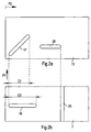
- the supply of the fuel delivered by the prefeed pump 1 to the distributor element 11 takes place through a channel 14, which runs centrally in the drive shaft 7 and into a radially to the drive shaft 7 extending bore 15 opens in an axially extending groove 16 in the outer surface of the drive shaft 7 merges as shown in FIG. 2b Representation of the lateral surface of the drive shaft 7 can be seen is, the arrow P1 in Figure 2b, the direction of rotation of the drive shaft 7 reproduces.
- the delivered by the pre-feed pump 1 Fuel therefore enters the bore via the channel 14 15 and finally in the groove 16.
- the sleeve 13 accordingly has a slot-shaped throughflow opening 17 on, in the outer surface of the sleeve 13 in at an angle of approximately 45 ° to the longitudinal axis of the sleeve 13 runs, the axial extension D1 of the slot-shaped Flow opening 17 is less than the axial extent D2 of the groove 16 in the lateral surface of the drive shaft 7, such as from the representation of the outer surface of the sleeve 13 or Drive shaft 7 can be seen in Figures 2a and 2b.
- the hollow cylindrical housing 12 has on the inside the wall a circumferential over the entire circumference Ring groove 18, in which at one point a radially extending Bore 19 opens out to an outlet of the distributor element 11 forms and with the inlet valve 9 of the associated pump cylinder 5 is connected.
- An axial region 20 shown in the drawing enables So a speed-synchronous control one at a time Pump cylinder 5, so that for a three-cylinder high-pressure pump 4 corresponding to three such axial areas in a row must be arranged.
- a rotation of the drive shaft 7 thus leads to a certain one Angular range of the drive shaft 7 to an overlap the groove arranged in the lateral surface of the drive shaft 7 16 and the slot-shaped flow opening 17 in the sleeve 13, so that the fuel in this angular range of the drive shaft 7 via the channel 14, the tap hole 15, the axial extending groove 16, the oblique throughflow opening 17 in the circumferential annular groove 18 and from there on radial branch bore 19 to the inlet valve 9 of the high pressure pump 4 can reach, which determines the duration of the suction phase is. Outside this angular range, however, seals the sleeve 13 the axially extending groove 16 in the lateral surface the drive shaft 7, so that no fuel to the intake valve 9 of the high pressure pump 4 arrives.
- the duration of the suction phase is influenced lets by axially displacing the sleeve 13 what by an electromagnetic or other actuator, which is not shown for simplicity.
- the overlap begins the groove 16 with the flow opening 17 at the same angular position on, but the overlap ends with an earlier one Angle, which means the duration of the suction phase of the corresponding Pump cylinder is shortened.
- the time of the Beginning of the overlap regardless of the axial position the sleeve 13 is essentially the same for each suction phase, wherein the beginning of the overlap preferably at the top Dead center of the respective pump cylinder 5, which is the beginning of Suction phase of the pump cylinder 5 corresponds. This will Pressure waves at the beginning of the suction phase due to sudden filling a suction vacuum with fuel avoided.
- the fuel flow delivered by the high pressure pump 4 becomes then fed to a pressure accumulator 21 (Common Rail), from which four injectors are supplied with fuel, whereby the injectors are designed in a conventional manner and for simplification are not shown.
- a pressure accumulator 21 Common Rail
- a pressure control valve can be arranged that when exceeded a predetermined maximum pressure on the outlet side the high pressure pump 4 part of the fuel flow branches and returns to the fuel tank 3 until the fuel pressure back to the specified maximum pressure has dropped.
- the pressure control valve and the return in however, the fuel tank 3 is in the drawing for simplification not shown.
- the distributor element 11 enables in addition to that described above Distribution of the feed pump 1 Fuel on the pump cylinder 5 of the high pressure pump 4th also control of the fuel flow through the purge line 22.
- the pressure build-up can be started when the engine is started accelerate by flushing line 22 during the starting process when the distributor element to maximum Suction length is set, is blocked.
- the Sleeve 13 has an axially directed, slot-shaped flow opening 26 on.
- a radially extending bore 27 from which the fuel diverted via the purge line 22 is guided into the housing of the high pressure pump 4 to flush the high pressure pump 4 with fuel, which is cooling and lubrication of the high pressure pump 4 causes. Subsequently the fuel used for flushing purposes leaves the housing the high pressure pump 4 and is via the return line 23 returned to the fuel tank 3.
- the sleeve 13 then by the electromagnetic actuator in Figure 2a pushed to the right until the flow opening 26 the annular groove 25 overlaps, as shown in Figure 1. In this position reaches part of the delivered by the pre-feed pump 1 Fuel over the channel 14, the bore 24, the annular groove 25, the flow opening 26 and the bore 27 in the flushing line 22 and finally in the housing of the high pressure pump 4.
- the fuel flows through the purge line 13 to High pressure pump 4 regardless of the axial position of the sleeve 13, the duration (suction phase) of the fuel inflow to Input of the high pressure pump 4 controls. Only in the starting phase the axial position of the sleeve 13 is adjusted so that at maximum delivery rate to the input of the high pressure pump 4 Fuel flow through the purge line 13 is interrupted.
- the sleeve 13 is preferably by a not shown Spring element biased to the right in the direction of arrow P2, so that the sleeve 13 in the event of actuator failure is pushed to the right, which releases the purge flow but also shortened the suction phase to a certain minimum value becomes. This ensures that a failure of the actuator does not result in permanent flushing failure or too high a flow and thus too high Pressure leads.
- the sleeve and the annular groove 25 in the drive shaft 7 are preferred designed so that when the flow opening overlaps 17 with the groove 16 and the flow opening 26 with the Ring groove 25 of the drive shaft 7 is only an insignificant throttling of fuel flow occurs and therefore less Fuel pressure is adjustable, which reduces the power loss reduced and a smaller one, for example in the tank 1 arranged, electrically operated feed pump 1 used can be.
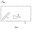
- FIG. 3 finally shows the outer surface of the sleeve 13 in developed state with an alternative version of the Flow opening 26 in the sleeve 13.
- the flow opening 26 is wedge-shaped in the direction of the Annular groove 25 of the drive shaft 7 so that the flush line 22 branched fuel flow with an axial displacement the sleeve 13 is released continuously.
- An axial Displacement of the sleeve 13 in the direction of the arrow thus leads to this arrangement of the flow openings 17 and 26 into one Shortening the duration of the suction phase of the individual pump cylinders 5 with constant suction start and a stepless one Increase in the flushing current in the flushing line 22.
- the wedge-shaped flow opening 26 in connection with the Ring groove 25 partially throttling the purge flow.
- slot-shaped tapers Passage opening 17 at its in the direction of the passage opening 26 lying end wedge-shaped, which at the end of one Suction phase of the fuel flow to the individual pump cylinders 5 is continuously reduced to zero.
- Wedge-shaped flow openings 17, 26 are advantageous abrupt changes in the amount of fuel flow decreased and thus pressure waves in the fuel lines are avoided.
- the course of the flow opening For example, be designed so that the throttling Cross section of the flow opening 26 in the axial direction increases exponentially, resulting in a correspondingly progressive Response of the flushing when the sleeve 13 is displaced leads.
- the groove 25 in the outer surface of the drive shaft can also 7 run in the axial direction when the Flow opening in the sleeve 13 in a ring over the entire Extent of the sleeve 13 extends, being in the annular In this case, the flow opening is distributed over the circumference several axially extending webs are arranged, or the groove the sleeve does not break completely.
- the shaft 7 are axially displaceable. Can too both the sleeve 13 and the shaft are axially displaceable be, the displacement paths then corresponding to one another are coordinated.
- the invention is not limited in its execution the preferred embodiments given above. Rather, a number of variants are conceivable, which of the solution shown, even if fundamentally different Makes use of explanations.
Landscapes
- Engineering & Computer Science (AREA)
- Chemical & Material Sciences (AREA)
- Combustion & Propulsion (AREA)
- Mechanical Engineering (AREA)
- General Engineering & Computer Science (AREA)
- Fuel-Injection Apparatus (AREA)
Abstract
Description
- Figur 1
- eine Einspritzanlage mit einem Drehschieber zur Verteilung des Kraftstoffstroms auf die Pumpzylinder einer Hochdruckpumpe und zur Steuerung des Kraftstoffstroms durch eine Spülleitung,
- Figur 2a
- die Mantelfläche der Hülse des Drehschiebers mit zwei Durchströmöffnungen im abgewickelten Zustand sowie
- Figur 2b
- die Mantelfläche der Welle des Drehschiebers mit zwei Durchströmöffnungen im abgewickelten Zustand,
- Figur 3
- die Mantelfläche der Hülse des Drehschiebers im abgewickelten Zustand mit einer alternativen Anordnung der Durchströmöffnungen.
Claims (15)
- Einspritzanlage für eine Brennkraftmaschine, miteiner Vorförderpumpe (1) zur Förderung von Kraftstoff aus einem Kraftstofftank (3),einer der Vorförderpumpe (1) nachgeordneten Hochdruckpumpe (4) mit mehreren Pumpzylindern (5) zur Erzeugung des erforderlichen Einspritzdrucks für die Kraftstoffeinspritzung in den Brennraum einer Brennkraftmaschine,einem Dosierelement (7,13) im Spülkanal (22) zwischen der Vorförderpumpe (1) und der Hochdruckpumpe (4),wobei das Dosierelement (7,13) als Drehschieber (7,13) ausgebildet ist.
- Einspritzanlage nach Anspruch 1,
dadurch gekennzeichnet, daßein Verteilerelement (11) zwischen der Vorförderpumpe (1) und den Pumpzylindern (5) der Hochdruckpumpe (4) angeordnet ist, das den von der Vorförderpumpe (1) geförderten Kraftstoffstrom (7) auf die einzelnen Pumpzylinder der Hochdruckpumpe (4) verteilt. - Einspritzanlage nach einem der vorherigen Ansprüche,
dadurch gekennzeichnet, daßdas Verteilerelement (11) und das Dosierelement (7,13) in einem Drehschieber (7,11,13) zusammengefaßt sind. - Einspritzanlage für eine Brennkraftmaschine, mitmindestens einer Vorförderpumpe (1) zur Förderung von Kraftstoff aus einem Kraftstofftank (3),mindestens einer der Vorförderpumpe (1) stromabwärts nachgeordneten Hochdruckpumpe (4) mit mehreren Pumpzylindern (5) zur Erzeugung des erforderlichen Einspritzdrucks für die Kraftstoffeinspritzung in einen Brennraum einer Brennkraftmaschine,mindestens einem zwischen Vorförderpumpe (1) und Hochdruckpumpe (4) angeordneten Verteilerelement (11) zur Verteilung des von der Vorförderpumpe (1) geförderten Kraftstoffstroms auf die einzelnen Pumpzylinder (5) der Hochdruckpumpe (4),einer nach der Vorförderpumpe (1) abzweigenden Spülleitung (22), die ausgangsseitig mit der Hochdruckpumpe (4) verbunden ist, um die Hochdruckpumpe (4) mit Kraftstoff zu spülen sowiemindestens einem Ventil zur Steuerung des durch die Spülleitung (22) fließenden Kraftstoffstroms,wobei das mindestens eine Ventil (24-27) zur Steuerung des über die Spülleitung (22) fließenden Kraftstoffstroms in das mindestens eine Verteilerelement (11) integriert ist.
- Einspritzanlage nach Anspruch 4,
dadurch gekennzeichnet, daßdas Ventil (24-27) und das Verteilerelement (11) in einem Drehschieber zusammengefaßt sind. - Einspritzanlage nach einem der Ansprüche 1,2,3 oder 5
dadurch gekennzeichnet, daßder Drehschieber (11,7,13) eine Hülse (13) aufweist, die eine Welle (7) umfaßt unddaß der Kraftstoffstrom durch den Drehschieber (11,7,13) abhängt von der Position der Hülse (13) relativ zur Welle (7). - Einspritzanlage nach Anspruch 6,
dadurch gekennzeichnet, daßdaß die Hülse (13) und die Welle (7) jeweils mindestens eine Ausnehmung (17,26,16,25) aufweisen,daß durch den Drehschieber (7,13) Kraftstoff fließt, wenn sich eine Ausnehmung (17,26) der Hülse (13) mit einer Ausnehmung (16,25) der Welle (7) zumindest teilweise überdeckt,daß der Kraftstoffstrom durch den Drehschieber (11,7,13) abhängt von der axialen Position und/oder von der Winkelstellung der Hülse (13) relativ zur Welle (7) und der Position der Ausnehmungen (17,26,16,25) in der Welle (7) und der Hülse (13). - Einspritzanlage nach Anspruch 6 oder 7,
dadurch gekennzeichnet, daßdie Hülse (13) axial verschiebbar ist und die Welle(7) in der Hülse (13) relativ zu dieser drehbar gelagert ist,
wobei in der Wand der Hülse (13) in einem ersten axialen Bereich (20) mindestens eine erste Durchströmöffnung (17) angeordnet ist, die den Kraftstoffstrom von der Vorförderpumpe (1) zu den einzelnen Pumpzylindern (5) der Hochdruckpumpe (4) jeweils bei vorgegebenen Winkelstellungen der Welle (7) relativ zu der Hülse (13) freigibt,während in einem zweiten axialen Bereich eine zweite Durchströmöffnung (26) angeordnet ist, die den über die Spülleitung (22) abzweigenden Kraftstoffstrom in Abhängigkeit von der axialen Stellung der Hülse (13) relativ zu der Welle (7) steuert. - Einspritzanlage nach Anspruch 8,
dadurch gekennzeichnet, daßdie erste Durchströmöffnung (17) mindestens teilweise schräg zur Längsachse der Welle (7) verläuft, so daß eine axiale Verschiebung zu einer Änderung der Durchlaßdauer und damit zu einer Änderung der Dauer der Saugphase der Pumpzylinder (5) der Hochdruckpumpe (4) führt. - Einspritzanlage nach Anspruch 8 oder 9,
dadurch gekennzeichnet,daß sich der Querschnitt der zweiten Durchströmöffnung (26) mindestens teilweise in axialer Richtung ändert, um den über die Spülleitung (22) abzweigenden Kraftstoffstrom in Abhängigkeit von der axialen Stellung stufenweise oder stufenlos steuern zu können. - Einspritzanlage nach einem der Ansprüche 7 bis 10,
dadurch gekennzeichnet,daß die Welle (7) einen axial verlaufenden Kanal (14) zur Kraftstoffzuführung aufweist, wobei in der Mantelfläche der Welle (7) jeweils Nuten (16, 25) angeordnet sind, die mit dem Kanal (14) verbunden sind. - Einspritzanlage nach einem der Ansprüche 7 bis 11,
dadurch gekennzeichnet,daß die Welle (7) und die Hülse (13) in einem hohlzylindrischen Gehäuse (12) angeordnet sind, wobei in der Mantelfläche des Gehäuses (12) in dem ersten axialen Bereich (20) eine umlaufende Nut (18) angeordnet ist. - Einspritzanlage nach einem der Ansprüche 6 bis 12,
dadurch gekennzeichnet, daß die Welle(7) axial verschiebbar ist. - Einspritzanlage nach einem der Ansprüche 1 bis 13,
dadurch gekennzeichnet, daß in der Startstellung die Dosierelement bzw. das Ventil sperrt und das Verteilerelement (11) so aufgesteuert ist, daß die Zuleitung zu den Pumpenzylindern offen ist. - Einspritzanlage nach einem der Ansprüche 6 bis 14,
dadurch gekennzeichnet, daß die Welle (7) als Antriebswelle ausgebildet ist.
Applications Claiming Priority (2)
| Application Number | Priority Date | Filing Date | Title |
|---|---|---|---|
| DE1999151999 DE19951999B4 (de) | 1999-10-28 | 1999-10-28 | Einspritzanlage für eine Brennkraftmaschine |
| DE19951999 | 1999-10-28 |
Publications (3)
| Publication Number | Publication Date |
|---|---|
| EP1096135A2 true EP1096135A2 (de) | 2001-05-02 |
| EP1096135A3 EP1096135A3 (de) | 2004-03-31 |
| EP1096135B1 EP1096135B1 (de) | 2008-10-15 |
Family
ID=7927205
Family Applications (1)
| Application Number | Title | Priority Date | Filing Date |
|---|---|---|---|
| EP20000123143 Expired - Lifetime EP1096135B1 (de) | 1999-10-28 | 2000-10-25 | Einspritzanlage für eine Brennkraftmaschine |
Country Status (2)
| Country | Link |
|---|---|
| EP (1) | EP1096135B1 (de) |
| DE (2) | DE19951999B4 (de) |
Families Citing this family (1)
| Publication number | Priority date | Publication date | Assignee | Title |
|---|---|---|---|---|
| DE10216205B4 (de) * | 2002-04-12 | 2007-04-05 | Robert Bosch Gmbh | Kraftstoffhochdruckpumpe mit Fördermengenregelung |
Citations (1)
| Publication number | Priority date | Publication date | Assignee | Title |
|---|---|---|---|---|
| WO1995025887A1 (de) | 1994-03-23 | 1995-09-28 | Siemens Aktiengesellschaft | Anordnung zur einspritzung von kraftstoff in die zylinder einer brennkraftmaschine |
Family Cites Families (4)
| Publication number | Priority date | Publication date | Assignee | Title |
|---|---|---|---|---|
| US4951626A (en) * | 1988-02-10 | 1990-08-28 | Robert Bosch Gmbh | Electrically controlled fuel injection pump |
| DE3927742A1 (de) * | 1989-08-23 | 1991-02-28 | Bosch Gmbh Robert | Kraftstoffeinspritzpumpe fuer brennkraftmaschinen |
| DE19742180C2 (de) * | 1997-09-24 | 1999-07-08 | Siemens Ag | Einspritzsystem für eine Brennkraftmaschine und Verfahren zum Regeln eines Einspritzsystems |
| DE19854509C2 (de) * | 1998-11-25 | 2000-11-23 | Siemens Ag | Vorrichtung zum Erzeugen eines variablen Volumenstromes bei einer Kraftstoffzuführung |
-
1999
- 1999-10-28 DE DE1999151999 patent/DE19951999B4/de not_active Expired - Fee Related
-
2000
- 2000-10-25 DE DE50015402T patent/DE50015402D1/de not_active Expired - Lifetime
- 2000-10-25 EP EP20000123143 patent/EP1096135B1/de not_active Expired - Lifetime
Patent Citations (1)
| Publication number | Priority date | Publication date | Assignee | Title |
|---|---|---|---|---|
| WO1995025887A1 (de) | 1994-03-23 | 1995-09-28 | Siemens Aktiengesellschaft | Anordnung zur einspritzung von kraftstoff in die zylinder einer brennkraftmaschine |
Also Published As
| Publication number | Publication date |
|---|---|
| DE19951999B4 (de) | 2004-11-18 |
| DE19951999A1 (de) | 2001-05-03 |
| EP1096135A3 (de) | 2004-03-31 |
| EP1096135B1 (de) | 2008-10-15 |
| DE50015402D1 (de) | 2008-11-27 |
Similar Documents
| Publication | Publication Date | Title |
|---|---|---|
| DE69409741T2 (de) | Brennstoffsystem | |
| DE2045556C3 (de) | Vorrichtung zur Kraftstoffeinspritzung in die Zylinder einer mit Druckzündung arbeitenden Brennkraftmaschine | |
| EP2449245B1 (de) | Kraftstoffsystem für eine brennkraftmaschine | |
| WO2016075041A2 (de) | Niederdruckregelsystem einer kraftstofffördereinrichtung eines kraftstoffeinspritzsystems sowie ein absteuerventil dazu | |
| DE2818450A1 (de) | Einspritzvorrichtung fuer fluessigen kraftstoff | |
| DE3545052A1 (de) | Brennstoff-einspritzpumpe fuer eine wenigstens vierzylindrige brennkraftmaschine | |
| DE1919969C2 (de) | Kraftstoffeinspritzpumpe für Brennkraftmaschinen | |
| DE2447720A1 (de) | Kraftstoffeinspritzanlage | |
| DE60116985T2 (de) | Dosiervorrichtung mit optimierter Einstellung | |
| EP0960275A1 (de) | Hochdruckpumpe zur kraftstoffversorgung bei kraftstoffeinspritzsystemen von brennkraftmaschinen | |
| DE2622106A1 (de) | Kraftstoff-steuerventil | |
| DE10244551A1 (de) | Kraftstoffeinspritzeinrichtung für eine Brennkraftmaschine | |
| EP0419591A1 (de) | Steuereinrichtung zum stillsetzen einer brennkraftmaschine. | |
| EP1185785B1 (de) | Einspritzsystem | |
| DE3524980C2 (de) | Kraftstoffeinspritzpumpe für eine Brennkraftmaschine | |
| DE2930221A1 (de) | Kraftstoffeinspritzsystem und -pumpe, dafuer vorgesehenes druckventil und kraftstoffeinspritzverfahren | |
| EP0882180A1 (de) | Kraftstoffeinspritzsystem | |
| EP1096135B1 (de) | Einspritzanlage für eine Brennkraftmaschine | |
| DE2937222A1 (de) | Kraftstoff-einspritzpumpvorrichtung | |
| DE69604443T2 (de) | Kraftstoffzufuhreinrichtung | |
| DE19933567C1 (de) | Einspritzsystem für eine Brennkraftmaschine | |
| DE3545050A1 (de) | Brennstoff-einspritzpumpe fuer eine wenigstens vierzyindrige brennkraftmaschine | |
| EP1049869B1 (de) | Vorrichtung zum erzeugen eines variablen volumenstromes bei einer kraftstoffzuführung | |
| DE2716854A1 (de) | Kraftstoff-foerderanlage | |
| DE19619522A1 (de) | Einspritzeinrichtung |
Legal Events
| Date | Code | Title | Description |
|---|---|---|---|
| PUAI | Public reference made under article 153(3) epc to a published international application that has entered the european phase |
Free format text: ORIGINAL CODE: 0009012 |
|
| AK | Designated contracting states |
Kind code of ref document: A2 Designated state(s): AT BE CH CY DE DK ES FI FR GB GR IE IT LI LU MC NL PT SE |
|
| AX | Request for extension of the european patent |
Free format text: AL;LT;LV;MK;RO;SI |
|
| RIC1 | Information provided on ipc code assigned before grant |
Ipc: 7F 02M 41/06 A Ipc: 7F 02M 59/34 B Ipc: 7F 02M 63/02 B Ipc: 7F 02M 59/36 B Ipc: 7F 02M 37/18 B |
|
| PUAL | Search report despatched |
Free format text: ORIGINAL CODE: 0009013 |
|
| AK | Designated contracting states |
Kind code of ref document: A3 Designated state(s): AT BE CH CY DE DK ES FI FR GB GR IE IT LI LU MC NL PT SE |
|
| AX | Request for extension of the european patent |
Extension state: AL LT LV MK RO SI |
|
| 17P | Request for examination filed |
Effective date: 20040419 |
|
| AKX | Designation fees paid |
Designated state(s): DE FR GB IT |
|
| 17Q | First examination report despatched |
Effective date: 20060213 |
|
| GRAP | Despatch of communication of intention to grant a patent |
Free format text: ORIGINAL CODE: EPIDOSNIGR1 |
|
| RAP1 | Party data changed (applicant data changed or rights of an application transferred) |
Owner name: CONTINENTAL AUTOMOTIVE GMBH |
|
| GRAS | Grant fee paid |
Free format text: ORIGINAL CODE: EPIDOSNIGR3 |
|
| GRAA | (expected) grant |
Free format text: ORIGINAL CODE: 0009210 |
|
| AK | Designated contracting states |
Kind code of ref document: B1 Designated state(s): DE FR GB IT |
|
| REG | Reference to a national code |
Ref country code: GB Ref legal event code: FG4D Free format text: NOT ENGLISH |
|
| REF | Corresponds to: |
Ref document number: 50015402 Country of ref document: DE Date of ref document: 20081127 Kind code of ref document: P |
|
| PLBE | No opposition filed within time limit |
Free format text: ORIGINAL CODE: 0009261 |
|
| STAA | Information on the status of an ep patent application or granted ep patent |
Free format text: STATUS: NO OPPOSITION FILED WITHIN TIME LIMIT |
|
| PG25 | Lapsed in a contracting state [announced via postgrant information from national office to epo] |
Ref country code: IT Free format text: LAPSE BECAUSE OF FAILURE TO SUBMIT A TRANSLATION OF THE DESCRIPTION OR TO PAY THE FEE WITHIN THE PRESCRIBED TIME-LIMIT Effective date: 20081015 |
|
| 26N | No opposition filed |
Effective date: 20090716 |
|
| GBPC | Gb: european patent ceased through non-payment of renewal fee |
Effective date: 20090115 |
|
| PG25 | Lapsed in a contracting state [announced via postgrant information from national office to epo] |
Ref country code: GB Free format text: LAPSE BECAUSE OF NON-PAYMENT OF DUE FEES Effective date: 20090115 |
|
| PGFP | Annual fee paid to national office [announced via postgrant information from national office to epo] |
Ref country code: DE Payment date: 20141031 Year of fee payment: 15 |
|
| REG | Reference to a national code |
Ref country code: FR Ref legal event code: PLFP Year of fee payment: 16 |
|
| PGFP | Annual fee paid to national office [announced via postgrant information from national office to epo] |
Ref country code: FR Payment date: 20151023 Year of fee payment: 16 |
|
| REG | Reference to a national code |
Ref country code: DE Ref legal event code: R119 Ref document number: 50015402 Country of ref document: DE |
|
| PG25 | Lapsed in a contracting state [announced via postgrant information from national office to epo] |
Ref country code: DE Free format text: LAPSE BECAUSE OF NON-PAYMENT OF DUE FEES Effective date: 20160503 |
|
| REG | Reference to a national code |
Ref country code: FR Ref legal event code: ST Effective date: 20170630 |
|
| PG25 | Lapsed in a contracting state [announced via postgrant information from national office to epo] |
Ref country code: FR Free format text: LAPSE BECAUSE OF NON-PAYMENT OF DUE FEES Effective date: 20161102 |