EP1095904A2 - Reaktoranlage zur katalytischen Brennstoffumsetzung mit Wasser und Sauerstoff - Google Patents
Reaktoranlage zur katalytischen Brennstoffumsetzung mit Wasser und Sauerstoff Download PDFInfo
- Publication number
- EP1095904A2 EP1095904A2 EP00119233A EP00119233A EP1095904A2 EP 1095904 A2 EP1095904 A2 EP 1095904A2 EP 00119233 A EP00119233 A EP 00119233A EP 00119233 A EP00119233 A EP 00119233A EP 1095904 A2 EP1095904 A2 EP 1095904A2
- Authority
- EP
- European Patent Office
- Prior art keywords
- fuel
- water
- educt
- starting material
- oxygen
- Prior art date
- Legal status (The legal status is an assumption and is not a legal conclusion. Google has not performed a legal analysis and makes no representation as to the accuracy of the status listed.)
- Granted
Links
Images



Classifications
-
- B—PERFORMING OPERATIONS; TRANSPORTING
- B01—PHYSICAL OR CHEMICAL PROCESSES OR APPARATUS IN GENERAL
- B01J—CHEMICAL OR PHYSICAL PROCESSES, e.g. CATALYSIS OR COLLOID CHEMISTRY; THEIR RELEVANT APPARATUS
- B01J8/00—Chemical or physical processes in general, conducted in the presence of fluids and solid particles; Apparatus for such processes
- B01J8/008—Details of the reactor or of the particulate material; Processes to increase or to retard the rate of reaction
- B01J8/0085—Details of the reactor or of the particulate material; Processes to increase or to retard the rate of reaction promoting uninterrupted fluid flow, e.g. by filtering out particles in front of the catalyst layer
-
- B—PERFORMING OPERATIONS; TRANSPORTING
- B01—PHYSICAL OR CHEMICAL PROCESSES OR APPARATUS IN GENERAL
- B01J—CHEMICAL OR PHYSICAL PROCESSES, e.g. CATALYSIS OR COLLOID CHEMISTRY; THEIR RELEVANT APPARATUS
- B01J19/00—Chemical, physical or physico-chemical processes in general; Their relevant apparatus
- B01J19/26—Nozzle-type reactors, i.e. the distribution of the initial reactants within the reactor is effected by their introduction or injection through nozzles
-
- B—PERFORMING OPERATIONS; TRANSPORTING
- B01—PHYSICAL OR CHEMICAL PROCESSES OR APPARATUS IN GENERAL
- B01J—CHEMICAL OR PHYSICAL PROCESSES, e.g. CATALYSIS OR COLLOID CHEMISTRY; THEIR RELEVANT APPARATUS
- B01J8/00—Chemical or physical processes in general, conducted in the presence of fluids and solid particles; Apparatus for such processes
- B01J8/02—Chemical or physical processes in general, conducted in the presence of fluids and solid particles; Apparatus for such processes with stationary particles, e.g. in fixed beds
- B01J8/0278—Feeding reactive fluids
-
- C—CHEMISTRY; METALLURGY
- C01—INORGANIC CHEMISTRY
- C01B—NON-METALLIC ELEMENTS; COMPOUNDS THEREOF; METALLOIDS OR COMPOUNDS THEREOF NOT COVERED BY SUBCLASS C01C
- C01B3/00—Hydrogen; Gaseous mixtures containing hydrogen; Separation of hydrogen from mixtures containing it; Purification of hydrogen; Reversible storage of hydrogen
- C01B3/02—Production of hydrogen; Production of gaseous mixtures containing hydrogen
- C01B3/32—Production of hydrogen; Production of gaseous mixtures containing hydrogen by reaction of gaseous or liquid organic compounds with gasifying agents, e.g. water, carbon dioxide or air
- C01B3/34—Production of hydrogen; Production of gaseous mixtures containing hydrogen by reaction of gaseous or liquid organic compounds with gasifying agents, e.g. water, carbon dioxide or air by reaction of hydrocarbons with gasifying agents
- C01B3/38—Production of hydrogen; Production of gaseous mixtures containing hydrogen by reaction of gaseous or liquid organic compounds with gasifying agents, e.g. water, carbon dioxide or air by reaction of hydrocarbons with gasifying agents using catalysts
- C01B3/382—Processes with two or more reaction steps, of which at least one is catalytic, e.g. steam reforming and partial oxidation
-
- B—PERFORMING OPERATIONS; TRANSPORTING
- B01—PHYSICAL OR CHEMICAL PROCESSES OR APPARATUS IN GENERAL
- B01J—CHEMICAL OR PHYSICAL PROCESSES, e.g. CATALYSIS OR COLLOID CHEMISTRY; THEIR RELEVANT APPARATUS
- B01J2208/00—Processes carried out in the presence of solid particles; Reactors therefor
- B01J2208/00008—Controlling the process
- B01J2208/00017—Controlling the temperature
- B01J2208/00106—Controlling the temperature by indirect heat exchange
- B01J2208/00309—Controlling the temperature by indirect heat exchange with two or more reactions in heat exchange with each other, such as an endothermic reaction in heat exchange with an exothermic reaction
-
- B—PERFORMING OPERATIONS; TRANSPORTING
- B01—PHYSICAL OR CHEMICAL PROCESSES OR APPARATUS IN GENERAL
- B01J—CHEMICAL OR PHYSICAL PROCESSES, e.g. CATALYSIS OR COLLOID CHEMISTRY; THEIR RELEVANT APPARATUS
- B01J2208/00—Processes carried out in the presence of solid particles; Reactors therefor
- B01J2208/00008—Controlling the process
- B01J2208/00539—Pressure
-
- C—CHEMISTRY; METALLURGY
- C01—INORGANIC CHEMISTRY
- C01B—NON-METALLIC ELEMENTS; COMPOUNDS THEREOF; METALLOIDS OR COMPOUNDS THEREOF NOT COVERED BY SUBCLASS C01C
- C01B2203/00—Integrated processes for the production of hydrogen or synthesis gas
- C01B2203/14—Details of the flowsheet
- C01B2203/142—At least two reforming, decomposition or partial oxidation steps in series
-
- C—CHEMISTRY; METALLURGY
- C01—INORGANIC CHEMISTRY
- C01B—NON-METALLIC ELEMENTS; COMPOUNDS THEREOF; METALLOIDS OR COMPOUNDS THEREOF NOT COVERED BY SUBCLASS C01C
- C01B2203/00—Integrated processes for the production of hydrogen or synthesis gas
- C01B2203/80—Aspect of integrated processes for the production of hydrogen or synthesis gas not covered by groups C01B2203/02 - C01B2203/1695
- C01B2203/82—Several process steps of C01B2203/02 - C01B2203/08 integrated into a single apparatus
-
- Y—GENERAL TAGGING OF NEW TECHNOLOGICAL DEVELOPMENTS; GENERAL TAGGING OF CROSS-SECTIONAL TECHNOLOGIES SPANNING OVER SEVERAL SECTIONS OF THE IPC; TECHNICAL SUBJECTS COVERED BY FORMER USPC CROSS-REFERENCE ART COLLECTIONS [XRACs] AND DIGESTS
- Y02—TECHNOLOGIES OR APPLICATIONS FOR MITIGATION OR ADAPTATION AGAINST CLIMATE CHANGE
- Y02P—CLIMATE CHANGE MITIGATION TECHNOLOGIES IN THE PRODUCTION OR PROCESSING OF GOODS
- Y02P20/00—Technologies relating to chemical industry
- Y02P20/10—Process efficiency
- Y02P20/129—Energy recovery, e.g. by cogeneration, H2recovery or pressure recovery turbines
Definitions
- the invention relates to a reactor system for catalytic Implementation of a hydrocarbon or hydrocarbon derivative fuel with water and oxygen, the Reactor plant a catalyst-occupied reaction space and Educt supply means for supplying an educt mixture with the Fuel as a first educt, water as a second Educt and an oxygen-containing gas as a third educt has in the reaction space.
- the fuel, the water and an oxygen-containing gas, e.g. Air, through Corresponding starting material feed means are fed to a reaction space, which is coated with a suitable catalyst material.
- Converted fuel with water and oxygen Converted fuel with water and oxygen.
- the implementation reaction generally includes an endothermic one Reforming reaction of the fuel with the water and on the other hand an exothermic oxidation reaction of the fuel with the oxygen.
- the reaction can be set autothermally, i.e. provides the exothermic reaction of the fuel with the oxygen especially for the endothermic reforming of the fuel heat required with water, so that neither cooling, heating of the reaction space is still necessary.
- Aim this Kind of implementation reactions is the extraction of a hydrogen-rich one Gas from the fuel, e.g. Gasoline or methanol, around the hydrogen generated thereby e.g. for feeding Fuel cells of a fuel cell vehicle or one to use stationary fuel cell system.
- catalyst for the reaction space Possibilities. So the catalyst material as Pellet fill or as a wall coating. Another One possibility is to attach the catalyst material a high surface area catalyst support.
- various structures are considered as catalyst supports, such as monolith structures made of metal or ceramic, ceramic foams, Wire mesh panels or cross-channel structures that function as static Mixers work.
- For an effective implementation of the fuel is a homogeneous distribution of the three starting materials to strive for in the catalyst-occupied reaction space.
- In the reaction room itself is often a homogeneous mixture of starting materials hardly accessible anymore, especially with monolithic catalyst support structures, where in the catalyst carrier area no product gas exchange is possible.
- the educts before Pre-evaporate entry into the reaction space especially that Water and the usually also liquid fuel, premix and as a corresponding gas / vapor mixture in the reaction chamber initiate.
- US Pat. No. 4,024,912 describes a multi-stage reactor system described in which in a first stage a hydrocarbon material in the form of an oil with the help of superheated Water vapor is atomized and fed into a combustion chamber Oxygen is burned non-catalytically, whereby the resulting carbon monoxide and hydrogen containing Product gas in a downstream, catalyzed Reformer chamber for performing a water gas reaction under Supply of water or steam is initiated. In the reformist chamber generated heat is used to heat the water for atomization of the hydrocarbon material.
- DE 29 02 845 A1 discloses a reactor system described for the production of gases from heavy oils, why the heavy oil is atomized and together with water vapor through a Passed high temperature zone in the form of a heat cracking tube is then through a catalyst layer to be passed through from alkaline earth metal oxides. Both that Heavy oil as well as water vapor are removed before atomization preferably preheated, the preheated water vapor together can be supplied with a gas mixture that contains oxygen, Contains hydrogen and carbon dioxide.
- the burner unit for mixing individual feed streams to form a Multi-phase mixture and for the implementation of the same in a partial oxidation gas generator described.
- the burner unit is designed as a single or multiple ring burner unit and specifically serves to pumpable slurries of carbonaceous Solid fuels in a carrier liquid, such as Water and / or liquid or gaseous hydrocarbons to implement by partial oxidation. To do this, the burner unit e.g.
- the burner unit can have at least one premixing zone for mixing two reactant streams may be provided.
- the invention is a technical problem of providing a reactor plant of the type mentioned, which is ensured with relatively little effort that the three starting materials in sufficiently well mixed form in the catalyst-coated Get reaction space.
- This reactor plant includes as part of the feed material an educt mixture preparation room with its outlet side to the entry side of the catalyst-occupied reaction space adjacent.
- the educt feed means further include Fuel injection means with which the fuel in liquid Form in the educt mixture preparation room with formation of droplets is injected, and gas supply means designed so are that they are swirling the oxygenated gas of fuel droplets in the Feed educt mixture preparation room, and water supply means, through which the water in the educt mixture preparation room reached.
- the water supply means operate differently depending on this, whether the reactor plant is in a cold start phase or in the warm operating condition Condition. In the former case, they dose the water in atomized form while in the latter If the water is dispensed in an evaporated form.
- the one to evaporate of the liquid water required for heat is supplied by system heat feedback. A previous one Evaporation of the water is at least during this Cold start phases are not required.
- the educt feed means include several feed nozzles on the inlet side of the Educt gas processing room are arranged distributed and of which each one or more of the three reactants in the reactant gas processing room added.
- the reactant feed means thus implemented according to claim 1 or 2 ensure that the three are thoroughly mixed Educts, i.e. a sufficiently homogeneous educt mixture, already in the educt mixture preparation room, which is connected upstream of the reaction room is, so that the educt mixture with good, sufficient Homogeneity of the mixing of the three starting materials in the reaction space reached.
- the fuel used is in good enough with that Water and the mixed gas containing oxygen in the Bring the reaction space and e.g. autothermal in a hydrogen-rich Implement gas.
- the reactor plant according to the invention can be easily interpreted so that they also special conditions for mobile use, e.g. in Fuel cell vehicles, such as satisfying dynamics and temperature resistance, sufficient load spreading capacity, complete evaporation of the fuel and one of the Installation position independent operability, the latter especially when installing in motor vehicles is important.
- the gas supply means specifically swirl flow generating means.
- the swirl flow of the oxygen-containing feed which is fed in by them Gases promotes a good swirling of the injected Droplets of fuel in the educt mixture preparation room.
- the gas supply means specially preheating means to the oxygen-containing Gas through compression and / or system heat feedback before or at the latest in the educt mixture preparation room and thus to warm up before entering the reaction space.
- System heat feedback is the use of heat Understanding the heating of the oxygen-containing gas the system itself is won, e.g. while cooling off the product gas emerging from the reaction space or one of the reaction space downstream system component, such as a downstream Gas cleaning stage for exothermic conversion and thus eliminating carbon monoxide contained in the product gas.
- the Water supply means designed so that they atomized or evaporate evaporated water into the oxygen-containing gas stream, before putting it together with this into the educt mixture preparation room is fed so that a common supply channel to the Introducing the water and the oxygen-containing gas stream into the educt mixture preparation room is sufficient.
- the Educt mixture preparation room a main room and an upstream Premixing chamber.
- the three starting materials are in the premixing chamber introduced and premixed there. From the premixing chamber then they get into the main room, e.g. with swirl generation.
- a very intensive starting material mixing can be achieved, e.g. due to the pre-mixing chamber extended mixture flow path and / or by an increase the mixture flow rate as determined by appropriate Design of the outflow geometry of the premixing chamber, in particular a cross-sectional tapering of the same can be achieved is.
- the starting material feed means a single one, preferably at a central one Location of the entry side of the educt mixture preparation room arranged multi-component nozzle, over which all three educts in the educt mixture preparation room can be fed.
- the multi-component nozzle as a two-component or three-component nozzle the three educts of this nozzle are fed separately, or it are two starting materials in premixed form via a first inlet channel and the third educt via a second inlet channel fed to the multi-component nozzle.
- Fig. 1 shows schematically a part of a reactor plant of interest here for the autothermal conversion of a hydrocarbon fuel (given in the usual general notation CnHm), for example gasoline, with water and oxygen for the purpose of obtaining a hydrogen-rich product gas which generally also contains carbon monoxide and, if appropriate, other by-products contains.
- the reaction takes place in a preferably autothermal reaction zone defined by a reaction chamber 1 and usually comprises, on the one hand, an endothermic steam reforming and, on the other hand, an exothermic partial oxidation of the fuel.
- the reaction can be set autothermally by appropriate process control, in particular with regard to temperature and pressure in the reaction space 1 and the amount of the respective educt, especially the quantitative ratio of water and oxygen, which has the advantage that the reaction space 1 is neither cooled nor heated got to.
- a catalyst material suitable for catalyzing the reaction is introduced into the reaction space 1 in a conventional manner, for example in the form of a catalyst support provided with the catalyst material.
- Possible catalyst support structures are monolithic structures made of metal or ceramic, ceramic foams, wire mesh disks, cross-channel structures acting as static mixers and the like.
- starting material supply means which contain a starting material treatment zone directly adjacent to the inlet side 1a of the reaction space 1, which zone is provided by a corresponding one Educt mixture preparation room 2 is realized.
- suitable educt metering means are arranged which contain the fuel CnHm, the water and the oxygen, the latter for example in the form of air, with good mixing in the Introduce mixture preparation chamber 2, the geometry of mixture preparation chamber 2 also being able to contribute to the mixing of the three starting materials.
- the three educts are metered into the educt mixture preparation room 2 through a single, central multi-component nozzle 3.
- the feed nozzle 3 can be electromagnetic, for example actuatable injector include, as is typically is used in internal combustion engines.
- This injector part the feed nozzle 3 can, as also from conventional internal combustion engine injection systems known, either through a low pressure system with typical pressures up to about 5bar or above a high pressure system with typical pressures between about 20bar and be supplied about 120bar.
- the air is metered in such a way that it is injected of the fuel droplets formed maximally swirled to ensure the best possible mixing of the combustion air to achieve with the fuel.
- this can be achieved by an air flow guide, the one generates the greatest possible swirl.
- air preheating favorable resulting from compression of the intake air and / or can be achieved by system heat recovery.
- the air is heated to approx. 200 ° C.
- the air compression primarily serves the air through the supply nozzle 3 to be introduced in the form of a jet into the mixture preparation room 2 and overall, the educt mixture prepared there with sufficient Feed excess pressure into reaction chamber 1.
- the system heat return mentioned consists of the reaction chamber 1 escaping product gas or a downstream of the reaction chamber 1 System component, such as a gas cleaning stage, excess Extract heat and this to the educt feed and use it there, e.g. for the air preheating mentioned.
- the water is metered into the mixture preparation room 2 preferably depending on whether the reactor plant is in a cold start phase or in a warm operating condition. During the cold start phase, water is metered in by that finely atomized liquid water is injected into the air stream becomes.
- Water atomization can be carried out using a conventional for this purpose common nozzle, such as one Nebulizer or an injector that is the supply nozzle 3 is upstream and the atomized water before the air flow Admission into the feed nozzle 3 admixed. This admixture can also take place in a two-component nozzle, which on the one hand is the Air flow and on the other hand the liquid water is supplied.
- Another alternative is the atomization of the liquid water only through the supply nozzle 3 itself, for which purpose is then appropriately designed.
- the liquid water can also needs the liquid fuel before entering the feed nozzle 3 added and atomized together with this.
- the feed nozzle 3 includes a conventional injection valve 3a, via which the fuel at an outlet nozzle 3b in the educt mixture preparation room 2 with a wide, conical beam injected and thereby atomized.
- a premixed air / water flow 8 in the mixture preparation room 2 fed Via a lateral inflow channel 7 of the feed nozzle 3, a premixed air / water flow 8 in the mixture preparation room 2 fed.
- the water is in front of the inlet channel 7a of the feed nozzle 3 into the supplied air flow, as explained above, added in the form of a vapor or atomized.
- the Inflow channel 7 goes into swirl flow channels 9 on the outlet side over that in a subsequent part of the inside of the Mixture formation space 2 defining housing part 6 is provided are.
- the eccentric swirl flow channels 9 cause a flow guide offset from the center for the supplied the admixed vaporous or atomized water containing Air flow with high swirl effect. This causes one strong turbulence injected with the central injection cone Droplets of fuel due to the swirl air flow in the educt mixture preparation room 2. Overall, this becomes a very homogeneous and finely distributed mixing of the three starting materials in the mixture preparation room 2 scored.
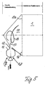
- Fig. 5 shows another embodiment with respect to Eduktzu slaughter, for the rest for functionally identical elements the same reference numerals as in the embodiment of FIG 1 to 4 are used.
- Educt mixture preparation room from a main room 10 and one this upstream premixing chamber 11.
- Such premixing chamber arrangements are, for example, motor vehicle diesel engines known.
- the educt mixture is primarily processed in the Premixing chamber 11, from which the prepared educt mixture passes a connecting channel 12 is fed into the main room 10.
- the main room 10 in turn closes with its outlet side 10a directly to the inlet side 1a of the reaction space 1 and is otherwise designed so that he strong turbulence of the the premixing chamber 11 coming laterally entering, premixed Educt stream 13 causes, as by a swirl line 14th symbolizes. It also contributes to a particularly intense Mixing of the three starting materials through the upstream premixing chamber 11 extended flow path for the educt mixture and an increased flow rate of the educt mixture, with a special outflow geometry of the premixing chamber 11 is effected and in particular a corresponding cross-sectional taper includes.
- FIG. 6 shows the educt mixture preparation room 2, the outlet side again adjacent to the entry side of the reaction space 1, an entrance surface 2c over which a plurality of adjacent feed nozzles 15 evenly distributed as two-dimensional nozzle array is arranged.
- the feed nozzles 15 are designed as single-substance nozzles, each of which is supplied to it Inject the educt into the mixture preparation room 2.
- first third 15a of the feed nozzles 15 to be fed Water a second third 15b the air to be fed and a third third 15c of the fuel to be injected.
- the distribution of the feed nozzles 15 over the three starting materials is chosen as evenly as possible, so that along any In the direction of the entry surface 2c, the supply nozzles for water, air and fuel follow each other cyclically or a nozzle that that carries an educt, is only surrounded by nozzles, which the two lead other starting materials.
- the Feed nozzles 15 are also formed by two-substance or three-substance nozzles be, of course, the use of both Single-substance nozzles and two-substance nozzles can be provided can.
- three-substance nozzles are used, all of them fed three educts and together from the concerned Three-substance nozzle in a well-mixed form in the mixture preparation room 2 injected.
- two-component nozzles two of the three starting materials for joint feeding in the mixture preparation room 2 fed, while the third Educt alone or together with further portions of the first and / or the second starting material is injected via another of the feed nozzles 15 becomes.
- controllable feed nozzles are preferably used, e.g. can be controlled proportionally or of which when in use flat metering via several feed nozzles Part of the nozzles can be turned off to a desired one Allow load spreading.
- metering control of the feed nozzles can be continuous or depending on the application discontinuous metering may be provided.
- the continuous Dosing can e.g. a pressure control or a proportional control associated, controllable metering openings.
- a discontinuous metering can be done at the time Timing of controllable metering openings with variable Realize clock frequency and if necessary with additional pressure control.
- the present fuel is not only Gasoline, but also other hydrocarbons or hydrocarbon derivatives are suitable for reforming and oxidation a hydrogen-rich gas can be converted, e.g. Methanol.
- the reactor plant according to the invention can be very well to provide hydrogen for a fuel cell Use fuel cell vehicle because they are the specific Conditions for such a mobile application well met, such as sufficient load spread and dynamics, temperature resistance and position-independent functionality. The latter makes it easier installation in the motor vehicle with its mostly cramped installation space.
- the reactor plant according to the invention not only for mobile, but also for stationary systems suitable wherever from a hydrocarbon or Hydrocarbon derivative obtained a hydrogen-rich gas shall be. Depending on your needs, process control is not required must be autothermal, but can also be endothermic overall or be set exothermic.
Landscapes
- Chemical & Material Sciences (AREA)
- Chemical Kinetics & Catalysis (AREA)
- Organic Chemistry (AREA)
- Health & Medical Sciences (AREA)
- General Health & Medical Sciences (AREA)
- Engineering & Computer Science (AREA)
- Combustion & Propulsion (AREA)
- Inorganic Chemistry (AREA)
- Physics & Mathematics (AREA)
- Fluid Mechanics (AREA)
- Hydrogen, Water And Hydrids (AREA)
Abstract
Description
- Fig. 1
- eine schematische Prinzipskizze einer Reaktoranlage mit zentraler Eduktzuführung in einen Eduktgemischaufbereitungsraum,
- Fig. 2
- eine Längsschnittansicht einer gemäß der Prinzipskizze von Fig. 1 realisierten Reaktoranlage,
- Fig. 3
- eine Draufsicht auf den Eduktgemischaufbereitungsraum von Fig. 2 mit mittenversetzter Gasströmungsführung zur Drallerzeugung,
- Fig .4
- eine Schnittansicht längs der Linie IV-IV von Fig. 3,
- Fig .5
- eine Prinzipskizze entsprechend Fig. 1, jedoch für eine Reaktoranlage mit Vormischkammer und
- Fig. 6
- eine Prinzipskizze einer Reaktoranlage mit flächiger Düsenanordnung an der Eintrittseite eines Eduktgemischaufbereitungsraums.
Claims (7)
- Reaktoranlage zur katalytischen Umsetzung eines Kohlenwasserstoff- oder Kohlenwasserstoffderivat-Brennstoffs mit Wasser und Sauerstoff, miteinem katalysatorbelegten Reaktionsraum (1) undEduktzufuhrmitteln zur Zuführung eines Eduktgemischs mit dem Brennstoff als einem ersten Edukt, dem Wasser als einem zweiten Edukt und einem sauerstoffhaltigen Gas als einem dritten Edukt in den Reaktionsraum, wobei die Eduktzufuhrmitteli) einen austrittsseitig an die Eintrittsseite (1a) des Reaktionsraums (1) angrenzenden Eduktgemischaufbereitungsraum (2),ii) Brennstoffeinspritzmittel, die den Brennstoff in flüssiger Form tröpfchenbildend in den Eduktgemischaufbereitungsraum einspritzen,iii) Gaszufuhrmittel, die das sauerstoffhaltige Gas unter Verwirbelung der Brennstofftröpfchen in den Eduktgemischaufbereitungsraum einspeisen, undiv) Wasserzufuhrmittel beinhalten, die das Wasser während Kaltstartphasen der Reaktoranlage das Wasser in zerstäubter Form in den Eduktgemischaufbereitungsraum einspeisen und im betriebswarmen Zustand der Reaktoranlage das Wasser durch Systemwärmerückkopplung verdampfen und in verdampfter Form in den Eduktgasaufbereitungsraum einspeisen.
- Reaktoranlage zur katalytischen Umsetzung eines Kohlenwasserstoff- oder Kohlenwasserstoffderivat-Brennstoffs mit Wasser und Sauerstoff, insbesondere nach Anspruch 1, miteinem katalysatorbelegten Reaktionsraum (1) undEduktzufuhrmitteln zur Zuführung eines Eduktgemischs mit dem Brennstoff als einem ersten Edukt, dem Wasser als einem zweiten Edukt und einem sauerstoffhaltigen Gas als einem dritten Edukt in den Reaktionsraum, wobei die Eduktzufuhrmitteli) einen austrittsseitig an die Eintrittsseite (1a) des Reaktionsraums (1) angrenzenden Eduktgemischaufbereitungsraum (2),ii) Brennstoffeinspritzmittel, die den Brennstoff in flüssiger Form tröpfchenbildend in den Eduktgemischaufbereitungsraum einspritzen,iii) Gaszufuhrmittel, die das sauerstoffhaltige Gas unter Verwirbelung der Brennstofftröpfchen in den Eduktgemischaufbereitungsraum einspeisen, undiv) Wasserzufuhrmittel beinhalten, die das Wasser in zerstäubter oder verdampfter Form in den Eduktgemischaufbereitungsraum einspeisen,wobei die Brennstoffeinspritzmittel, die Gaszufuhrmittel und die Wasserzufuhrmittel gemeinsam mehrere, an einer Eintrittsseite (2c) des Eduktgasaufbereitungsraums (2) verteilt angeordnete Zufuhrdüsen (15) beinhalten, von denen jede eines oder mehrere der drei Edukte in den Eduktgasaufbereitungsraum zudosiert.
- Reaktoranlage nach Anspruch 1 oder 2, weiter
dadurch gekennzeichnet, dass
die Gaszufuhrmittel Drallströmungserzeugungsmittel beinhalten. - Reaktoranlage nach einem der Ansprüche 1 bis 3, weiter
dadurch gekennzeichnet, daß
die Gaszufuhrmittel Mittel zur Vorerwärmung des sauerstoffhaltigen Gases durch Verdichtung und/oder durch Systemwärmerückkopplung beinhalten. - Reaktoranlage nach einem der Ansprüche 1 bis 4, weiter
dadurch gekennzeichnet, daß
die Wasserzufuhrmittel das zerstäubte oder verdampfte Wasser dem sauerstoffhaltigen Gasstrom vor Eintritt desselben in den Eduktgemischaufbereitungsraum zudosieren. - Reaktoranlage nach einem der Ansprüche 1 bis 5, weiter
dadurch gekennzeichnet, daß
der Eduktgemischaufbereitungsraum einen Hauptraum (10) und eine diesem vorgeschaltete Vormischkammer (11) umfaßt, in welche die drei Edukte zudosiert werden. - Reaktoranlage nach einem der Ansprüche 1 und 3 bis 6, weiter
dadurch gekennzeichnet, daß
die Brennstoffeinspritzmittel, die Gaszufuhrmittel und die Wasserzufuhrmittel eine gemeinsame, einzelne Mehrstoffdüse (3) beinhalten, der die drei Edukte getrennt oder zwei der Edukte vorgemischt und das dritte Edukt davon getrennt zugeführt werden.
Applications Claiming Priority (2)
| Application Number | Priority Date | Filing Date | Title |
|---|---|---|---|
| DE19951585A DE19951585C2 (de) | 1999-10-27 | 1999-10-27 | Reaktoranlage zur katalytischen Brennstoffumsetzung mit Wasser und Sauerstoff |
| DE19951585 | 1999-10-27 |
Publications (3)
| Publication Number | Publication Date |
|---|---|
| EP1095904A2 true EP1095904A2 (de) | 2001-05-02 |
| EP1095904A3 EP1095904A3 (de) | 2003-05-07 |
| EP1095904B1 EP1095904B1 (de) | 2005-07-13 |
Family
ID=7926946
Family Applications (1)
| Application Number | Title | Priority Date | Filing Date |
|---|---|---|---|
| EP00119233A Expired - Lifetime EP1095904B1 (de) | 1999-10-27 | 2000-09-06 | Verfahren zur katalytischen Brennstoffumsetzung mit Wasser und Sauerstoff |
Country Status (2)
| Country | Link |
|---|---|
| EP (1) | EP1095904B1 (de) |
| DE (2) | DE19951585C2 (de) |
Cited By (2)
| Publication number | Priority date | Publication date | Assignee | Title |
|---|---|---|---|---|
| WO2006034868A1 (en) * | 2004-09-30 | 2006-04-06 | Eni S.P.A. | Equipment for the atomisation of a liquid stream by means of a dispersing gaseous stream and for mixing the atomised product with a further suitable gaseous stream in equipment for effecting catalytic partial oxidations and relative catalytic partial oxidation process |
| WO2007060001A3 (de) * | 2005-11-25 | 2007-08-23 | Fraunhofer Ges Forschung | Verfahren zur reformierung von dieselkraftstoff und reaktor hierzu |
Families Citing this family (7)
| Publication number | Priority date | Publication date | Assignee | Title |
|---|---|---|---|---|
| DE10149060A1 (de) * | 2001-10-05 | 2003-04-30 | Daimler Chrysler Ag | Verfahren zur Reformierung flüssiger Kohlenwasserstoffgemische |
| DE10229904A1 (de) * | 2002-07-03 | 2004-01-15 | Robert Bosch Gmbh | Dosiereinrichtung |
| DE10349075B4 (de) | 2003-10-22 | 2016-01-07 | Airbus Operations Gmbh | Vorrichtung zur Zufuhr von Brennstoff zu einem Brenner in einem Brennstoffzellensystem mit einem Reformer |
| DE102004041676A1 (de) * | 2004-08-23 | 2006-03-02 | Fraunhofer-Gesellschaft zur Förderung der angewandten Forschung e.V. | Verfahren und Reaktor zur Reformierung |
| DE102005048385A1 (de) * | 2005-10-10 | 2007-04-19 | Fraunhofer-Gesellschaft zur Förderung der angewandten Forschung e.V. | Verfahren zur Verdampfung und Reformierung flüssiger Brennstoffe |
| DE102005058530A1 (de) * | 2005-12-08 | 2007-07-26 | J. Eberspächer GmbH & Co. KG | Reformeranordnung, Funktionssystem aus Reformeranordnung und Wasserstoff verbrauchendem System und Verfahren zum Betreiben einer Reformeranordnung |
| DE102008017237B4 (de) * | 2008-04-04 | 2022-02-10 | Eberspächer Climate Control Systems GmbH & Co. KG | Reformer und Brennstoffzellensystem |
Family Cites Families (13)
| Publication number | Priority date | Publication date | Assignee | Title |
|---|---|---|---|---|
| US2655442A (en) * | 1948-08-23 | 1953-10-13 | Phillips Petroleum Co | Process and apparatus for the manufacture of synthesis gas |
| DE908513C (de) * | 1950-11-16 | 1954-04-05 | Bataafsche Petroleum | Verbrennungsvorrichtung fuer fluessigen Kraftstoff |
| DE1086216B (de) * | 1957-02-22 | 1960-08-04 | Bataafsche Petroleum | Vorrichtung zum Erzeugen von wasserstoff- und kohlenmonoxydhaltigen Gasgemischen durch partielle Verbrennung eines Kohlenwasserstoffes |
| US4024912A (en) * | 1975-09-08 | 1977-05-24 | Hamrick Joseph T | Hydrogen generating system |
| JPS5278901A (en) * | 1975-12-26 | 1977-07-02 | Mitsui Toatsu Chem Inc | Gacification method |
| JPS54101804A (en) * | 1978-01-27 | 1979-08-10 | Tokyo Gas Co Ltd | Manufacturing gas from heavy oil |
| DE2826025A1 (de) * | 1978-06-14 | 1979-12-20 | Daimler Benz Ag | Mehrzylindrige brennkraftmaschine |
| DE3047734A1 (de) * | 1979-12-26 | 1981-10-08 | Texaco Development Corp., 10650 White Plains, N.Y. | Brenner zum vermischen einzelner einsatzstroeme zur bildung eines mehrphasengemisches zur umsetzung in einem partialoxidations-gaserzeuger |
| DE3804453A1 (de) * | 1988-02-12 | 1989-09-14 | Glotur Trust Reg | Verfahren zur gemischaufbereitung von brennkraftmaschinen und vergaser hierfuer |
| DE3905284A1 (de) * | 1989-02-21 | 1990-08-23 | Bvm Triebwerkstechnik | Verfahren zur optimierten verbrennung von kraftstoffen bei minimaler co-emission und vorrichtung zur durchfuehrung des verfahrens |
| FR2648800B1 (fr) * | 1989-06-27 | 1991-10-18 | Inst Francais Du Petrole | Dispositif et procede de fabrication de gaz de synthese par combustion et son application |
| DE19654022A1 (de) * | 1996-12-21 | 1998-06-25 | Abb Research Ltd | Verfahren zum Betrieb einer Gasturbogruppe |
| US5980596A (en) * | 1997-04-25 | 1999-11-09 | Exxon Research And Engineering Co. | Multi-injector autothermal reforming process and apparatus for producing synthesis gas (law 565). |
-
1999
- 1999-10-27 DE DE19951585A patent/DE19951585C2/de not_active Expired - Fee Related
-
2000
- 2000-09-06 EP EP00119233A patent/EP1095904B1/de not_active Expired - Lifetime
- 2000-09-06 DE DE50010701T patent/DE50010701D1/de not_active Expired - Lifetime
Cited By (3)
| Publication number | Priority date | Publication date | Assignee | Title |
|---|---|---|---|---|
| WO2006034868A1 (en) * | 2004-09-30 | 2006-04-06 | Eni S.P.A. | Equipment for the atomisation of a liquid stream by means of a dispersing gaseous stream and for mixing the atomised product with a further suitable gaseous stream in equipment for effecting catalytic partial oxidations and relative catalytic partial oxidation process |
| US8088186B2 (en) | 2004-09-30 | 2012-01-03 | Eni S.P.A. | Equipment for the atomisation of a liquid stream by means of a dispersing gaseous stream and for mixing the atomised product with a further suitable gaseous stream in equipment for effecting catalytic partial oxidations and relative catalytic partial oxidation process |
| WO2007060001A3 (de) * | 2005-11-25 | 2007-08-23 | Fraunhofer Ges Forschung | Verfahren zur reformierung von dieselkraftstoff und reaktor hierzu |
Also Published As
| Publication number | Publication date |
|---|---|
| DE19951585A1 (de) | 2001-05-17 |
| DE19951585C2 (de) | 2002-04-11 |
| EP1095904B1 (de) | 2005-07-13 |
| EP1095904A3 (de) | 2003-05-07 |
| DE50010701D1 (de) | 2005-08-18 |
Similar Documents
| Publication | Publication Date | Title |
|---|---|---|
| EP1812154B1 (de) | Mischkammer für einen reformer sowie verfahren zum betreiben derselben | |
| EP1532400B1 (de) | Verfahren und vorrichtung zum verbrennen eines brennstoff-oxidator-gemischs | |
| EP0878442B1 (de) | Reformierungsreaktor und Betriebsverfahren hierfür | |
| EP2523899B1 (de) | Verfahren und brenner zur herstellung von synthesegas | |
| DE102012100468B4 (de) | Brennkammer für die emissionsarme Verbrennung von mehreren vorgemischten reformierten Brennstoffen und verwandtes Verfahren | |
| EP1095904B1 (de) | Verfahren zur katalytischen Brennstoffumsetzung mit Wasser und Sauerstoff | |
| EP1423190A2 (de) | System zum umsetzen von brennstoff und luft zu reformat und verfahren zur montage eines solchen systems | |
| WO2001053676A2 (de) | Zerstäubungsdüse | |
| DE19944185A1 (de) | Vorrichtung zur Durchführung einer heterogen katalysierten Reaktion und Verfahren zu deren Herstellung | |
| EP1567253B1 (de) | Zerstäubungsanordnung | |
| EP1446610A1 (de) | Verbrennungsverfahren, insbesondere für verfahren zur erzeugung von elektrischem strom und/oder von wärme | |
| DE19955929C2 (de) | Verfahren zur autothermen Reformierung eines Kohlenwasserstoffs | |
| WO2001053675A2 (de) | Zerstäubungsanordnung | |
| AT513912B1 (de) | Energieerzeugungseinheit mit einem Hochtemperatur-Brennstoffzellenstack und einer Verdampfungseinheit | |
| EP1795499A2 (de) | Reformeranordnung, System mit dieser Reformeranordnung und Verfahren zum Betreiben einer Reformeranordnung | |
| DE19904398B4 (de) | Lanze | |
| DE10054921A1 (de) | Verdampfer-Rohbrennstoff-Einspritzvorrichtung | |
| EP1284235A1 (de) | Verfahren zum Reformieren von Brennstoffen, insbesondere Heizöl | |
| DE102011101077A1 (de) | Verfahren und Reaktor zur autothermen Reformierung von Brennstoffen | |
| DE102008017237B4 (de) | Reformer und Brennstoffzellensystem | |
| EP1491824B1 (de) | Katalytischer Reaktor und zugehöriges Betriebsverfahren | |
| DE19956378B4 (de) | Verfahren zum Einbringen von verschiedenen gasförmigen und/oder flüssigen Betriebsstoffen in einen Reaktionsraum | |
| EP2004318B1 (de) | Verfahren zum verdampfen eines flüssigen kraftstoffs | |
| EP1812337B1 (de) | Mischkammer für einen reformer sowie verfahren zum betreiben einer mischkammer | |
| DE102006039118B4 (de) | Reformer |
Legal Events
| Date | Code | Title | Description |
|---|---|---|---|
| PUAI | Public reference made under article 153(3) epc to a published international application that has entered the european phase |
Free format text: ORIGINAL CODE: 0009012 |
|
| AK | Designated contracting states |
Kind code of ref document: A2 Designated state(s): AT BE CH CY DE DK ES FI FR GB GR IE IT LI LU MC NL PT SE |
|
| AX | Request for extension of the european patent |
Free format text: AL;LT;LV;MK;RO;SI |
|
| PUAL | Search report despatched |
Free format text: ORIGINAL CODE: 0009013 |
|
| AK | Designated contracting states |
Designated state(s): AT BE CH CY DE DK ES FI FR GB GR IE IT LI LU MC NL PT SE |
|
| AX | Request for extension of the european patent |
Extension state: AL LT LV MK RO SI |
|
| 17P | Request for examination filed |
Effective date: 20030610 |
|
| 17Q | First examination report despatched |
Effective date: 20030716 |
|
| AKX | Designation fees paid |
Designated state(s): DE FR GB IT |
|
| RTI1 | Title (correction) |
Free format text: PROCESS FOR THE CATALYTIC CONVERSION OF FUEL WITH WATER AND OXYGEN |
|
| GRAP | Despatch of communication of intention to grant a patent |
Free format text: ORIGINAL CODE: EPIDOSNIGR1 |
|
| GRAS | Grant fee paid |
Free format text: ORIGINAL CODE: EPIDOSNIGR3 |
|
| GRAA | (expected) grant |
Free format text: ORIGINAL CODE: 0009210 |
|
| AK | Designated contracting states |
Kind code of ref document: B1 Designated state(s): DE FR GB IT |
|
| PG25 | Lapsed in a contracting state [announced via postgrant information from national office to epo] |
Ref country code: IT Free format text: LAPSE BECAUSE OF FAILURE TO SUBMIT A TRANSLATION OF THE DESCRIPTION OR TO PAY THE FEE WITHIN THE PRESCRIBED TIME-LIMIT;WARNING: LAPSES OF ITALIAN PATENTS WITH EFFECTIVE DATE BEFORE 2007 MAY HAVE OCCURRED AT ANY TIME BEFORE 2007. THE CORRECT EFFECTIVE DATE MAY BE DIFFERENT FROM THE ONE RECORDED. Effective date: 20050713 |
|
| REG | Reference to a national code |
Ref country code: GB Ref legal event code: FG4D Free format text: NOT ENGLISH |
|
| REF | Corresponds to: |
Ref document number: 50010701 Country of ref document: DE Date of ref document: 20050818 Kind code of ref document: P |
|
| GBT | Gb: translation of ep patent filed (gb section 77(6)(a)/1977) |
Effective date: 20050919 |
|
| ET | Fr: translation filed | ||
| PLBE | No opposition filed within time limit |
Free format text: ORIGINAL CODE: 0009261 |
|
| STAA | Information on the status of an ep patent application or granted ep patent |
Free format text: STATUS: NO OPPOSITION FILED WITHIN TIME LIMIT |
|
| 26N | No opposition filed |
Effective date: 20060418 |
|
| REG | Reference to a national code |
Ref country code: FR Ref legal event code: CD |
|
| PGFP | Annual fee paid to national office [announced via postgrant information from national office to epo] |
Ref country code: GB Payment date: 20090922 Year of fee payment: 10 |
|
| PGFP | Annual fee paid to national office [announced via postgrant information from national office to epo] |
Ref country code: DE Payment date: 20090922 Year of fee payment: 10 |
|
| GBPC | Gb: european patent ceased through non-payment of renewal fee |
Effective date: 20100906 |
|
| REG | Reference to a national code |
Ref country code: FR Ref legal event code: ST Effective date: 20110531 |
|
| REG | Reference to a national code |
Ref country code: DE Ref legal event code: R119 Ref document number: 50010701 Country of ref document: DE Effective date: 20110401 |
|
| PG25 | Lapsed in a contracting state [announced via postgrant information from national office to epo] |
Ref country code: DE Free format text: LAPSE BECAUSE OF NON-PAYMENT OF DUE FEES Effective date: 20110401 Ref country code: FR Free format text: LAPSE BECAUSE OF NON-PAYMENT OF DUE FEES Effective date: 20100930 |
|
| PG25 | Lapsed in a contracting state [announced via postgrant information from national office to epo] |
Ref country code: GB Free format text: LAPSE BECAUSE OF NON-PAYMENT OF DUE FEES Effective date: 20100906 |
|
| PGFP | Annual fee paid to national office [announced via postgrant information from national office to epo] |
Ref country code: FR Payment date: 20091001 Year of fee payment: 10 |