EP1095807B1 - Construction de toit ouvrant pour véhicule - Google Patents
Construction de toit ouvrant pour véhicule Download PDFInfo
- Publication number
- EP1095807B1 EP1095807B1 EP00203729A EP00203729A EP1095807B1 EP 1095807 B1 EP1095807 B1 EP 1095807B1 EP 00203729 A EP00203729 A EP 00203729A EP 00203729 A EP00203729 A EP 00203729A EP 1095807 B1 EP1095807 B1 EP 1095807B1
- Authority
- EP
- European Patent Office
- Prior art keywords
- panel
- connecting arm
- slide
- locking element
- locking
- Prior art date
- Legal status (The legal status is an assumption and is not a legal conclusion. Google has not performed a legal analysis and makes no representation as to the accuracy of the status listed.)
- Expired - Lifetime
Links
Images


Classifications
-
- B—PERFORMING OPERATIONS; TRANSPORTING
- B60—VEHICLES IN GENERAL
- B60J—WINDOWS, WINDSCREENS, NON-FIXED ROOFS, DOORS, OR SIMILAR DEVICES FOR VEHICLES; REMOVABLE EXTERNAL PROTECTIVE COVERINGS SPECIALLY ADAPTED FOR VEHICLES
- B60J7/00—Non-fixed roofs; Roofs with movable panels, e.g. rotary sunroofs
- B60J7/02—Non-fixed roofs; Roofs with movable panels, e.g. rotary sunroofs of sliding type, e.g. comprising guide shoes
- B60J7/04—Non-fixed roofs; Roofs with movable panels, e.g. rotary sunroofs of sliding type, e.g. comprising guide shoes with rigid plate-like element or elements, e.g. open roofs with harmonica-type folding rigid panels
- B60J7/043—Sunroofs e.g. sliding above the roof
- B60J7/0435—Sunroofs e.g. sliding above the roof pivoting upwardly to vent mode and moving at the outside of the roof to fully open mode
-
- B—PERFORMING OPERATIONS; TRANSPORTING
- B60—VEHICLES IN GENERAL
- B60J—WINDOWS, WINDSCREENS, NON-FIXED ROOFS, DOORS, OR SIMILAR DEVICES FOR VEHICLES; REMOVABLE EXTERNAL PROTECTIVE COVERINGS SPECIALLY ADAPTED FOR VEHICLES
- B60J7/00—Non-fixed roofs; Roofs with movable panels, e.g. rotary sunroofs
- B60J7/02—Non-fixed roofs; Roofs with movable panels, e.g. rotary sunroofs of sliding type, e.g. comprising guide shoes
Definitions
- the invention relates to an open roof construction of the spoiler roof type, and in particular of the type in accordance with the preamble of claim 1.
- a spoiler type open roof construction is known from DE-A-3408056.
- the connecting arm of the construction disclosed therein is guided along the panel element at the front end and at the rear end and it actuates a pivoting locking element by sliding movement.
- a spoiler type open roof construction according to the preamble of claim 1 is known from EP-A-0 543 427.
- the operating mechanism consists of a lifting arm having a forcing guide. In the lifted position of the panel, the lifting arm is substantially vertical.
- the lifting arm performs a double function, that is as operating mechanism for lifting the panel and as connecting arm for operating a locking element with which the panel is locked in the closed position.
- the object of the invention is to provide a new spoiler roof.
- the connecting arm acts not only as an actuating element for the locking element, but also as a supporting element for the panel in the upwardly pivoted position thereof. This leads to a stable support of the panel.
- FIG. 1 - 3 show an exemplary embodiment of the open roof construction according to the invention, which is built into a vehicle, in whose fixed roof 1 a roof opening 2 is present.
- the open roof construction comprises a frame 3 or different stationary part, which can be attached to the fixed roof 1 or form part thereof.
- Said frame 3 supports, in a manner to be described in more detail hereafter, a closure element 4 which is capable of selectively closing the roof opening 2 or releasing it at least partially.
- the open roof construction is a so-called spoiler roof
- the closure element 4 is in the form of a rigid, preferably at least partially transparent panel, which can be moved from the closed position in roof opening 2, first to an upwardly sloping ventilating position and from there in rearward direction to a position above the fixed roof 1, thus releasing the roof opening 2 on the front side of the panel.
- panel 4 is fitted with an operating mechanism 5 at both longitudinal edges, whereby the two operating mechanisms may be identical, for example, or each other's mirror image.
- Said operating mechanisms 5 are accommodated in guide rails 6, which are mounted in frame 3 or integrated therein and which extend under fixed roof 1 on either side of the roof opening 2.
- Each operating mechanism is actuated by a slide 7 (see Fig. 17), which is guided in the guide rail 6 and which can be moved along the guide rail by means of an associated pull-push cable 8 or other connecting element connected to a driving unit such as an electric motor 9, a cranked handle or the like.
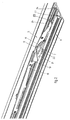
- Figs. 2 - 17 show one of said operating mechanisms 5 in more detail.
- Each operating mechanism 5 comprises a link plate 10, which is attached to the stiffening frame of panel 4 in a well-known manner.
- Link plate 10 is in engagement with slide 7 for the purpose of effecting the movements of panel 4.
- the link plate 10 includes a link rib 11 on one side, around which link cams 12, 13 of slide 7 engage.
- Both the link cams 12, 13 and the link rib 11 are formed by enveloping (laterally flanged) metal parts of link plate 10 and slide 7, respectively, in plastic by means of an injection moulding process, as a result of which a very solid construction is obtained without any loose parts that require additional mounting steps.
- the open roof construction furthermore includes a locking mechanism for locking panel 4 in its closed position, in particular on the rear side thereof, on the one hand in order to seal the panel properly against the fixed roof 1 and on the other hand in order to protect the panel from being broken open on the rear side.
- the locking mechanism includes a locking pin 14 formed on or attached to stationary guide rail 6, which comes into engagement in the closed position of the panel with a locking slot 15, which is formed in an elongate locking element 16.
- link cams 12, 13, included in the operating mechanism are formed such that link rib 11, included as well in the operating mechanism, capable of movement between cams 12, 13, whilst link plate 10 undergoes angular displacement simultaneously therewith, without any play being created between rib 11 and cams 12, 13 as long as pin 14 is not in engagement with slot 15 yet.
- the thickness of link rib 11 decreases, as a result of which some play is created between rib 11 and cams 12, 13.
- the advantage of this is that the same mechanism can be used with open roof constructions having straight guide rails 6 and open roof constructions having curved guide rails 6. The play between rib 11 and cams 12, 13 offsets this.
- Locking element 16 is movable along link plate 10 by means of a longitudinal guide (not shown), and at the front end it is in engagement with a slot 18 in link plate 10 by means of a pin 17. Said slot 18 defines the adjusting range of locking element 16.
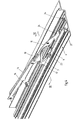
- Pin 17 also serves to provide the pivoted connection with a connecting arm 19, which is pivotally connected to slide 7 at its lower end by means of a pivot 20.
- Said pivoting arm 19 not only functions to actuate locking element 16, but also to support panel 4, in particular in the raised position thereof.
- the connecting arm 19 extends at least substantially vertically, or at least substantially perpendicularly to panel 4, so that forces being exerted on said panel can be directly transmitted to guide rail 6 by the connecting arm 19, substantially without any flexural forces being exerted on connecting arm 19. Since the connecting arm 19 is mounted on the side of link plate 10 remote from link rib 11, no disadvantageous torques will develop on link plate 10 when forces are exerted on panel 4, since link plate 10 is supported on both sides.
- the pivoting movement of connecting arm 19 upon actuation of the locking element 16 automatically provides a reduction between the driving slide 7 and locking element 16, as a result of which only a short slot 18 in link plate 10 is required, so that a strong and compact construction is obtained.
- Locking recess 23 slopes upwards in forward direction.
- Locking element 21 is controlled by slide 7.
- a cam 35 is formed on slide 7 (see figures 7-10), preferably by enveloping a flanged metal part of slide 7 in plastic by means of an injection moulding process.
- the elongated locking element 21 includes an elongate control slot 36, with which cam 35 is in constant engagement.
- locking element 21 extends horizontally and locking cam 22 is retained in vertical direction in a groove 37 of guide rail 6.
- Cam 35 is retained in horizontal direction in a deflected part 36' of slot 36, so that locking element 21 is locked in position with respect to slide 7 and moves along with said slide.
- cam 22 In the frontmost position of panel 4 cam 22 can move upwards in the locking recess, thus enabling movement of cam 35 through slot 36 simultaneously with the downward pivoting movement of locking element 21. Said locking element is more or less locked in position with respect to guide rail 6 in that position.
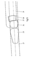
- a locking element 21 mates with a front sliding shoe of operating mechanism 5, which is capable of forward and backward sliding movement in guide rail 6.
- the front end 24 of link plate 10 includes integrated sliding shoes 25, which function as hinges for link plate 10 and which also function as front guides of operating mechanism 5 in guide rail 6.
- link plate 10 and the locking element 21 must allow each other's movements in vertical direction, therefore.
- locking element 21 and link plate 10 must abut against each other in such a manner as to be capable of transmitting large forces in horizontal direction.
- Figs. 12 - 15 show the front end 24 of link plate 10 and the front end of locking element 21. As can be seen in the figure, the rear part of sliding shoe 25 has been left out on one side of the front end 24 of link plate 10, so as to make room for locking element 21.
- Figs. 13 - 15 show that the front surface of locking element 21 abuts against the rear side of sliding shoe 25 in every position.
- a hinged cam 25 is formed, which also functions as a sliding shoe for the front end of locking element 21 and to guide the front end of locking element 21 in vertical direction.
- link plate 10 is provided with a guide cam 27 at least substantially in the form of a segment of a circle, which guide cam is movable in a recess 28 in locking element 21 at least substantially in the form of a segment of a circle.
- Both locking element 21 and link plate 10 are capable of pivoting movement with respect to link plate 10 and locking element 21, respectively, via unround sliding shoes.
- locking element 21 will also be urged slightly rearwards when pivoting downwards during the first upward pivoting movement of panel 4.
- the front sliding shoe 25 and thus panel 4 are moved rearwards, thus providing a correction movement for the front side of panel 4 so as to prevent the seal of panel 4 being damaged.
- Figs. 16 and 17 show in more detail slide 7 and the associated driving cable 8, and in particular the mating parts thereof.
- a coupling element 29 is formed on the end of cable 8, in particular by forming plastic thereon by means of an injection moulding process.
- Said coupling element 29 is comprised of a laterally projecting block 30, in which an groove 31 that is open on the upper side is formed in the longitudinal direction thereof.
- Block 30 fits in a recess 32 in the underside of slide 7.
- Said recess is formed in the front part of slide 7, slightly ahead of the control cam 35 for locking element 21.
- the invention provides an open roof construction which is remarkable for the simplicity and stability of the construction, which comprises few parts and which is easy to install.
- the invention is not limited to the embodiment as described above and shown in the drawing, which can be varied in several ways without departing from the scope of the invention.
- the locking slot and the locking pin or cam could also be reversed kinematically.
- a pivoting element as a locking element.
- the invention can be used with open roof constructions having other operating mechanisms such as pin-slot actuators, or lifting mechanisms having link structures or the like.
Claims (7)
- Structure de toit ouvrant pour un véhicule ayant une ouverture (2) dans son toit fixe (1), comprenant une partie fixe (3) devant être fixée sur le toit, ladite partie fixe inclut au moins un rail de guidage (6) fixe sur le bord de l'ouverture du toit, qui s'étend dans la direction longitudinale du véhicule, au moins un panneau (4) réglable supporté par ladite partie fixe, qui peut être réglé entre une position fermée, dans laquelle il ferme l'ouverture du toit, et une position ouverte dans laquelle il a été déplacé vers l'arrière dans une position inclinée vers le haut au moins partiellement au-dessus du toit fixe, position dans laquelle il ouvre l'ouverture du toit au moins partiellement, un mécanisme de commande (5) étant fourni pour régler ledit panneau, ledit mécanisme de commande est raccordé à une glissière (7) entraínée et comprend un élément de panneau (10), de préférence une plaque de raccordement, qui est fixée sur le panneau (4) et qui est raccordée de manière réglable à ladite glissière (7), ledit élément de panneau (10) est supporté de manière pivotante et coulissante sur le côté avant par rapport audit rail de guidage (6) fixe, un mécanisme de fermeture (14 - 16) étant également fourni, ledit mécanisme comprend un élément de verrouillage (16) qui est raccordé de manière coulissante à l'élément de panneau, ledit élément de verrouillage peut être verrouillé sur le rail de guidage (6) dans la position fermée du panneau, de préférence par l'intermédiaire d'un raccord à cames et à fentes (14, 15), et qui peut être actionné au moyen d'un bras de raccordement (19) qui est raccordé à ladite glissière (7), ledit bras de raccordement (19) étant raccordé de manière coulissante et pivotante à l'élément de panneau (10), afin que le bras de raccordement (19) s'étende au moins sensiblement verticalement dans la position pivotée vers le haut du panneau (4), caractérisée en ce que le bras de raccordement (19) supporte le panneau (4) sur un côté latéral de l'élément de panneau (10) opposé au côté sur lequel les autres éléments du mécanisme de commande (5) sont pivotés.
- Structure de toit ouvrant selon la revendication 1, dans laquelle le mécanisme de commande (5) comprend un raccord à cames de liaison (11 - 13) interconnectant ladite glissière (7) et ledit élément de panneau (10) et muni d'une nervure de liaison (11) formée sur un côté de l'élément de panneau (10) et de cames de liaison (12 - 13) formées sur ladite glissière (7), lesdites cames de liaison s'engageant autour de ladite nervure de liaison, alors que ledit bras de raccordement (19) est disposé sur le côté opposé dudit élément de panneau (10).
- Structure de toit ouvrant selon la revendication 1 ou 2, dans laquelle ledit bras de raccordement (19) est guidé dans une fente (18) formée dans ledit élément de panneau (10) au moyen d'un axe (17).
- Structure de toit ouvrant selon la revendication 3, dans laquelle ledit élément de verrouillage (16) est raccordé à l'axe (17) du bras de raccordement (19).
- Structure de toit ouvrant selon l'une quelconque des revendications précédentes, dans laquelle l'élément de verrouillage (16) inclut une fente de verrouillage (15) s'étendant en partie verticalement près de son extrémité arrière, avec laquelle une goupille d'arrêt (14) formée sur ledit rail de guidage (6) fixe peut venir en prise près de la position fermée dudit panneau (4).
- Structure de toit ouvrant selon l'une quelconque des revendications précédentes, dans laquelle ledit bras de raccordement (19) coopère directement avec ladite glissière (7) par l'intermédiaire d'un pivot.
- Structure de toit ouvrant selon l'une quelconque des revendications précédentes, dans laquelle le bras de raccordement (19) occupe une position sensiblement horizontale dans la position fermée du panneau (4) et dans laquelle le bras de raccordement (19) peut être pivoté vers le haut quand le panneau est déplacé depuis sa position fermée, agissant ainsi comme un élément de retardement entre ladite glissière (7) et ledit élément de verrouillage (16), à la suite de quoi le mouvement de la glissière (7) est converti en un mouvement longitudinal plus petit dudit élément de verrouillage (16), au moins durant une partie de l'actionnement de l'élément de verrouillage.
Applications Claiming Priority (4)
| Application Number | Priority Date | Filing Date | Title |
|---|---|---|---|
| NL1013443 | 1999-11-01 | ||
| NL1013443 | 1999-11-01 | ||
| NL1013756A NL1013756C2 (nl) | 1999-11-01 | 1999-12-06 | Open-dakconstructie voor een voertuig. |
| NL1013756 | 1999-12-06 |
Publications (2)
| Publication Number | Publication Date |
|---|---|
| EP1095807A1 EP1095807A1 (fr) | 2001-05-02 |
| EP1095807B1 true EP1095807B1 (fr) | 2005-11-16 |
Family
ID=26643076
Family Applications (1)
| Application Number | Title | Priority Date | Filing Date |
|---|---|---|---|
| EP00203729A Expired - Lifetime EP1095807B1 (fr) | 1999-11-01 | 2000-10-26 | Construction de toit ouvrant pour véhicule |
Country Status (5)
| Country | Link |
|---|---|
| US (1) | US6513866B1 (fr) |
| EP (1) | EP1095807B1 (fr) |
| JP (1) | JP4703834B2 (fr) |
| DE (1) | DE60024035T2 (fr) |
| NL (1) | NL1013756C2 (fr) |
Families Citing this family (18)
| Publication number | Priority date | Publication date | Assignee | Title |
|---|---|---|---|---|
| US7055898B2 (en) * | 2002-04-12 | 2006-06-06 | Inalfa Roof Systems Group B.V. | Roof assembly for a vehicle |
| DE60213202T2 (de) | 2002-05-03 | 2007-07-19 | Inalfa Roof Systems Group B.V. | Öffnungsfähige Dachkonstruktion für ein Fahrzeug und Verfahren für die Betätigung eines zugehörigen Schliesselementes |
| US6695398B2 (en) | 2002-06-13 | 2004-02-24 | Webasto Sunroofs, Inc. | Spoiler sunroof mechanism |
| DE10254774B4 (de) * | 2002-11-22 | 2005-07-21 | Webasto Ag | Fahrzeugdach |
| EP1634746A1 (fr) * | 2004-09-14 | 2006-03-15 | Grupo Antolin-Ingenieria, S.A. | Dispositif d'occulation à lamelles pour un pavillon de véhicule |
| EP1747928A1 (fr) * | 2005-07-28 | 2007-01-31 | ArvinMeritor GmbH | Système de coulissement pour un pare-soleil de véhicule |
| CN102300732B (zh) * | 2009-02-03 | 2014-04-16 | 银娜珐天窗系统集团股份有限公司 | 用于车辆的车顶组件 |
| DE102009043130B4 (de) * | 2009-09-25 | 2011-09-01 | Webasto Ag | Schiebedeckelanordnung |
| US8297692B2 (en) | 2009-11-20 | 2012-10-30 | AISIN Technical Center of America, Inc. | Tiltable sun roof for vehicles |
| US20120110912A1 (en) * | 2010-11-09 | 2012-05-10 | Webasto Roof Systems Inc. | High strength mechanism interface |
| DE102011085177B4 (de) * | 2011-10-25 | 2013-05-08 | Bos Gmbh & Co. Kg | Antriebssystem für ein KFZ-Dachsystem |
| DE102012010148B4 (de) * | 2012-05-24 | 2014-03-13 | Webasto SE | Seitenblende eines Deckels an einem Fahrzeugdach |
| DE102012223709A1 (de) * | 2012-11-29 | 2014-06-05 | Bos Gmbh & Co. Kg | Dachsystem für ein Kraftfahrzeug |
| DE102015211220B4 (de) * | 2015-06-18 | 2021-07-29 | Bos Gmbh & Co. Kg | Dachteileinheit für ein Kraftfahrzeug-Schiebedachsystem |
| DE102016119451A1 (de) * | 2016-10-12 | 2018-04-12 | Roof Systems Germany Gmbh | Kraftfahrzeug-Schiebedachsystem |
| EP3647094B1 (fr) | 2018-11-05 | 2022-10-26 | Inalfa Roof Systems Group B.V. | Système de toit pour véhicule |
| JP7388046B2 (ja) * | 2019-08-26 | 2023-11-29 | 株式会社アイシン | サンルーフ装置の駆動シューの製造方法 |
| EP3792091B1 (fr) | 2019-09-10 | 2022-06-15 | Inalfa Roof Systems Group B.V. | Ensemble de toiture pour véhicule et procédé d'assemblage |
Family Cites Families (4)
| Publication number | Priority date | Publication date | Assignee | Title |
|---|---|---|---|---|
| DE3408056A1 (de) * | 1984-03-05 | 1985-09-05 | Webasto-Werk W. Baier GmbH & Co, 8035 Gauting | Hebeschiebedach fuer fahrzeuge |
| US5325585A (en) * | 1991-09-05 | 1994-07-05 | Mazda Motor Corporation | Method for the assembly of a sun roof of an automotive vehicle |
| NL9101707A (nl) * | 1991-10-14 | 1993-05-03 | Vermeulen Hollandia Octrooien | Open-dakconstructie voor een voertuig. |
| IT1283433B1 (it) * | 1996-07-16 | 1998-04-21 | Autotek Srl | Dispositivo per l'azionamento di un tettuccio apribile di autoveicoli e simili |
-
1999
- 1999-12-06 NL NL1013756A patent/NL1013756C2/nl not_active IP Right Cessation
-
2000
- 2000-10-24 JP JP2000324468A patent/JP4703834B2/ja not_active Expired - Fee Related
- 2000-10-26 EP EP00203729A patent/EP1095807B1/fr not_active Expired - Lifetime
- 2000-10-26 DE DE60024035T patent/DE60024035T2/de not_active Expired - Lifetime
- 2000-10-31 US US09/702,429 patent/US6513866B1/en not_active Expired - Lifetime
Also Published As
| Publication number | Publication date |
|---|---|
| JP4703834B2 (ja) | 2011-06-15 |
| NL1013756C2 (nl) | 2001-05-02 |
| DE60024035D1 (de) | 2005-12-22 |
| DE60024035T2 (de) | 2006-08-10 |
| JP2001163060A (ja) | 2001-06-19 |
| EP1095807A1 (fr) | 2001-05-02 |
| US6513866B1 (en) | 2003-02-04 |
Similar Documents
| Publication | Publication Date | Title |
|---|---|---|
| EP1095807B1 (fr) | Construction de toit ouvrant pour véhicule | |
| EP0543427B1 (fr) | Construction de toit ouvrant pour véhicule | |
| EP1424234B1 (fr) | Structure de toit ouvrant pour véhicule | |
| EP1009644B1 (fr) | Procede d'ouverture et de fermeture d'un toit ouvrant dans un vehicule dont le toit fixe possede une ouverture et systeme de toit ouvrant | |
| EP1046529B1 (fr) | Construction de toit ouvrant pour véhicule | |
| US6957851B2 (en) | Open roof construction for a vehicle, and method of moving a closure element thereof | |
| US6419310B1 (en) | Open roof construction for a vehicle | |
| EP0955194B1 (fr) | Construction de toit ouvrant pour véhicule | |
| EP0140491B1 (fr) | Toit coulissant pour véhicules motorisés | |
| EP1494883B1 (fr) | Ensemble toit de vehicule | |
| US6012768A (en) | Open roof construction for a vehicle | |
| EP1488945B1 (fr) | Construction d'un toit ouvrant pour véhicule | |
| CA1326693C (fr) | Toit ouvrant-coulissant pour automobile | |
| EP1150852B1 (fr) | Structure de toit ouvrant de vehicule | |
| EP1046530A1 (fr) | Structure de toit ouvrant pour véhicule | |
| NL1013758C2 (nl) | Open-dakconstructie voor een voertuig. |
Legal Events
| Date | Code | Title | Description |
|---|---|---|---|
| PUAI | Public reference made under article 153(3) epc to a published international application that has entered the european phase |
Free format text: ORIGINAL CODE: 0009012 |
|
| AK | Designated contracting states |
Kind code of ref document: A1 Designated state(s): DE FR GB |
|
| AX | Request for extension of the european patent |
Free format text: AL;LT;LV;MK;RO;SI |
|
| 17P | Request for examination filed |
Effective date: 20011023 |
|
| AKX | Designation fees paid |
Free format text: DE FR GB |
|
| RAP1 | Party data changed (applicant data changed or rights of an application transferred) |
Owner name: INALFA ROOF SYSTEMS GROUP B.V. |
|
| 17Q | First examination report despatched |
Effective date: 20031125 |
|
| GRAP | Despatch of communication of intention to grant a patent |
Free format text: ORIGINAL CODE: EPIDOSNIGR1 |
|
| GRAS | Grant fee paid |
Free format text: ORIGINAL CODE: EPIDOSNIGR3 |
|
| GRAA | (expected) grant |
Free format text: ORIGINAL CODE: 0009210 |
|
| AK | Designated contracting states |
Kind code of ref document: B1 Designated state(s): DE FR GB |
|
| REG | Reference to a national code |
Ref country code: GB Ref legal event code: FG4D |
|
| REF | Corresponds to: |
Ref document number: 60024035 Country of ref document: DE Date of ref document: 20051222 Kind code of ref document: P |
|
| ET | Fr: translation filed | ||
| PLBE | No opposition filed within time limit |
Free format text: ORIGINAL CODE: 0009261 |
|
| STAA | Information on the status of an ep patent application or granted ep patent |
Free format text: STATUS: NO OPPOSITION FILED WITHIN TIME LIMIT |
|
| 26N | No opposition filed |
Effective date: 20060817 |
|
| PGFP | Annual fee paid to national office [announced via postgrant information from national office to epo] |
Ref country code: GB Payment date: 20081023 Year of fee payment: 9 |
|
| PG25 | Lapsed in a contracting state [announced via postgrant information from national office to epo] |
Ref country code: GB Free format text: LAPSE BECAUSE OF NON-PAYMENT OF DUE FEES Effective date: 20091026 |
|
| PGFP | Annual fee paid to national office [announced via postgrant information from national office to epo] |
Ref country code: FR Payment date: 20131031 Year of fee payment: 14 |
|
| REG | Reference to a national code |
Ref country code: FR Ref legal event code: ST Effective date: 20150630 |
|
| PG25 | Lapsed in a contracting state [announced via postgrant information from national office to epo] |
Ref country code: FR Free format text: LAPSE BECAUSE OF NON-PAYMENT OF DUE FEES Effective date: 20141031 |
|
| PGFP | Annual fee paid to national office [announced via postgrant information from national office to epo] |
Ref country code: DE Payment date: 20191029 Year of fee payment: 20 |
|
| REG | Reference to a national code |
Ref country code: DE Ref legal event code: R071 Ref document number: 60024035 Country of ref document: DE |