EP1095551A1 - Machine agricole - Google Patents
Machine agricole Download PDFInfo
- Publication number
- EP1095551A1 EP1095551A1 EP00123251A EP00123251A EP1095551A1 EP 1095551 A1 EP1095551 A1 EP 1095551A1 EP 00123251 A EP00123251 A EP 00123251A EP 00123251 A EP00123251 A EP 00123251A EP 1095551 A1 EP1095551 A1 EP 1095551A1
- Authority
- EP
- European Patent Office
- Prior art keywords
- hydraulic cylinder
- agricultural machine
- wheel
- support
- working
- Prior art date
- Legal status (The legal status is an assumption and is not a legal conclusion. Google has not performed a legal analysis and makes no representation as to the accuracy of the status listed.)
- Granted
Links
Images


Classifications
-
- A—HUMAN NECESSITIES
- A01—AGRICULTURE; FORESTRY; ANIMAL HUSBANDRY; HUNTING; TRAPPING; FISHING
- A01B—SOIL WORKING IN AGRICULTURE OR FORESTRY; PARTS, DETAILS, OR ACCESSORIES OF AGRICULTURAL MACHINES OR IMPLEMENTS, IN GENERAL
- A01B73/00—Means or arrangements to facilitate transportation of agricultural machines or implements, e.g. folding frames to reduce overall width
- A01B73/005—Means or arrangements to facilitate transportation of agricultural machines or implements, e.g. folding frames to reduce overall width for endwise transportation, i.e. the direction of transport being substantially perpendicular to the direction of agricultural operation
Definitions
- the invention relates to an agricultural machine according to the preamble of the claim 1.
- mowers are Widely used in practice for rear three-point attachment. To increase the area coverage the demand for mowers with a larger working width has increased.
- Such mowers are placed in a position behind the for road transport Tug swiveled.
- the focus is far from the tractor rear axle removed so that the front axle is relieved, and the steering behavior of the tractor becomes insecure.
- mowers with one are already Jockey wheel known, via which the machine weight in both working and is also supported in the transport position.
- This jockey wheel must be in the working position be designed as a self-steering trailing wheel while it is in the transport position should be fixed in such a way that it can take control of the mower.
- the swivel joint between the mounting frame and the mower is in the transport position not fixed, so that the mower is guided through the support wheel like a single-axle trailer runs behind the tractor and does not veer sideways when cornering.
- the support wheel In working position the support wheel must be located behind the mower so that it does not runs in the feed. In the transport position, however, it can for a better weight distribution Advantageously, it can also be arranged centrally behind the machine. That far laterally protruding mower is at risk from hitting obstacles because of Tug driver only the side distance of the outer edge of the mower to an obstacle difficult to estimate. A so-called collision protection is therefore necessary which automatically swings the mower backwards when it hits it an obstacle.
- collision protection is therefore necessary which automatically swings the mower backwards when it hits it an obstacle.
- For the necessary adjustment processes such as lifting the mower, possible change of position of the support wheel, locking of the support wheel swivel axis and fixing or releasing the swivel axis between the mower and mounting brackets are extensive hydraulic control elements, which in a certain Sequence must be operated, required.
- the fixing device for the support wheel axis is only dependent on it actuated in the sense of a determination of the jockey wheel axis, whether the wheel boom its Transport position has reached relative to the support arm or not.
- the fixing device is from the wheel arm controlled positive alignment mechanism.
- the invention has for its object an easy to use, reliable and economically producible agricultural machine of the aforementioned Kind of design.
- the operative connection ensures that the jockey wheel axis is then reliably fixed is when the work unit is lifted and the locking device is deliberately released are. On the other hand, the jockey wheel remains in all other operating states of the machine self-steering.
- the fixing device is actuated functionally simply by a hydraulic cylinder.
- the hydraulic cylinder for the fixing device is expediently hydraulic with the Pressurization of the lifting cylinder of the work unit coupled such that the hydraulic cylinder under the high pressure that is already present also sets the jockey wheel axis for lifting the work unit.
- the jockey wheel does not run in the standing position when the machine is in the working position or collides with obstacles, it is behind the work unit by means of the wheel carrier positioned. During the transport run, this is then determined in its running direction Jockey wheel on the wheel carrier pivoted approximately in the longitudinal direction of the machine in Direction of travel of the towing vehicle.
- the hydraulic connection with regard to the desired safety aspect of the Fixing device advantageously contains a control valve that is only in the transport position of the wheel carrier enables the hydraulic cylinder to be acted upon. In the working position of the wheel carrier, however, is the inflow to the hydraulic cylinder blocked. Since the oil can then drain out of the hydraulic cylinder, the fixing device remains reliably disengaged.
- control valve is also provided with an actuating device for the locking device connected.
- the locking device fixes the machine in the Working position in the laterally protruding position.
- the oil flow to the hydraulic cylinder is then locked so that the fixing device is passive.
- With the locking device released the oil flow to the hydraulic cylinder is free, so that the pressurization pressure the lifting cylinder defines the support wheel axis. It is assumed that the Locking device is deliberately released, and not only addressed as collision protection Has.
- the wheel carrier is expediently in the transport position blocked when the work unit is or is being lifted. This helps Damage due to excessive, due to the weight of the work unit To avoid forces.
- This is structurally simple by blocking the wheel carrier adjusting, double-acting hydraulic cylinder.
- a valve is useful for this provided that with the lifting pressure of the lifting cylinder in a locked position piloted and used in a working line of the hydraulic cylinder, which is responsible for setting and maintaining the transport position.
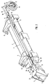
- An agricultural machine here a mounted mower, the Fig. 1 to 3, is with a mounting frame 1 to the three-point lifting device, not shown Tractor connected.
- a mounting frame 1 With the mounting frame 1 is on a vertical hinge axis 2 a support arm 3 connected to which on a horizontal axis 5 Mower deck 4 is articulated.
- a work unit 7 (a mower unit) is with handlebars 6 guided vertically.
- the hydraulic cylinder 8 as a lifting cylinder and the link 6 form actuators for the mower unit.
- On the mower deck 4 is in a vertical pivot axis 9 Wheel carrier 10 articulated.
- the wheel carrier 10 is via a double-acting hydraulic cylinder 11 from a working position (Fig. 1) in a transport position (Fig. 2) and reversely adjustable.
- a rotatable support wheel axis 12 is mounted a support wheel 13 carries.
- a double lever firmly connected to the support wheel axis 12 14 are offset by 180 ° two control rollers 15 mounted.
- On the wheel carrier 10 is a supported in this embodiment single-acting hydraulic cylinder 16, the over a pressure plate 17 can interact with both control rollers 15.
- This Components form a fixing device for the support wheel axis 12 the hydraulic cylinder 16 adjustable pressure plate 17 can be controlled by the control rollers 15 the otherwise freely rotatable support wheel axis 12 in a suitable for the transport trip Set and set the direction (Fig. 3).
- the support arm 3 is in the working position shown in Fig. 1 with a locking device 18 fixed around the hinge axis 2 on the mounting frame 1.
- the locking device 8 has a lever-shaped carrier 22 ', which is about an approximately vertical axis 19
- Support arm 3 is pivotable and carries a locking roller 20.
- On the mounting frame 1 is a catch hook 21 is mounted, which has a contact surface for the engaging in the catch hook 21 Has locking roller 20.
- This contact surface of the catch hook 21 is with a small angle relative to the line of action of the locking roller around the Joint axis 2 inclined so that the locking device 18 against the force of a Trigger locking roller 20 against pressure spring 22 pressing the contact surface can, if the work unit 7 drives against an obstacle (collision protection).
- the locking device 18 is also via tie rods 23 and 24 with the wheel carrier 10 connected such that when pivoting the wheel carrier 10 in the direction of Transport position (Fig. 2) in the locking device 18 of the carrier 22 'with the locking roller 20 pivots against the force of the compression spring 22 about the axis 19, whereby the locking roller 20 is disengaged from the hook 21 and the mower released about the hinge axis 2 for pivoting movement in the direction of the transport position becomes. In this way, the locking device can be released deliberately.
- a control valve In a hydraulic line, not shown, between the hydraulic cylinders 8 for lifting of the mower and the hydraulic cylinder 16 of the fixing device for the Jockey wheel axis 12, a control valve, not shown, can be switched on with the locking device 18 released, an oil flow is permitted in both directions. At locked locking device 18, the control valve blocks the oil supply to the hydraulic cylinder 16. The outflow of oil from the hydraulic cylinder 16 is still possible.
- the control valve ensures that when the mower is lowered, the Fixing the support wheel axis 12 is canceled while the support wheel axis at Lifting out the mower and released locking device in the transport position is blocked and aligned. In the working position, the support wheel axis 12 is freely rotatable, so that the support wheel 13 when cornering and also when turning and maneuvering with the mower raised on the headlands always self-steering into the respective one Can set the direction of travel.
- the wheel carrier 10 can be locked in its transport position by the Actuating, double-acting hydraulic cylinder 11 is blocked hydraulically.
- the Hydraulic cylinder 11 is via a valve device 25 in the respective direction of movement controlled.
- a valve 26 In a working line to the hydraulic cylinder 11, which is used for pressurization responsible for pivoting the wheel carrier 10 in the transport position is a valve 26 is arranged, for example a 2/2-way valve, the is switchable by a spring 30 into a through position (shown), and by a hydraulic pilot control 29 can be brought into a locked position against the spring 30 is.
- the hydraulic pilot control 29 is connected to a pressure supply via a pilot line 28 27 at least one lifting cylinder 8 connected.
- valve 26 switches in the locked position so that the hydraulic cylinder 11 is hydraulically blocked. As soon as the working unit 7 is lowered and the lifting cylinder 8 is depressurized, the valve goes 26 automatically by the force of the spring 30 in the passage position shown, so that the hydraulic cylinder 11 can be controlled as desired.
- the valve 26 could be a solenoid valve that connects the lifting cylinder 8 with a controlling solenoid valve is electrically coupled.
Landscapes
- Life Sciences & Earth Sciences (AREA)
- Engineering & Computer Science (AREA)
- Mechanical Engineering (AREA)
- Soil Sciences (AREA)
- Environmental Sciences (AREA)
- Harvester Elements (AREA)
Applications Claiming Priority (2)
| Application Number | Priority Date | Filing Date | Title |
|---|---|---|---|
| DE29919026U DE29919026U1 (de) | 1999-10-29 | 1999-10-29 | Landwirtschaftliche Maschine, insbesondere Anbaumähwerk mit großer Arbeitsbreite |
| DE29919026U | 1999-10-29 |
Publications (2)
| Publication Number | Publication Date |
|---|---|
| EP1095551A1 true EP1095551A1 (fr) | 2001-05-02 |
| EP1095551B1 EP1095551B1 (fr) | 2004-04-14 |
Family
ID=8080916
Family Applications (1)
| Application Number | Title | Priority Date | Filing Date |
|---|---|---|---|
| EP00123251A Expired - Lifetime EP1095551B1 (fr) | 1999-10-29 | 2000-10-26 | Machine agricole |
Country Status (2)
| Country | Link |
|---|---|
| EP (1) | EP1095551B1 (fr) |
| DE (2) | DE29919026U1 (fr) |
Cited By (1)
| Publication number | Priority date | Publication date | Assignee | Title |
|---|---|---|---|---|
| CN102577681A (zh) * | 2011-12-30 | 2012-07-18 | 东北农业大学 | 大型农机具地轮作业状态与运输状态转换结构 |
Families Citing this family (1)
| Publication number | Priority date | Publication date | Assignee | Title |
|---|---|---|---|---|
| GB2601822B (en) * | 2020-12-14 | 2024-04-24 | Wessex Int Machinery | Apparatus for towing behind a vehicle |
Citations (6)
| Publication number | Priority date | Publication date | Assignee | Title |
|---|---|---|---|---|
| GB2082436A (en) * | 1980-08-26 | 1982-03-10 | Poettinger Alois Maschf | A connector device for an agricultural machine |
| US4682462A (en) * | 1985-10-04 | 1987-07-28 | Johnson Sr Gerald T | Swather with swinging hitch |
| DE3641546A1 (de) * | 1986-12-05 | 1988-06-16 | Claas Saulgau Gmbh | Verschwenkvorrichtung fuer landwirtschaftliche anbaugeraete besonders maehwerke |
| US4768334A (en) * | 1987-06-15 | 1988-09-06 | Honey Bee Manufacturing Ltd. | Tractor mounted swather |
| EP0486413A1 (fr) * | 1990-11-12 | 1992-05-20 | Kuhn S.A. | Machine de récolte, notamment faucheuse, pouvant être amenée aisément d'une position de travail dans une position de transport |
| FR2691319A1 (fr) * | 1992-05-14 | 1993-11-26 | Kuhn Sa | Machine agricole, notamment faucheuse, comportant un dispositif de transmission de mouvement avec une circulation forcée du lubrifiant. |
-
1999
- 1999-10-29 DE DE29919026U patent/DE29919026U1/de not_active Expired - Lifetime
-
2000
- 2000-10-26 EP EP00123251A patent/EP1095551B1/fr not_active Expired - Lifetime
- 2000-10-26 DE DE50006051T patent/DE50006051D1/de not_active Expired - Lifetime
Patent Citations (6)
| Publication number | Priority date | Publication date | Assignee | Title |
|---|---|---|---|---|
| GB2082436A (en) * | 1980-08-26 | 1982-03-10 | Poettinger Alois Maschf | A connector device for an agricultural machine |
| US4682462A (en) * | 1985-10-04 | 1987-07-28 | Johnson Sr Gerald T | Swather with swinging hitch |
| DE3641546A1 (de) * | 1986-12-05 | 1988-06-16 | Claas Saulgau Gmbh | Verschwenkvorrichtung fuer landwirtschaftliche anbaugeraete besonders maehwerke |
| US4768334A (en) * | 1987-06-15 | 1988-09-06 | Honey Bee Manufacturing Ltd. | Tractor mounted swather |
| EP0486413A1 (fr) * | 1990-11-12 | 1992-05-20 | Kuhn S.A. | Machine de récolte, notamment faucheuse, pouvant être amenée aisément d'une position de travail dans une position de transport |
| FR2691319A1 (fr) * | 1992-05-14 | 1993-11-26 | Kuhn Sa | Machine agricole, notamment faucheuse, comportant un dispositif de transmission de mouvement avec une circulation forcée du lubrifiant. |
Cited By (2)
| Publication number | Priority date | Publication date | Assignee | Title |
|---|---|---|---|---|
| CN102577681A (zh) * | 2011-12-30 | 2012-07-18 | 东北农业大学 | 大型农机具地轮作业状态与运输状态转换结构 |
| CN102577681B (zh) * | 2011-12-30 | 2014-11-26 | 东北农业大学 | 大型农机具地轮作业状态与运输状态转换结构 |
Also Published As
| Publication number | Publication date |
|---|---|
| EP1095551B1 (fr) | 2004-04-14 |
| DE50006051D1 (de) | 2004-05-19 |
| DE29919026U1 (de) | 2000-02-03 |
Similar Documents
| Publication | Publication Date | Title |
|---|---|---|
| DE2715375C3 (de) | Stellvorrichtung für ein landwirtschaftlich nutzbares Arbeitsgerät | |
| DE2737053C3 (de) | Landwirtschaftlich nutzbares Arbeitsgerät | |
| EP2186713B1 (fr) | Dispositif de ballastage et véhicule agricole équipé avec ce dernier | |
| DD229572A5 (de) | Geraetetraeger mit mindestens einem seitenrahmen | |
| DE2948899A1 (de) | Fahrzeug mit geraete-schnellkuppler | |
| DE19959484A1 (de) | Mähgerät | |
| EP0567960B1 (fr) | Attelage de remorque pour traîner deux appareils | |
| EP0019275A2 (fr) | Charrue tourne-oreille | |
| DE8807054U1 (de) | Heuwerbungsmaschine | |
| DE19534695C2 (de) | An einem Schlepper ansetzbares Heckmähwerk | |
| EP2042410B1 (fr) | Véhicule agricole | |
| AT516017B1 (de) | Fahrzeuganhänger mit einer hydraulisch lenkbaren Deichsel | |
| EP1095551B1 (fr) | Machine agricole | |
| DE69419341T2 (de) | Bodenbearbeitungsmaschine | |
| DE102010022246B4 (de) | Landwirtschaftliches Anbaugerät | |
| DE2220585A1 (de) | Vorrichtung zum Verstellen eines an die Kupplungsvorrichtung eines Schleppers anschliessbaren Arbeitsgeraetes,insbesondere Bodenbearbeitungsgeraet | |
| DE19820377C1 (de) | Arbeitsfahrzeug mit kippbarer Fahrerplattform und Kippvorrichtung | |
| DE3032112C2 (de) | Anschlußvorrichtung zum Anbringen von landwirtschaftlichen Arbeitsmaschinen an einer Zugmaschine | |
| DE2615497C3 (de) | Zugdeichselanordnung für schleppergezogene landwirtschaftliche Maschine | |
| DE69402214T2 (de) | Einrichtung an einem schleppergezogenen Werkzeug | |
| DE19608579C2 (de) | Anhängevorrichtung | |
| DE29600075U1 (de) | Pflug | |
| DE2349176B2 (de) | Mähschwader | |
| EP1095550B1 (fr) | Machine agricole | |
| DE20012446U1 (de) | Landwirtschaftliche Maschine |
Legal Events
| Date | Code | Title | Description |
|---|---|---|---|
| PUAI | Public reference made under article 153(3) epc to a published international application that has entered the european phase |
Free format text: ORIGINAL CODE: 0009012 |
|
| AK | Designated contracting states |
Kind code of ref document: A1 Designated state(s): DE FR NL |
|
| AX | Request for extension of the european patent |
Free format text: AL;LT;LV;MK;RO;SI |
|
| 17P | Request for examination filed |
Effective date: 20010907 |
|
| 17Q | First examination report despatched |
Effective date: 20011127 |
|
| AKX | Designation fees paid |
Free format text: DE FR NL |
|
| 111Z | Information provided on other rights and legal means of execution |
Free format text: 20020412 DE FR NL |
|
| GRAP | Despatch of communication of intention to grant a patent |
Free format text: ORIGINAL CODE: EPIDOSNIGR1 |
|
| GRAS | Grant fee paid |
Free format text: ORIGINAL CODE: EPIDOSNIGR3 |
|
| GRAA | (expected) grant |
Free format text: ORIGINAL CODE: 0009210 |
|
| AK | Designated contracting states |
Kind code of ref document: B1 Designated state(s): DE FR NL |
|
| REF | Corresponds to: |
Ref document number: 50006051 Country of ref document: DE Date of ref document: 20040519 Kind code of ref document: P |
|
| ET | Fr: translation filed | ||
| PLBE | No opposition filed within time limit |
Free format text: ORIGINAL CODE: 0009261 |
|
| STAA | Information on the status of an ep patent application or granted ep patent |
Free format text: STATUS: NO OPPOSITION FILED WITHIN TIME LIMIT |
|
| 26N | No opposition filed |
Effective date: 20050117 |
|
| NLS | Nl: assignments of ep-patents |
Owner name: FELLA BETEILIGUNGS GMBH Effective date: 20080108 Owner name: FELLA-WERKE GMBH Effective date: 20080108 |
|
| REG | Reference to a national code |
Ref country code: FR Ref legal event code: TP |
|
| REG | Reference to a national code |
Ref country code: FR Ref legal event code: PLFP Year of fee payment: 16 |
|
| REG | Reference to a national code |
Ref country code: DE Ref legal event code: R082 Ref document number: 50006051 Country of ref document: DE Representative=s name: GRUENECKER PATENT- UND RECHTSANWAELTE PARTG MB, DE Ref country code: DE Ref legal event code: R081 Ref document number: 50006051 Country of ref document: DE Owner name: AGCO FEUCHT GMBH, DE Free format text: FORMER OWNER: FELLA-WERKE GMBH, 90537 FEUCHT, DE |
|
| REG | Reference to a national code |
Ref country code: NL Ref legal event code: HC Owner name: AGCO FEUCHT GMBH; DE Free format text: DETAILS ASSIGNMENT: VERANDERING VAN EIGENAAR(S), VERANDERING VAN NAAM VAN DE EIGENAAR(S); FORMER OWNER NAME: FELLA-WERKE GMBH Effective date: 20160802 |
|
| REG | Reference to a national code |
Ref country code: FR Ref legal event code: PLFP Year of fee payment: 17 |
|
| PGFP | Annual fee paid to national office [announced via postgrant information from national office to epo] |
Ref country code: DE Payment date: 20161020 Year of fee payment: 17 Ref country code: NL Payment date: 20161019 Year of fee payment: 17 Ref country code: FR Payment date: 20161020 Year of fee payment: 17 |
|
| REG | Reference to a national code |
Ref country code: DE Ref legal event code: R119 Ref document number: 50006051 Country of ref document: DE |
|
| REG | Reference to a national code |
Ref country code: NL Ref legal event code: MM Effective date: 20171101 |
|
| REG | Reference to a national code |
Ref country code: FR Ref legal event code: ST Effective date: 20180629 |
|
| PG25 | Lapsed in a contracting state [announced via postgrant information from national office to epo] |
Ref country code: DE Free format text: LAPSE BECAUSE OF NON-PAYMENT OF DUE FEES Effective date: 20180501 Ref country code: NL Free format text: LAPSE BECAUSE OF NON-PAYMENT OF DUE FEES Effective date: 20171101 |
|
| PG25 | Lapsed in a contracting state [announced via postgrant information from national office to epo] |
Ref country code: FR Free format text: LAPSE BECAUSE OF NON-PAYMENT OF DUE FEES Effective date: 20171031 |