EP1093902A1 - Procédé de fabrication d'une armature cintrable - Google Patents
Procédé de fabrication d'une armature cintrable Download PDFInfo
- Publication number
- EP1093902A1 EP1093902A1 EP00402833A EP00402833A EP1093902A1 EP 1093902 A1 EP1093902 A1 EP 1093902A1 EP 00402833 A EP00402833 A EP 00402833A EP 00402833 A EP00402833 A EP 00402833A EP 1093902 A1 EP1093902 A1 EP 1093902A1
- Authority
- EP
- European Patent Office
- Prior art keywords
- frame
- pattern
- reinforcement
- profile
- calendering
- Prior art date
- Legal status (The legal status is an assumption and is not a legal conclusion. Google has not performed a legal analysis and makes no representation as to the accuracy of the status listed.)
- Granted
Links
Images


Classifications
-
- B—PERFORMING OPERATIONS; TRANSPORTING
- B29—WORKING OF PLASTICS; WORKING OF SUBSTANCES IN A PLASTIC STATE IN GENERAL
- B29C—SHAPING OR JOINING OF PLASTICS; SHAPING OF MATERIAL IN A PLASTIC STATE, NOT OTHERWISE PROVIDED FOR; AFTER-TREATMENT OF THE SHAPED PRODUCTS, e.g. REPAIRING
- B29C43/00—Compression moulding, i.e. applying external pressure to flow the moulding material; Apparatus therefor
- B29C43/22—Compression moulding, i.e. applying external pressure to flow the moulding material; Apparatus therefor of articles of indefinite length
- B29C43/224—Compression moulding, i.e. applying external pressure to flow the moulding material; Apparatus therefor of articles of indefinite length having a profiled section, e.g. tubes, rods
- B29C43/226—Compression moulding, i.e. applying external pressure to flow the moulding material; Apparatus therefor of articles of indefinite length having a profiled section, e.g. tubes, rods having a corrugated section
-
- B—PERFORMING OPERATIONS; TRANSPORTING
- B29—WORKING OF PLASTICS; WORKING OF SUBSTANCES IN A PLASTIC STATE IN GENERAL
- B29C—SHAPING OR JOINING OF PLASTICS; SHAPING OF MATERIAL IN A PLASTIC STATE, NOT OTHERWISE PROVIDED FOR; AFTER-TREATMENT OF THE SHAPED PRODUCTS, e.g. REPAIRING
- B29C43/00—Compression moulding, i.e. applying external pressure to flow the moulding material; Apparatus therefor
- B29C43/22—Compression moulding, i.e. applying external pressure to flow the moulding material; Apparatus therefor of articles of indefinite length
- B29C43/224—Compression moulding, i.e. applying external pressure to flow the moulding material; Apparatus therefor of articles of indefinite length having a profiled section, e.g. tubes, rods
-
- B—PERFORMING OPERATIONS; TRANSPORTING
- B29—WORKING OF PLASTICS; WORKING OF SUBSTANCES IN A PLASTIC STATE IN GENERAL
- B29C—SHAPING OR JOINING OF PLASTICS; SHAPING OF MATERIAL IN A PLASTIC STATE, NOT OTHERWISE PROVIDED FOR; AFTER-TREATMENT OF THE SHAPED PRODUCTS, e.g. REPAIRING
- B29C48/00—Extrusion moulding, i.e. expressing the moulding material through a die or nozzle which imparts the desired form; Apparatus therefor
- B29C48/001—Combinations of extrusion moulding with other shaping operations
-
- B—PERFORMING OPERATIONS; TRANSPORTING
- B29—WORKING OF PLASTICS; WORKING OF SUBSTANCES IN A PLASTIC STATE IN GENERAL
- B29C—SHAPING OR JOINING OF PLASTICS; SHAPING OF MATERIAL IN A PLASTIC STATE, NOT OTHERWISE PROVIDED FOR; AFTER-TREATMENT OF THE SHAPED PRODUCTS, e.g. REPAIRING
- B29C48/00—Extrusion moulding, i.e. expressing the moulding material through a die or nozzle which imparts the desired form; Apparatus therefor
- B29C48/03—Extrusion moulding, i.e. expressing the moulding material through a die or nozzle which imparts the desired form; Apparatus therefor characterised by the shape of the extruded material at extrusion
- B29C48/07—Flat, e.g. panels
- B29C48/08—Flat, e.g. panels flexible, e.g. films
-
- B—PERFORMING OPERATIONS; TRANSPORTING
- B29—WORKING OF PLASTICS; WORKING OF SUBSTANCES IN A PLASTIC STATE IN GENERAL
- B29C—SHAPING OR JOINING OF PLASTICS; SHAPING OF MATERIAL IN A PLASTIC STATE, NOT OTHERWISE PROVIDED FOR; AFTER-TREATMENT OF THE SHAPED PRODUCTS, e.g. REPAIRING
- B29C48/00—Extrusion moulding, i.e. expressing the moulding material through a die or nozzle which imparts the desired form; Apparatus therefor
- B29C48/15—Extrusion moulding, i.e. expressing the moulding material through a die or nozzle which imparts the desired form; Apparatus therefor incorporating preformed parts or layers, e.g. extrusion moulding around inserts
- B29C48/154—Coating solid articles, i.e. non-hollow articles
-
- B—PERFORMING OPERATIONS; TRANSPORTING
- B29—WORKING OF PLASTICS; WORKING OF SUBSTANCES IN A PLASTIC STATE IN GENERAL
- B29C—SHAPING OR JOINING OF PLASTICS; SHAPING OF MATERIAL IN A PLASTIC STATE, NOT OTHERWISE PROVIDED FOR; AFTER-TREATMENT OF THE SHAPED PRODUCTS, e.g. REPAIRING
- B29C48/00—Extrusion moulding, i.e. expressing the moulding material through a die or nozzle which imparts the desired form; Apparatus therefor
- B29C48/25—Component parts, details or accessories; Auxiliary operations
- B29C48/30—Extrusion nozzles or dies
- B29C48/304—Extrusion nozzles or dies specially adapted for bringing together components, e.g. melts within the die
-
- B—PERFORMING OPERATIONS; TRANSPORTING
- B29—WORKING OF PLASTICS; WORKING OF SUBSTANCES IN A PLASTIC STATE IN GENERAL
- B29C—SHAPING OR JOINING OF PLASTICS; SHAPING OF MATERIAL IN A PLASTIC STATE, NOT OTHERWISE PROVIDED FOR; AFTER-TREATMENT OF THE SHAPED PRODUCTS, e.g. REPAIRING
- B29C48/00—Extrusion moulding, i.e. expressing the moulding material through a die or nozzle which imparts the desired form; Apparatus therefor
- B29C48/25—Component parts, details or accessories; Auxiliary operations
- B29C48/30—Extrusion nozzles or dies
- B29C48/35—Extrusion nozzles or dies with rollers
-
- B—PERFORMING OPERATIONS; TRANSPORTING
- B60—VEHICLES IN GENERAL
- B60J—WINDOWS, WINDSCREENS, NON-FIXED ROOFS, DOORS, OR SIMILAR DEVICES FOR VEHICLES; REMOVABLE EXTERNAL PROTECTIVE COVERINGS SPECIALLY ADAPTED FOR VEHICLES
- B60J10/00—Sealing arrangements
- B60J10/15—Sealing arrangements characterised by the material
- B60J10/18—Sealing arrangements characterised by the material provided with reinforcements or inserts
-
- B—PERFORMING OPERATIONS; TRANSPORTING
- B29—WORKING OF PLASTICS; WORKING OF SUBSTANCES IN A PLASTIC STATE IN GENERAL
- B29C—SHAPING OR JOINING OF PLASTICS; SHAPING OF MATERIAL IN A PLASTIC STATE, NOT OTHERWISE PROVIDED FOR; AFTER-TREATMENT OF THE SHAPED PRODUCTS, e.g. REPAIRING
- B29C48/00—Extrusion moulding, i.e. expressing the moulding material through a die or nozzle which imparts the desired form; Apparatus therefor
- B29C48/001—Combinations of extrusion moulding with other shaping operations
- B29C48/0022—Combinations of extrusion moulding with other shaping operations combined with cutting
-
- B—PERFORMING OPERATIONS; TRANSPORTING
- B29—WORKING OF PLASTICS; WORKING OF SUBSTANCES IN A PLASTIC STATE IN GENERAL
- B29C—SHAPING OR JOINING OF PLASTICS; SHAPING OF MATERIAL IN A PLASTIC STATE, NOT OTHERWISE PROVIDED FOR; AFTER-TREATMENT OF THE SHAPED PRODUCTS, e.g. REPAIRING
- B29C48/00—Extrusion moulding, i.e. expressing the moulding material through a die or nozzle which imparts the desired form; Apparatus therefor
- B29C48/03—Extrusion moulding, i.e. expressing the moulding material through a die or nozzle which imparts the desired form; Apparatus therefor characterised by the shape of the extruded material at extrusion
- B29C48/12—Articles with an irregular circumference when viewed in cross-section, e.g. window profiles
-
- Y—GENERAL TAGGING OF NEW TECHNOLOGICAL DEVELOPMENTS; GENERAL TAGGING OF CROSS-SECTIONAL TECHNOLOGIES SPANNING OVER SEVERAL SECTIONS OF THE IPC; TECHNICAL SUBJECTS COVERED BY FORMER USPC CROSS-REFERENCE ART COLLECTIONS [XRACs] AND DIGESTS
- Y10—TECHNICAL SUBJECTS COVERED BY FORMER USPC
- Y10T—TECHNICAL SUBJECTS COVERED BY FORMER US CLASSIFICATION
- Y10T29/00—Metal working
- Y10T29/49—Method of mechanical manufacture
- Y10T29/49229—Prime mover or fluid pump making
- Y10T29/49297—Seal or packing making
-
- Y—GENERAL TAGGING OF NEW TECHNOLOGICAL DEVELOPMENTS; GENERAL TAGGING OF CROSS-SECTIONAL TECHNOLOGIES SPANNING OVER SEVERAL SECTIONS OF THE IPC; TECHNICAL SUBJECTS COVERED BY FORMER USPC CROSS-REFERENCE ART COLLECTIONS [XRACs] AND DIGESTS
- Y10—TECHNICAL SUBJECTS COVERED BY FORMER USPC
- Y10T—TECHNICAL SUBJECTS COVERED BY FORMER US CLASSIFICATION
- Y10T29/00—Metal working
- Y10T29/49—Method of mechanical manufacture
- Y10T29/4998—Combined manufacture including applying or shaping of fluent material
- Y10T29/49982—Coating
- Y10T29/49986—Subsequent to metal working
-
- Y—GENERAL TAGGING OF NEW TECHNOLOGICAL DEVELOPMENTS; GENERAL TAGGING OF CROSS-SECTIONAL TECHNOLOGIES SPANNING OVER SEVERAL SECTIONS OF THE IPC; TECHNICAL SUBJECTS COVERED BY FORMER USPC CROSS-REFERENCE ART COLLECTIONS [XRACs] AND DIGESTS
- Y10—TECHNICAL SUBJECTS COVERED BY FORMER USPC
- Y10T—TECHNICAL SUBJECTS COVERED BY FORMER US CLASSIFICATION
- Y10T29/00—Metal working
- Y10T29/49—Method of mechanical manufacture
- Y10T29/49995—Shaping one-piece blank by removing material
-
- Y—GENERAL TAGGING OF NEW TECHNOLOGICAL DEVELOPMENTS; GENERAL TAGGING OF CROSS-SECTIONAL TECHNOLOGIES SPANNING OVER SEVERAL SECTIONS OF THE IPC; TECHNICAL SUBJECTS COVERED BY FORMER USPC CROSS-REFERENCE ART COLLECTIONS [XRACs] AND DIGESTS
- Y10—TECHNICAL SUBJECTS COVERED BY FORMER USPC
- Y10T—TECHNICAL SUBJECTS COVERED BY FORMER US CLASSIFICATION
- Y10T428/00—Stock material or miscellaneous articles
- Y10T428/24—Structurally defined web or sheet [e.g., overall dimension, etc.]
- Y10T428/2419—Fold at edge
- Y10T428/24198—Channel-shaped edge component [e.g., binding, etc.]
Definitions
- the subject of the present invention is a method of manufacturing a bendable frame having openwork regions, intended for a profile, in particular to form automotive seals.
- the plastic material is in a fluid state or semi-fluid, and has a viscosity which allows it to creep to achieve full and the openings of the desired motif (s). Therefore, the reinforcement is obtained without having to perform cutting involving removal of material.
- the process can include: c) cooling of the bead or calendered preform.
- This cooling can be accompanied by a calibration operation.
- the bendable frame may have a cross-sectional shape, in particular a U, a V, an S, an L or a W.
- the calendering is carried out between at least two rollers, at least one of which has a recessed imprint in accordance with said pattern, and which are driven in simultaneous rotation. At least one of the rollers can be internally cooled.
- the calendering is carried out using a pulling caterpillar having a number N of pairs of shapes having fingerprints in accordance with said pattern.
- the calendering rollers or the pulling track have a developed length equal to or multiple of the length L of a profile to achieve.
- This allows in particular to make a frame whose pattern has variations, for example in thickness or in the position of the neutral fiber, in function of the abscissa x taken in the direction of the length of the reinforcement, x varying between 0 and L, to vary the section and therefore at least one property of the reinforcement, function of said abscissa.
- the frame may have end branches having lateral edges inclined so as to form undercuts.
- the method can be characterized in that, for the production of a reinforced sealing profile, it comprises: d) an extrusion of a flexible covering layer of elastomer or of thermoplastic material to cover the reinforcement.
- This extrusion of a covering layer can be carried out immediately after calendering and cooling, so that the profile sealing is obtained by a continuous process.
- the armature can be, after manufacturing, stored, for example on a reel, after which the extrusion operation of the cover layer can be performed on a separate installation.
- the process can be characterized in that the material of the reinforcement rigid and the material of the flexible covering layer are for example: (PVC rigid and flexible PVC); (polypropylene PP and PP-EPDM or Styrene-Ethylene Butadiene-Styrene SEBS); (ABS and SEBS); (PVC-ABS and flexible PVC); (PMMA and SEBS polymetracrylate).
- PVC rigid and flexible PVC polypropylene PP and PP-EPDM or Styrene-Ethylene Butadiene-Styrene SEBS
- ABS and SEBS Styrene-Ethylene Butadiene-Styrene SEBS
- PVC-ABS and flexible PVC polymetracrylate
- the method can implement a co-extrusion of a layer intermediate layer and the covering material layer, the intermediate layer being of a material capable of adhering to the material of the reinforcement and to the material of the flexible covering layer between which it is interposed.
- the intermediate layer may for example be copolymers Ethylene-vinyl acetate EVA, or ethylene-acrylic ester copolymers EMA EBA.
- the reinforcement is in PA polyamide
- the intermediate layer is in EP grafted maleic anhydride
- the flexible covering layer is made of EPDM.
- the invention also relates to a bendable frame having a pattern comprising solid and openwork at least in at least one region of ridge, characterized in that the openings in the ridge region have regions of thin web compared to full and which form bridges between full; of the dorsal region.
- the solid of the frame presents possibly branches with re-entrant edges.
- the invention finally relates to a profile comprising a frame such as defined above.
- the present invention is suitable for making reinforcements bendable. and in particular of reinforcements having in section a shape of U, V, S, of L or even of W.
- Such joints having a U shape are described in particular in the aforementioned Patent FR 2,661,972, in the Patents FR 2,438,536 (DRAFTEX) and FR 2 509 825 (MESNEL), and in Patent Applications EP 0 252 659 and EP 0 277 425 both in the name of Sll.ENT CHANNEL PRODUCTS.
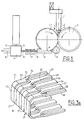
- Figure 1 shows an extruder for thermoplastic 1 which successively presents an extrusion head 1 'to provide a bead or a preform 2 of molten material whose temperature, and therefore viscosity, are chosen to allow it to be calendered between a female roller 3 and a male roller 4.
- the device also has a bead for retaining the bead or preform 2 calendered, a shaper () known per se for the calibration of the bead or the preform 2 which has been calendered, a cooling tank 7, and an extruder of cover having an extrusion head 9 which receives at its upstream end the cooled armature 8, and which produces at its downstream end 12 a profile 10 including the frame.
- the extruder 1 produces a flat or cylindrical cord or a preform having a section for example in the form of U, V, S, L or W, and which is made of rigid thermoplastic material.
- plastics whose basic nature allows a natural adhesion with the flexible covering during the production of the profile for example: flexible PVC (covering) on rigid PVC (frame).
- flexible PVC covering
- rigid PVC frame
- thermoplastic cord is placed between the two rollers (3 and 4) in synchronous co-rotation. It is thus calendered to obtain the frame for example in the form of U.
- the rollers are preferably of large diameter. A large diameter allows for good calendering and better cooling.
- a "male” roller 4 is hollowed out in the negative shape of the drawing to be obtained, the other "female” roller 3 is smooth, for example U-shaped or engraved and perfectly covers the roller 4 tangentially.
- the engraving of the "male” roller 4 is a specific design. he gives the finished profile properties making it suitable for meeting the specifications loads of the finished product.
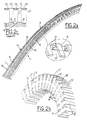
- FIG. 2a An example of a "male" roller 4 constituted by a wheel metallic with a periphery 14 defining a square section torc or rectangular and a relief pattern 15, made for example of metal, is shown in the Figure 2a.
- This wheel enables a bendable U-shaped frame shown in the Figure 2b (after bending). It has a central edge 17 'and bent arms18' which are the counter-impression of the edge 17 and the bent arms 18 of the metal wheel of Figure 2a. located between the arms 16 of the pattern 15 which have one end angled 19.
- the central edge 17 'and the opening 17 "of the arms 18' constitute the dorsal of the frame.
- the drawing is reproduced X times. Machining the engraving of the calendering rollers is obtained by chemical attack, electroerosion, knurling, or milling.
- the solid or fingers 19 of the roller 4 may have inclined edges 21 forming undercuts, so that the solid or fingers 18 'of the frame have re-entrant edges 21 '.
- the construction metal is chosen from pre-treated steels or treated after machining.
- the rollers can be coated with a non-stick coating such as TiN, TiCN or TiAlN, to facilitate the separation of the reinforcement.
- the plastic material still in fusion and of very low viscosity, is crushed between the two rollers 3 and 4. It flows and perfectly fills the engravings hollow, on the other hand it is repelled by the reliefs.
- the particular shape of the solid and openwork designs give its properties to the frame.
- the frame stands out in the appearance of an interrupted chain of two calendering rollers 3 and 4. It is then cooled by calibrating it.
- these sails 19 ' constitute thin bridge regions between the arms 18 '.
- the profile is subsequently produced by extrusion (or co-extrusion) of a covering for example in elastomer or flexible thermoplastic, it occurs after extrusion a withdrawal of material which results in a defect on the finished product more or less pronounced, namely a succession of weak troughs amplitude. but in general perfectly visible, which are located between regions upstream 17 "from the arms 18 ', on the dorsal of the joint.
- the presence of the sails 19' tends to avoid this withdrawal phenomenon, which makes it possible to reduce or even eliminate this phenomenon which has the particularity of interesting the dorsal which is the most visible area of the joint.
- the calendering device can also be constructed in a way different, namely using a pulling machine type called "corrugator” ringed levels.
- N the geometry of the reinforcement to be produced. These can be individually cooled. Machining of N upper forms and N forms interior is carried out according to the same principle as the grille with 2 facing rollers "male Female".
- the tool is more expensive than in the case of rollers, but it produces faster the reinforcement, the effective length of stay of the trapped thermoplastic between the pads being longer. This variant also makes it possible to obtain regions of sailing.
- the following operation, performed at station 9, is an overhead extrusion square to cover the U-shaped frame.
- Various materials can be chosen for perform a function: for example cell TP for waterproofing, appearance skin or color, cosmetic lip, holding lips inside the U.
- the finished profile is cooled without the need for post-forming.
- a preferred variant of the reinforcement covering process is the coextrusion of the bead in 2 TP thermoplastic materials.
- This concept allows to obtain adhesion between the reinforcement and its covering material when there is incompatibility between them.
- the cord made of rigid material is covered of a thin thickness of an intermediate layer in a composition adhering to the recovery.
- This intermediate layer is chosen from extrudable materials compatible with the framework and the posterior covering and able to adhere to them, Grafted EP, acrylic adhesives, or ethylene-vinyl acetate EVA for example.
- Grafted EP acrylic adhesives
- ethylene-vinyl acetate EVA ethylene-vinyl acetate EVA
- Coextruded material with the aim of recyclability, also has the function of being a compatibilizer with the various thermoplastic materials composing the profile.
- the armature can be made with a section that varies over the developed length of a profile.
- automotive can for example allow a good radius taking successively in the 3 dimensions.
- a different thickness in specific places can allow to obtain a modular pinching of the joint (for example in a U shape).
- Dimensions different from the openings can make it possible to obtain a particular radius hold.
- a asymmetry of the axis is also possible.
- the calendering rollers are constructed in a diameter of a developed equal to the length of the profile to be produced or to a multiple or sub-multiple thereof.
- the rollers will have 1.11 meters diameter.
- a marking at the outlet of the die by an ink jet for example, synchronized with the rotation of the grille, identifies the variation sequences of frame section. We can thus cut the piece to a specific length, respecting the required functions.
- the profile shown in Figures 3a and 3b which is likely to be manufactured using the method according to the invention, has a U-shaped section, with solid bars 20 separated by openings 27 of closed contour. Bars solid 20 are extended at their ends by rounding 21 to 90 °, then by branches 22 which separate into two secondary branches 23 and 24 which connect each to one of two adjacent end branches 25 separated by an aperture 26 of open outline. At the secondary branches 23 and 24, the openings 27 and 28 are end with thimble ends 29.
- the additions 27 may have, in the dorsal region of the joint, sails 27 ', similar to sails 19'. As previously, they have only been shown over part of the length of the profile.
- the end branches 25 have re-entrant lateral edges 26 inclined for example by 45 °, which, as already indicated above, facilitates the production and in particular the "demolding" at the outlet of the pebbles and skates.
- the frame 40 shown in Figure 4a is formed of U 42 connected between them by bridge regions 43 located in the branches 42 of the U.
- the frame 40 'shown in Figure 4b is substantially identical to the frame 40 except that the bridge regions 43 'are inclined.
- the frame 50 shown in Figures 5a and 5b has regions central units 51 separated from one another by slots 54 and connected to branches 56 by arm 55.
- the branches 56 are separated from each other by slots 58 which terminate by triangular extensions 58 ′ separating the arms 55.
- Each branch 56 is thus connected by two arms 55 to two adjacent central regions 51.
- seals of Figures 4a, 5a and 5b may also have sail regions (not shown located on their dorsal), and which, as previously come from calendering.
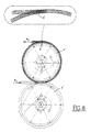
- the frame 60 shown in Figure 6 has an edge longitudinal 61 bordered on one side by fingers 62 and on the other by fingers 66 forming U's (63,64,65).
- the frame thus has an S-profile, with two ridges (67, 68) possibly provided with 67 'and / or 68' sails.
- These reinforcements can be used in particular for making motor vehicle door seals, for example 70 (Figure 7a) or 75 ( Figure 7b) for which their cintrability is used.
- FIG. 8 represents a variant of the device of FIG. 1 in which the extruded bead (or preform) 2 is introduced horizontally in the direction of the arrow F 1 between two rollers 3 'and 4' and after calendering springs tangentially, at point A ', in the direction F 2 opposite to F 1 , after a half-turn on the roller 4.
Landscapes
- Engineering & Computer Science (AREA)
- Mechanical Engineering (AREA)
- Manufacturing & Machinery (AREA)
- Extrusion Moulding Of Plastics Or The Like (AREA)
Abstract
Description
- Le métal des profilés extrudés doit être préformé ou post- formé.
- Le métal s'oxyde dans les extrémités du profilé. Pour l'éviter, une protection est nécessaire. Dans ce cas, on choisit d'utiliser un métal inox ou de déposer du vernis sur les parties exposées à l'oxydation. Cela augmente sensiblement le prix du produit fini.
- Le recyclage du produit fini est rendu très difficile par sa composition multimatériaux de nature différente (métal, caoutchouc, thermoplastique).
- Un coût important du métal manufacturé, ce coût étant encore plus élevé si le métal doit être préparé pour le rendre adhérent au recouvrement en caoutchouc ou thermoplastique TP.
- Une perte de matière duc à la nécessité de réaliser des découpes.
- Le poids de l'armature métallique est élevé, les densités sont de 2,7 pour l'aluminium et de 7,8 pour l'acier.
- La préparation des extrémités est nécessaire pour pouvoir les souder ou les surmouler (dégrafage, ébarbage).
c) un refroidissement du cordon ou de la préforme calandrée.
d) une extrusion d'une couche de recouvrement souple en élastomère ou en matière thermoplastique pour recouvrir l'armature.
- la Figure 1 représente un dispositif pour la mise en oeuvre du procédé selon l'invention ;
- la Figure 2a représente un mode de réalisation d'un galet pour la fabrication d'un profilé représenté à la figure 2b, à l'aide du procédé selon l'invention ; la figure 2c représentant une coupe AA de l'encadré de la figure 2b, avec adjonction d'une illustration "en surélévation" de l'armature ainsi obtenue.
- la Figure 3a représente en perspective une armature correspondant au Brevet Français n° 2 661 972 de la Demanderesse, et la figure 3b la même armature cintrée,
- les Figures 4a, 4h, 5a, 5b et 6 représentent d'autres armatures qui peuvent être réalisées à l'aide du procédé selon l'invention, et
- les Figures 7a et 7b représentent, en coupe, deux exemples de joints de portière de véhicule automobile, comprenant des armatures fabriquées à l'aide du procédé selon l'invention,
- et la Figure 8 représente une variante du dispositif de la figure 1.
Claims (18)
- Procédé de fabrication d'une armature cintrable présentant un motif comportant des pleins et des ajours et destiné à la réalisation d'un profilé d'étanchéité armé, caractérisé en ce qu'il comporte :a) l'extrusion d'un cordon ou d'une préforme en matière thermoplastique,b) un calandrage du cordon ou de la préforme en matière thermoplastique pour lui conférer ledit motif.
- Procédé selon la revendication 1, caractérisé en ce qu'il comporte :
c) un refroidissement du cordon ou de la préforme calandrée. - Procédé selon la revendication 2, caractérisé en ce que ledit refroidissement s'accompagne d'une opération de calibrage.
- Procédé selon une des revendications 1 à 3, caractérisée en ce que l'armature cintrable présente en section la forme d'un U, d'un V, d'un S, d'un L ou d'un W.
- Procédé selon une des revendications 1 à 4, caractérisé en ce que le calandrage est réalisé entre au moins deux galets dont l'un au moins présente une empreinte en creux conformément au dit motif, et qui sont entraínés en rotation simultanée.
- Procédé selon la revendication 5, caractérisé en ce qu'au moins une des galets est refroidi intérieurement.
- Procédé selon une des revendications 1 à 4, caractérisé en ce que le calandrage est réalisé à l'aide d'une chenille de tirage présentant un nombre N de paires de formes présentant des empreintes conformément audit motif.
- Procédé selon une des revendications 5 à 7, caractérisé en ce que les galets ou la chenille de tirage présentent une longueur développée égale ou multiple de la longueur d'un profilé à réaliser, ou bien à un multiple ou à un sous-multiple de celle-ci.
- Procédé selon la revendication 8, caractérisé en ce que les empreintes des galets ou des formes présentent des variations en fonction de l'abscisse x, x variant entre 0 et 1., pour faire varier la section et donc au moins une propriété de l'armature en fonction de ladite abscisse.
- Procédé selon une des revendications précédentes, caractérisé en ce que l'armature présente des branches d'extrémité comportant des bords latéraux inclinés de manière à former des dépouilles.
- Procédé selon une des revendications précédentes, caractérisé en ce que, pour la réalisation d'un profilé d'étanchéité armé, il comporte : d) une extrusion d'une couche de recouvrement souple en élastomère ou en un matériau thermoplastique pour recouvrir l'armature.
- Procédé selon la revendication 11, caractérisé en ce que le matériau de l'armature rigide et le matériau de la couche de recouvrement souple sont choisis parmi : (PVC rigide et PVC souple) ; (PP et PP-EPDM ou SEBS) ; (ABS et SEBS) ; (PVC-ABS et PVC souple) ; (PPMA et SEBS).
- Procédé selon une des revendications 1 ou 12, caractérisé en ce qu'il met en oeuvre une co-extrusion d'une couche intermédiaire et de la couche de matériau de recouvrement, la couche intermédiaire étant en un matériau apte à adhérer au matériau de l'armature et au matériau de recouvrement souple entre lesquelles elle est interposée.
- Procédé selon la revendication 13, caractérisé en ce que la couche intermédiaire est choisie parmi des copolymères Ethylène-Acétate de vinyle EVA ou bien des copolymères Éthylène-Ester acrylique EMA EBA.
- Procédé selon la revendication 13, caractérisé en ce que l'armature est en polyamide PA, la couche intermédiaire est en EP greffé anhydride maléique, et en ce que la couche de recouvrement souple est en EPDM.
- Armature cintrable présentant un motif comportant des pleins et des ajours au moins dans au moins une région de dorsale, caractérisé en ce que les ajours de la région de dorsale présentent des régions de voile de faible épaisseur par rapport aux pleins et qui forment des ponts entre les pleins de la régions dorsale.
- Armature selon la revendication 16, caractérisé en ce que les pleins du motifs de l'armature présentent, en dehors de la région de dorsale, des branches comportant des bords rentrants.
- Profilé caractérisé en ce qu'il comporte une armature cintrable selon la revendication 16 ou 17, ainsi qu'un recouvrement extrudé.
Applications Claiming Priority (2)
| Application Number | Priority Date | Filing Date | Title |
|---|---|---|---|
| FR9913201 | 1999-10-22 | ||
| FR9913201A FR2800005B1 (fr) | 1999-10-22 | 1999-10-22 | Procede de fabrication d'une armature cintrable |
Publications (2)
| Publication Number | Publication Date |
|---|---|
| EP1093902A1 true EP1093902A1 (fr) | 2001-04-25 |
| EP1093902B1 EP1093902B1 (fr) | 2004-02-11 |
Family
ID=9551234
Family Applications (1)
| Application Number | Title | Priority Date | Filing Date |
|---|---|---|---|
| EP00402833A Expired - Lifetime EP1093902B1 (fr) | 1999-10-22 | 2000-10-13 | Procédé de fabrication d'une armature cintrable, armature cintrable telle qu'obtenue par le procédé, et profilé comportant une telle armature |
Country Status (4)
| Country | Link |
|---|---|
| US (1) | US6742255B1 (fr) |
| EP (1) | EP1093902B1 (fr) |
| DE (1) | DE60008183T2 (fr) |
| FR (1) | FR2800005B1 (fr) |
Cited By (6)
| Publication number | Priority date | Publication date | Assignee | Title |
|---|---|---|---|---|
| EP1138461A2 (fr) * | 2000-03-28 | 2001-10-04 | Kinugawa Rubber Industrial Co., Ltd., | Cylindre de gaufrage pour moulage par extrusion |
| EP2126263A1 (fr) * | 2007-02-21 | 2009-12-02 | Cooper-Standard Automotive Inc. | Produit extrudé composé de couches multi-matières |
| WO2010008355A2 (fr) * | 2008-07-12 | 2010-01-21 | K.E.T Kaucuk Ekstruzyon Teknolojisi Sanayi Tic. Ltd. Sti. | Nouveau système de production de joints d’étanchéité |
| WO2011145079A1 (fr) * | 2010-05-20 | 2011-11-24 | Hutchinson | Armature thermoplastique pour profilé d'étanchéité ou d'enjoliveur de véhicule automobile, son procédé de fabrication et ce profilé l'incorporant |
| WO2011145082A1 (fr) * | 2010-05-20 | 2011-11-24 | Hutchinson | Armature thermoplastique pour profilé d'étanchéité ou d'enjoliveur de véhicule automobile, profile l'incorporant et procédé de fabrication d'armatures. |
| EP2868827B1 (fr) * | 2013-10-31 | 2017-05-10 | Welser Profile Austria GmbH | Rail profilé |
Families Citing this family (8)
| Publication number | Priority date | Publication date | Assignee | Title |
|---|---|---|---|---|
| US7467495B2 (en) * | 2002-09-03 | 2008-12-23 | Troester Gmbh And Co. Kg | Vehicle seal with discontinuous alterating soft and rigid u-shaped segments and method of forming same |
| WO2006100628A1 (fr) * | 2005-03-22 | 2006-09-28 | Straub Werke Ag | Element d'ancrage destine a des couplages de tubes |
| DE102007050523A1 (de) | 2007-10-19 | 2009-04-23 | SaarGummi technologies S.à.r.l. | Verfahren zur Herstellung einer Einlage, insbesondere Verstärkungseinlage, für einen Dichtungsstrang |
| CN101952631B (zh) * | 2008-02-28 | 2012-12-05 | 瑞士斯特劳勃管道接头有限公司 | 用于管接头的锚定元件 |
| DE102009010014A1 (de) * | 2009-02-21 | 2010-08-26 | Henniges Automotive Gmbh & Co. Kg | Glasscheibe für ein Autofenster |
| US8205390B2 (en) * | 2009-02-26 | 2012-06-26 | Henniges Automotive Sealing Systems North America, Inc. | Mechanically stiffened weatherseal carrier |
| ITPD20100299A1 (it) * | 2010-10-08 | 2012-04-09 | Impresa Prevedello Isidoro S R L | Pannello fono-assorbente modulare e procedimento per la sua realizzazione |
| CN108192514B (zh) * | 2017-12-28 | 2021-07-06 | 山东兴辰控股有限公司 | 一种热塑性弹性体止水带及其制备方法 |
Citations (4)
| Publication number | Priority date | Publication date | Assignee | Title |
|---|---|---|---|---|
| US3825459A (en) * | 1969-08-15 | 1974-07-23 | A Taylor | Method of making flexible molding strip |
| US4676856A (en) * | 1985-03-18 | 1987-06-30 | Toyoda Gosei Co., Ltd. | Weather strip for vehicle and producing method thereof |
| DE3835211A1 (de) * | 1988-10-15 | 1990-04-26 | Henniges Gummi | Dichtstreifen |
| DE9014184U1 (fr) * | 1990-10-12 | 1990-12-20 | Hutchinson Gummiwarenfabrik Gmbh, 6800 Mannheim, De |
Family Cites Families (9)
| Publication number | Priority date | Publication date | Assignee | Title |
|---|---|---|---|---|
| US3445915A (en) * | 1966-10-21 | 1969-05-27 | Scovill Manufacturing Co | Method of producing folded thermoplastic strips for sliding clasp fasteners |
| IT1157134B (it) * | 1982-12-10 | 1987-02-11 | Saiag Spa | Procedimento ed apparecchiatura per realizzare mediante estrusione continua un trafilato in particolare una guarnizione di tenuta per carrozzerie di autoveicoli presentante successivi tratti di lunghezze predeterminate aventi ciascuno una rispettiva sezione prestabilita e trafilato ottenuto con tale procedimento |
| JPS60142805A (ja) * | 1983-12-29 | 1985-07-29 | ワイケイケイ株式会社 | スライドフアスナ−用フアスナ−エレメントの製造方法並びに製造装置 |
| US4656086A (en) * | 1986-07-21 | 1987-04-07 | United Technologies Automotive, Inc. | Cloth covered pinch welt and method for making same |
| JPS63141849A (ja) * | 1986-12-01 | 1988-06-14 | Hashimoto Forming Co Ltd | モ−ルデイングおよびその製造方法 |
| US4830898A (en) * | 1987-12-16 | 1989-05-16 | Sterling Engineered Products Inc. | Extruded vinyl molding incorporating a stiffener |
| GB8827180D0 (en) * | 1988-11-21 | 1988-12-29 | Schlegel Uk Holdings | Composite extrusion |
| US5489461A (en) * | 1990-11-22 | 1996-02-06 | Toyoda Gosei Co., Ltd. | Rubber layered structure and manufacturing process therefor |
| US5741573A (en) * | 1996-03-06 | 1998-04-21 | The Standard Products Company | Recyclable pinch flange welt and method of making same |
-
1999
- 1999-10-22 FR FR9913201A patent/FR2800005B1/fr not_active Expired - Fee Related
-
2000
- 2000-10-13 DE DE60008183T patent/DE60008183T2/de not_active Expired - Lifetime
- 2000-10-13 EP EP00402833A patent/EP1093902B1/fr not_active Expired - Lifetime
- 2000-10-16 US US09/688,599 patent/US6742255B1/en not_active Expired - Lifetime
Patent Citations (4)
| Publication number | Priority date | Publication date | Assignee | Title |
|---|---|---|---|---|
| US3825459A (en) * | 1969-08-15 | 1974-07-23 | A Taylor | Method of making flexible molding strip |
| US4676856A (en) * | 1985-03-18 | 1987-06-30 | Toyoda Gosei Co., Ltd. | Weather strip for vehicle and producing method thereof |
| DE3835211A1 (de) * | 1988-10-15 | 1990-04-26 | Henniges Gummi | Dichtstreifen |
| DE9014184U1 (fr) * | 1990-10-12 | 1990-12-20 | Hutchinson Gummiwarenfabrik Gmbh, 6800 Mannheim, De |
Cited By (12)
| Publication number | Priority date | Publication date | Assignee | Title |
|---|---|---|---|---|
| EP1138461A2 (fr) * | 2000-03-28 | 2001-10-04 | Kinugawa Rubber Industrial Co., Ltd., | Cylindre de gaufrage pour moulage par extrusion |
| EP1138461A3 (fr) * | 2000-03-28 | 2003-08-27 | Kinugawa Rubber Industrial Co., Ltd., | Cylindre de gaufrage pour moulage par extrusion |
| EP2126263A1 (fr) * | 2007-02-21 | 2009-12-02 | Cooper-Standard Automotive Inc. | Produit extrudé composé de couches multi-matières |
| EP2126263A4 (fr) * | 2007-02-21 | 2012-06-20 | Cooper Standard Automotive Inc | Produit extrudé composé de couches multi-matières |
| WO2010008355A2 (fr) * | 2008-07-12 | 2010-01-21 | K.E.T Kaucuk Ekstruzyon Teknolojisi Sanayi Tic. Ltd. Sti. | Nouveau système de production de joints d’étanchéité |
| WO2010008355A3 (fr) * | 2008-07-12 | 2010-09-02 | K.E.T Kaucuk Ekstruzyon Teknolojisi Sanayi Tic. Ltd. Sti. | Nouveau système de production de joints d’étanchéité |
| WO2011145079A1 (fr) * | 2010-05-20 | 2011-11-24 | Hutchinson | Armature thermoplastique pour profilé d'étanchéité ou d'enjoliveur de véhicule automobile, son procédé de fabrication et ce profilé l'incorporant |
| WO2011145082A1 (fr) * | 2010-05-20 | 2011-11-24 | Hutchinson | Armature thermoplastique pour profilé d'étanchéité ou d'enjoliveur de véhicule automobile, profile l'incorporant et procédé de fabrication d'armatures. |
| FR2960188A1 (fr) * | 2010-05-20 | 2011-11-25 | Hutchinson | Armature thermoplastique pour profile d'etancheite ou d'enjoliveur de vehicule automobile, profile l'incorporant et procede de fabrication d'armatures |
| FR2960189A1 (fr) * | 2010-05-20 | 2011-11-25 | Hutchinson | Armature thermoplastique pour profile d'etancheite ou d'enjoliveur de vehicule automobile, son procede de fabrication et ce profile l'incorporant |
| US8769877B2 (en) | 2010-05-20 | 2014-07-08 | Hutchinson | Thermoplastic frame for a sealing or wheel cover profiled element of a motor vehicle, production method thereof, and profiled element comprising same |
| EP2868827B1 (fr) * | 2013-10-31 | 2017-05-10 | Welser Profile Austria GmbH | Rail profilé |
Also Published As
| Publication number | Publication date |
|---|---|
| FR2800005A1 (fr) | 2001-04-27 |
| EP1093902B1 (fr) | 2004-02-11 |
| FR2800005B1 (fr) | 2002-06-28 |
| US6742255B1 (en) | 2004-06-01 |
| DE60008183T2 (de) | 2004-12-02 |
| DE60008183D1 (de) | 2004-03-18 |
Similar Documents
| Publication | Publication Date | Title |
|---|---|---|
| EP1093902B1 (fr) | Procédé de fabrication d'une armature cintrable, armature cintrable telle qu'obtenue par le procédé, et profilé comportant une telle armature | |
| CA2799745C (fr) | Armature thermoplastique pour profile d'etancheite ou d'enjoliveur de vehicule automobile, profile l'incorporant et procede de fabrication d'armatures | |
| EP2707191A1 (fr) | Profile moule par multi-injection formant un joint d'etancheite ou un enjoliveur pour carrosserie de vehicule automobile, et son procede de fabrication | |
| FR2653377A1 (fr) | Procede et dispositif pour former une bande allongee de decoration en materiau plastique et bande de decoration pour automobile, ainsi obtenue par extrusion. | |
| EP1931842B1 (fr) | Ensemble de profiles | |
| CA2757379C (fr) | Element d'accrochage pour former la partie male d'un auto-agrippant | |
| FR2651171A1 (fr) | Procede et dispositif de fabrication de moulure de cote de caisse de vehicule a partir de matiere thermoplastique extrudee, par refaconnage par compression a chaud dans un moule et bande obtenue. | |
| CA2790128C (fr) | Armature thermoplastique pour profile d'etancheite ou d'enjoliveur de vehicule automobile, son procede de fabrication et ce profile l'incorporant | |
| EP3230101B1 (fr) | Vitrage a joint profile, enjoliveur et noyau et procede de fabrication du vitrage | |
| EP0721856B1 (fr) | Profile d'étanchéité et son procédé de fabrication | |
| FR2561574A1 (fr) | Procede et dispositif de fabrication d'un article composite allonge | |
| EP1122049B1 (fr) | Procédé de fabrication d'une pièce en matière plastique comportant un film décoratif, et pièce ainsi obtenue | |
| FR2845951A1 (fr) | Produit moule par extrusion destine a une automobile et procede de fabrication de ce dernier | |
| EP3619035A1 (fr) | Structure multicouche de tube plastique | |
| FR2621542A1 (fr) | Moulure de garniture pour vehicule, plus particulierement moulure co-extrudee avec un noyau metallique, et son procede de fabrication | |
| JP2006117222A (ja) | 自動車用ガラスモールディング | |
| WO2015092156A1 (fr) | Profile moule par multi-injection formant un joint d'etancheite ou un enjoliveur pour vehicule automobile, procede et moule pour sa fabrication | |
| FR2517010A1 (fr) | Nouvelle armature pour joint d'etancheite, son procede de preparation et ses utilisations | |
| CA3024759A1 (fr) | Vitrage a joint profile et enjoliveur et procede de fabrication du vitrage | |
| FR2887823A1 (fr) | Produit moule par extrusion comportant un materiau central | |
| WO2003011582A2 (fr) | Procede pour la realisation d'un jouet ou d'un article de sport en forme de tore | |
| JP4197060B2 (ja) | 電線カバーの製造方法 | |
| EP0327474B1 (fr) | Barre de seuil et son procédé de réalisation | |
| EP2398716A1 (fr) | Capsule de bouchage ou surbouchage a bande dechirable non blessante et son procede de fabrication | |
| WO2006008254A1 (fr) | Procede de fabrication d'un cordon de soudure |
Legal Events
| Date | Code | Title | Description |
|---|---|---|---|
| PUAI | Public reference made under article 153(3) epc to a published international application that has entered the european phase |
Free format text: ORIGINAL CODE: 0009012 |
|
| AK | Designated contracting states |
Kind code of ref document: A1 Designated state(s): DE FR GB |
|
| AX | Request for extension of the european patent |
Free format text: AL;LT;LV;MK;RO;SI |
|
| 17P | Request for examination filed |
Effective date: 20010911 |
|
| AKX | Designation fees paid |
Free format text: DE FR GB |
|
| 17Q | First examination report despatched |
Effective date: 20020919 |
|
| RTI1 | Title (correction) |
Free format text: METHOD OF MANUFACTURING A BENDABLE CORE, CORE AS OBTAINED BY THE METHOD, AND PROFILE COMPRISING SUCH A CORE |
|
| GRAP | Despatch of communication of intention to grant a patent |
Free format text: ORIGINAL CODE: EPIDOSNIGR1 |
|
| RAP1 | Party data changed (applicant data changed or rights of an application transferred) |
Owner name: HUTCHINSON |
|
| GRAS | Grant fee paid |
Free format text: ORIGINAL CODE: EPIDOSNIGR3 |
|
| GRAA | (expected) grant |
Free format text: ORIGINAL CODE: 0009210 |
|
| AK | Designated contracting states |
Kind code of ref document: B1 Designated state(s): DE FR GB |
|
| PG25 | Lapsed in a contracting state [announced via postgrant information from national office to epo] |
Ref country code: GB Free format text: LAPSE BECAUSE OF FAILURE TO SUBMIT A TRANSLATION OF THE DESCRIPTION OR TO PAY THE FEE WITHIN THE PRESCRIBED TIME-LIMIT Effective date: 20040211 |
|
| REG | Reference to a national code |
Ref country code: GB Ref legal event code: FG4D Free format text: NOT ENGLISH |
|
| REF | Corresponds to: |
Ref document number: 60008183 Country of ref document: DE Date of ref document: 20040318 Kind code of ref document: P |
|
| GBV | Gb: ep patent (uk) treated as always having been void in accordance with gb section 77(7)/1977 [no translation filed] |
Effective date: 20040211 |
|
| PLBE | No opposition filed within time limit |
Free format text: ORIGINAL CODE: 0009261 |
|
| STAA | Information on the status of an ep patent application or granted ep patent |
Free format text: STATUS: NO OPPOSITION FILED WITHIN TIME LIMIT |
|
| 26N | No opposition filed |
Effective date: 20041112 |
|
| REG | Reference to a national code |
Ref country code: FR Ref legal event code: PLFP Year of fee payment: 16 |
|
| REG | Reference to a national code |
Ref country code: FR Ref legal event code: PLFP Year of fee payment: 17 |
|
| REG | Reference to a national code |
Ref country code: FR Ref legal event code: PLFP Year of fee payment: 18 |
|
| REG | Reference to a national code |
Ref country code: FR Ref legal event code: PLFP Year of fee payment: 19 |
|
| PGFP | Annual fee paid to national office [announced via postgrant information from national office to epo] |
Ref country code: FR Payment date: 20180925 Year of fee payment: 19 |
|
| PGFP | Annual fee paid to national office [announced via postgrant information from national office to epo] |
Ref country code: DE Payment date: 20181019 Year of fee payment: 19 |
|
| REG | Reference to a national code |
Ref country code: DE Ref legal event code: R119 Ref document number: 60008183 Country of ref document: DE |
|
| PG25 | Lapsed in a contracting state [announced via postgrant information from national office to epo] |
Ref country code: DE Free format text: LAPSE BECAUSE OF NON-PAYMENT OF DUE FEES Effective date: 20200501 |
|
| PG25 | Lapsed in a contracting state [announced via postgrant information from national office to epo] |
Ref country code: FR Free format text: LAPSE BECAUSE OF NON-PAYMENT OF DUE FEES Effective date: 20191031 |