EP1092841A1 - Ventilschaftabdichtung - Google Patents
Ventilschaftabdichtung Download PDFInfo
- Publication number
- EP1092841A1 EP1092841A1 EP00115709A EP00115709A EP1092841A1 EP 1092841 A1 EP1092841 A1 EP 1092841A1 EP 00115709 A EP00115709 A EP 00115709A EP 00115709 A EP00115709 A EP 00115709A EP 1092841 A1 EP1092841 A1 EP 1092841A1
- Authority
- EP
- European Patent Office
- Prior art keywords
- valve stem
- sealing element
- stem guide
- stiffening ring
- guide
- Prior art date
- Legal status (The legal status is an assumption and is not a legal conclusion. Google has not performed a legal analysis and makes no representation as to the accuracy of the status listed.)
- Ceased
Links
- 238000007789 sealing Methods 0.000 claims abstract description 52
- 229920001971 elastomer Polymers 0.000 claims abstract description 9
- 239000000806 elastomer Substances 0.000 claims abstract description 9
- 239000000463 material Substances 0.000 claims abstract description 9
- 230000007704 transition Effects 0.000 claims abstract description 3
- 238000002485 combustion reaction Methods 0.000 claims description 2
- 239000013536 elastomeric material Substances 0.000 claims 1
- 230000002787 reinforcement Effects 0.000 abstract 2
- 210000002414 leg Anatomy 0.000 description 9
- 238000003754 machining Methods 0.000 description 2
- 238000004519 manufacturing process Methods 0.000 description 2
- 239000011324 bead Substances 0.000 description 1
- 230000015572 biosynthetic process Effects 0.000 description 1
- 210000003746 feather Anatomy 0.000 description 1
- 238000003780 insertion Methods 0.000 description 1
- 230000037431 insertion Effects 0.000 description 1
- 238000005461 lubrication Methods 0.000 description 1
- 239000002923 metal particle Substances 0.000 description 1
- 230000003068 static effect Effects 0.000 description 1
- 210000000689 upper leg Anatomy 0.000 description 1
- 238000004073 vulcanization Methods 0.000 description 1
Images

Classifications
-
- F—MECHANICAL ENGINEERING; LIGHTING; HEATING; WEAPONS; BLASTING
- F01—MACHINES OR ENGINES IN GENERAL; ENGINE PLANTS IN GENERAL; STEAM ENGINES
- F01L—CYCLICALLY OPERATING VALVES FOR MACHINES OR ENGINES
- F01L3/00—Lift-valve, i.e. cut-off apparatus with closure members having at least a component of their opening and closing motion perpendicular to the closing faces; Parts or accessories thereof
- F01L3/08—Valves guides; Sealing of valve stem, e.g. sealing by lubricant
Definitions
- valve stems Different designs are used to seal valve stems known.
- the seal is to prevent oil from Valve seat arrives, but on the other hand the valve stem with sufficient oil for to supply the lubrication so that there is no excessive wear on the Valve stem and on the valve stem guide occurs.
- FIG. 170 An embodiment for the attachment of a sealing element on the Valve stem guide is shown in DE OS 197 09 170.
- the sealing element is also there a sealing lip provided by a coil spring to the Valve stem is pressed.
- the sealing element is on the valve stem guide put on and surrounded by a stiffening ring.
- the valve stem guide is provided with a paragraph on which the attached sealing element with Stiffening ring comes to rest. This paragraph thus makes the situation of the sealing element on the valve stem guide.
- the sealing element has just a sealing function.
- sealing element shows the EP-OS 0 645 524.
- the valve spring rests on the flange of one metallic stiffening ring.
- the sealing element thus has the function of Sealing and the support for the valve spring.
- the invention is based on the above prior art. You have the task to create a valve stem seal that is as simple as possible their structure, takes up little space and is simple Manufacturing allowed.
- the seal is also intended to have a simple design the valve stem guide and the valve stem guide should be on Minimum dimensions in the outer diameter can be reduced.
- the sealing element should be attachable to the valve stem guide in a clearly defined manner. In addition, should a change from the valve stem seal without valve spring support to one Version with valve spring support without changing the valve stem guide, to be possible.
- valve stem seal Internal combustion engines for vehicles with on the valve stem guide attached and positioned elastomeric sealing element with am Valve stem of the spring-loaded sealing lip and one that Stiffening ring enclosing sealing element according to the invention achieved that the positioning of the sealing element on the end face of the The valve stem is guided.
- the sealing element is no longer through the lower edge of the stiffening body and a paragraph on the Valve stem guide positioned, but by a radial ring surface below the dynamic seal and the top (end face) of the Valve stem guide.
- special paragraphs fall on the Valve stem guide away.
- the valve stem guide can be omitted the positioning shoulders are dimensioned so that their outer diameter is reduced to the smallest possible size, whereby a Material savings in valve stem guide is achieved.
- valve stem guide from a tube with the same inside and Outside diameter can be made over its entire length. Any machining operations on the outside diameter of the valve stem guide after their insertion in the cylinder head, this is no longer necessary. This is for one associated with simplified manufacturing and the other is Reduced possibility that metal particles remain in the cylinder head, which at Commissioning can lead to damage. A faulty one Machining the valve stem guide outside leads to eccentricity and may require reworking of the entire cylinder head.
- the stiffening ring is seen in longitudinal section as an angle or as an S-shape formed, with the inward leg at the transition to Sealing lip is in the area of the dynamic sealing element and from Elastomer material of the sealing element is included.
- This training of Leg in connection with the elastomer material of the sealing element results a good mounting of the sealing lip on the valve stem.
- the one facing outwards Leg can serve as a stop surface for an assembly tool.
- the stiffening ring is with the entire length of its inner surface Elastomer material of the sealing element connected.
- the Stiffening ring is therefore the axially aligned part of the Angle on its inner surface covered with the elastomer material.
- the stiffening ring is designed in an S shape, it can face outwards directed legs also as a valve spring support in the form of a Feather retaining collar can be formed.
- the thigh correspondingly large, with a correspondingly large diameter to design.
- the spring retaining collar rests on the cylinder head.
- a particular advantage of the invention is that of the variant of Valve stem seal without spring retaining collar for the variant with spring retaining collar can be changed without changing the valve stem guide have to.
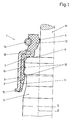
- the valve stem seal 1 shown in section in FIG. 1 consists of essentially from the elastomeric sealing element 2 with the stiffening ring 3 and the spring-loaded sealing lip 4.
- the sealing element 2 is on the Valve stem guide 5 attached. His inward leg 12 lies on the end face 6 of the valve stem guide 5.
- the valve stem guide 5 is used in a conventional manner in the cylinder head of an engine block. It comprises the valve stem 9, which is displaceable in the longitudinal direction.
- the sealing element 2 is placed on the valve stem guide 5. To one To achieve a static seal, the sealing element 2 with the ring beads 10 provided. The slope 11 serves to guide the sealing element in the Assembly. The sealing element 2 is all around the stiffening ring 3 bordered. The stiffening ring 3 is with the leg directed inwards 12 provided, which comprises of the elastomer material 13 of the sealing element 2 is. The sealing lip 4 sealingly includes the valve stem 9. It is with the annular coil spring 14 spanned. The sealing element 2 has the axial Annular surface 7 with which it rests on the end face 6 of the valve stem guide 5. As a result, the unique positioning of the sealing element 2 on the Valve stem guide 5 reached.
- the stiffening ring 3 is also with the outward leg 15 provided as a stop surface for a appropriate assembly tool is used.
- the between the legs 12 and 15 in the longitudinal direction of the valve stem guide 5 part of the Stiffening ring 3 is over the entire length of its inner surface 16 with the Elastomer material 13 of the sealing element 2 connected by vulcanization.
- FIG. 2 shows an embodiment of the valve stem seal 1, in which the outward leg 15 of the stiffening ring 3 with is also provided an S-shaped projection 17, which serves as a valve spring support for the indicated valve spring 18.
- the Valve spring support 19 bears against the cylinder head 8.
- valve stem guide is on by a tube its entire length has the same inside diameter d and outside diameter D formed. Paragraphs or similar embodiments for holding the Sealing elements in the specified position are not required.
Landscapes
- Engineering & Computer Science (AREA)
- Mechanical Engineering (AREA)
- General Engineering & Computer Science (AREA)
- Sealing With Elastic Sealing Lips (AREA)
Abstract
Ventilschaftabdichtung an Verbrennungskraftmaschinen für Fahrzeuge mit auf die Ventilschaftführung aufgesetzten und daran positionierten elastomerem Dichtelement mit am Ventilschaft anliegender federbelasteter Dichtlippe und einem das Dichtelement einfassenden Versteifungsring, wobei die Positionierung des Dichtelements (2) an der Stirnfläche (6) der Ventilschaftführung (5) erfolgt. <IMAGE>
Description
Zur Abdichtung von Ventilschäften sind unterschiedliche Konstruktionen
bekannt geworden. Die Abdichtung soll zum einen verhindern, daß Öl zum
Ventilsitz gelangt, zum anderen aber den Ventilschaft mit ausreichend Öl für
die Schmierung zu versorgen, damit kein all zu hoher Verschleiß am
Ventilschaft und an der Ventilschaftführung auftritt.
Ein Ausführungsbeispiel für die Anbringung eines Dichtelements an der
Ventilschaftführung zeigt die DE OS 197 09 170. Dort ist das Dichtelement mit
einer Dichtlippe versehen, die von einer Schraubenzugfeder an den
Ventilschaft gedrückt wird. Das Dichtelement ist auf die Ventilschaftführung
aufgesetzt und von einem Versteifungsring umgeben. Die Ventilschaftführung
ist mit einem Absatz versehen, an dem das aufgesetzte Dichtelement mit
Versteifungsring zur Anlage kommt. Durch diesen Absatz wird somit die Lage
des Dichtelements an der Ventilschaftführung bestimmt. Das Dichtelement hat
lediglich eine Dichtfunktion.
Eine andere Möglichkeit für die Anordnung eines Dichtelements zeigt die EP-OS
0 645 524. Dort stützt sich die Ventilfeder auf dem Flansch eines
metallischen Versteifungsrings ab. Das Dichtelement hat somit die Funktion der
Abdichtung und der Abstützung für die Ventilfeder.
Die Erfindung geht von obigem Stand der Technik aus. Ihr liegt die Aufgabe
zugrunde, eine Ventilschaftabdichtung zu schaffen, die möglichst einfach in
ihrem Aufbau ist, einen geringen Bauraum einnimmt und eine einfache
Herstellung erlaubt. Die Dichtung soll außerdem eine einfache Ausgestaltung
der Ventilschaftführung ergeben und die Ventilschaftführung soll auf ein
Mindestmaß im Außendurchmesser reduziert werden. Das Dichtelement soll
eindeutig definiert an der Ventilschaftführung befestigbar sein. Außerdem soll
ein Wechsel von der Ventilschaftabdichtung ohne Ventilfederauflage in eine
Version mit Ventilfederauflage ohne die Ventilschaftführung zu verändern,
möglich sein.
Die Lösung der gestellten Aufgabe wird bei einer Ventilschaftabdichtung an
Verbrennungskraftmaschinen für Fahrzeuge mit auf die Ventilschaftführung
aufgesetzten und daran positionierten elastomeren Dichtelement mit am
Ventilschaft anliegender federbelasteter Dichtlippe und einem das
Dichtelement einfassenden Versteifungsring erfindungsgemäß dadurch
erreicht, daß die Positionierung des Dichtelements an der Stirnfläche der
Ventilschaftführung erfolgt. Bei der erfindungsgemäßen Ausführungsform wird
folglich die an sich bewährte Ausbildung des Dichtelements mit einer
federbelasteten Dichtlippe und einem das Dichtelement einfassenden
Versteifungsring beibehalten. Das Dichtelement wird jedoch nicht mehr durch
die untere Kante des Versteifungskörpers und einen Absatz an der
Ventilschaftführung positioniert, sondern durch eine radiale Ringfläche
unterhalb der dynamischen Dichtung und der Oberseite (Stirnfläche) der
Ventilschaftführung. Dadurch fallen besondere Absätze an der
Ventilschaftführung weg. Außerdem kann die Ventilschaftführung bei Wegfall
der Positionierungsabsätze so bemessen werden, daß ihr Außendurchmesser
auf eine geringstmögliche Größe reduziert wird, wodurch eine
Materialeinsparung bei der Ventilschaftführung erreicht wird.
Die Ausbildung des Dichtelements mit Versteifungsring und seiner
Positionierung an der Stirnfläche der Ventilschaftführung ermöglicht, daß die
Ventilschaftführung aus einem Rohr mit gleichem Innen- und
Außendurchmesser auf seiner gesamten Länge hergestellt werden kann.
Eventuelle Bearbeitungsgänge am Außendurchmesser der Ventilschaftführung
nach ihrer Einfügung in den Zylinderkopf entfallen hierdurch. Dies ist zum
einen mit vereinfachter Fertigung verbunden und zum anderen ist die
Möglichkeit reduziert, daß Metallpartikel im Zylinderkopf zurückbleiben, die bei
Inbetriebnahme zu Beschädigungen führen können. Ein fehlerhaftes
Bearbeiten der Ventilschaftführungsaußenseite führt zur Exzentrizität und
erfordert gegebenenfalls ein Nacharbeiten des gesamten Zylinderkopfes.
Der Versteifungsring wird im Längsschnitt gesehen als Winkel oder als S-Form
ausgebildet, wobei der nach innen gerichtete Schenkel am Übergang zur
Dichtlippe im Bereich des dynamischen Dichtelements liegt und vom
Elastomermaterial des Dichtelements umfaßt ist. Diese Ausbildung des
Schenkels in Verbindung mit dem Elastomermaterial des Dichtelements ergibt
eine gute Halterung der Dichtlippe am Ventilschaft. Der nach außen gerichtete
Schenkel kann als Anschlagfläche für ein Montagewerkzeug dienen.
Der Versteifungsring ist über die gesamte Länge seiner Innenfläche mit dem
Elastomermaterial des Dichtelements verbunden. Bei einer Ausbildung des
Versteifungsrings als Winkel ist folglich der axial ausgerichtete Teil des
Winkels auf seiner Innenfläche mit dem Elastomermaterial überzogen.
Bei einer Ausbildung des Versteifungsrings in S-Form kann der nach außen
gerichtete Schenkel auch als Ventilfederauflage in Form eines
Federhaltebunds ausgebildet sein. In diesem Fall ist der Schenkel
entsprechend groß, mit einem entsprechend großen Durchmesser
auszugestalten. Der Federhaltebund liegt auf dem Zylinderkopf auf.
Ein besonderer Vorteil der Erfindung liegt darin, daß von der Variante der
Ventilschaftdichtung ohne Federhaltebund zu der Variante mit Federhaltebund
gewechselt werden kann, ohne dabei die Ventilschaftführung verändern zu
müssen.
Anhand der in der Zeichnung dargestellten Ausführungsbeispiele wird die
Erfindung näher erläutert
Es zeigt:
- Figur 1
- eine Anordnung der Ventilschaftabdichtung im Schnitt eingesetzt in den Zylinderkopf und
- Figur 2
- eine Ventilschaftabdichtung im Schnitt mit einer Ventilfederauflage
Die in der Figur 1 im Schnitt gezeigte Ventilschaftabdichtung 1 besteht im
wesentlichen aus dem elastomeren Dichtelement 2 mit dem Versteifungsring 3
und der federbelasteten Dichtlippe 4. Das Dichtelement 2 ist auf die
Ventilschaftführung 5 aufgesetzt. Sein nach innen gerichteter Schenkel 12 liegt
an der Stirnfläche 6 der Ventilschaftführung 5 an. Die Ventilschaftführung 5 ist
in an sich bekannter Weise in den Zylinderkopf eines Motorblocks eingesetzt.
Sie umfaßt den Ventilschaft 9, der in Längsrichtung verschiebbar ist.
Das Dichtelement 2 ist auf die Ventilschaftführung 5 aufgesetzt. Um einen
statischen Dichtsitz zu erreichen, ist das Dichtelement 2 mit den Ringwülsten
10 versehen. Die Schräge 11 dient zur Führung des Dichtelements bei der
Montage. Das Dichtelement 2 ist von dem Versteifungsring 3 rundum
eingefaßt. Der Versteifungsring 3 ist mit dem nach innen gerichteten Schenkel
12 versehen, der von dem Elastomermaterial 13 des Dichtelements 2 umfaßt
ist. Die Dichtlippe 4 umfaßt dichtend den Ventilschaft 9. Sie ist mit der
ringförmigen Schraubenfeder 14 umspannt. Das Dichtelement 2 hat die axiale
Ringfläche 7 mit der es an der Stirnfläche 6 der Ventilschaftführung 5 anliegt.
Dadurch wird die eindeutige Positionierung des Dichtelements 2 auf der
Ventilschaftführung 5 erreicht. Der Versteifungsring 3 ist außerdem mit dem
nach außen gerichteten Schenkel 15 versehen, der als Anschlagfläche für ein
entsprechendes Montagewerkzeug dient. Der zwischen den Schenkeln 12 und
15 in Längsrichtung der Ventilschaftführung 5 liegende Teil des
Versteifungsring 3 ist über die gesamte Länge seiner Innenfläche 16 mit dem
Elastomermaterial 13 des Dichtelements 2 durch Vulkanisation verbunden.
In der Figur 2 ist eine Ausführungsform der Ventilschaftabdichtung 1 gezeigt,
bei der der nach außen gerichtete Schenkel 15 des Versteifungsrings 3 mit
einem ebenfalls s-förmig im Schnitt ausgebildeten Ansatz 17 versehen ist, der
als Ventilfederauflage für die angedeutete Ventilfeder 18 dient. Die
Ventilfederauflage 19 liegt am Zylinderkopf 8 an.
In allen Ausführungsformen ist die Ventilschaftführung durch ein Rohr mit auf
seiner gesamten Länge gleichem Innendurchmesser d und Außendurchmesser
D gebildet. Absätze oder ähnliche Ausführungsformen zur Halterung des
Dichtelements in der vorgegebenen Position sind nicht erforderlich.
Claims (6)
- Ventilschaftabdichtung an Verbrennungskraftmaschinen für Fahrzeuge mit auf die Ventilschaftführung aufgesetzten und daran positionierten elastomerem Dichtelement mit am Ventilschaft anliegender federbelasteter Dichtlippe und einem das Dichtelement einfassenden Versteifungsring, dadurch gekennzeichnet, daß die Positionierung des Dichtelements (2) an der Stirnfläche (6) der Ventilschaftführung (5) erfolgt.
- Ventilschaftabdichtung nach Anspruch 1, dadurch gekennzeichnet, daß das Dichtelement (2) mit einer axialen Ringfläche (7) für die Anlage an der Stirnfläche (6) der Ventilschaftführung (5) versehen ist.
- Ventilschaftabdichtung nach Anspruch 1 oder 2, dadurch gekennzeichnet, daß der Versteifungsring (3) im Längsschnitt gesehen eine Winkel- oder S-Form hat, wobei der nach innen gerichtete Schenkel (12) am Übergang zur Dichtlippe (4) liegt und vom Elastomermaterial (13) des Dichtelements (2) umfaßt ist.
- Ventilschaftabdichtung nach einem der Ansprüche 1 bis 3, dadurch gekennzeichnet, daß der in Längsrichtung der Ventilschaftführung (5) liegende Teil des Versteifungsrings (3) über die gesamte Länge seiner Innenfläche (16) mit dem Elastomermaterial (13) des Dichtelements (2) verbunden ist.
- Ventilschaftabdichtung nach einem der Ansprüche 1 bis 4, dadurch gekennzeichnet, daß der nach außen gerichtete Schenkel (15) der S-Form als Montageauflage oder als Ventilfederauflage (19) ausgebildet ist.
- Ventilschaftabdichtung nach einem der Ansprüche 1 bis 5, dadurch gekennzeichnet, daß die Ventilschaftführung (5) aus einem Rohr mit auf seiner gesamten Länge konstanten innen- und Außendurchmesser (d, D) besteht.
Applications Claiming Priority (2)
| Application Number | Priority Date | Filing Date | Title |
|---|---|---|---|
| DE19949248 | 1999-10-13 | ||
| DE1999149248 DE19949248A1 (de) | 1999-10-13 | 1999-10-13 | Ventilschaftabdichtung |
Publications (1)
| Publication Number | Publication Date |
|---|---|
| EP1092841A1 true EP1092841A1 (de) | 2001-04-18 |
Family
ID=7925428
Family Applications (1)
| Application Number | Title | Priority Date | Filing Date |
|---|---|---|---|
| EP00115709A Ceased EP1092841A1 (de) | 1999-10-13 | 2000-07-21 | Ventilschaftabdichtung |
Country Status (2)
| Country | Link |
|---|---|
| EP (1) | EP1092841A1 (de) |
| DE (1) | DE19949248A1 (de) |
Cited By (2)
| Publication number | Priority date | Publication date | Assignee | Title |
|---|---|---|---|---|
| EP1854965A1 (de) * | 2006-05-02 | 2007-11-14 | Carl Freudenberg KG | Öldichtung |
| EP1857645A3 (de) * | 2006-05-19 | 2009-12-16 | Carl Freudenberg KG | Ventilschaftsiegel |
Families Citing this family (2)
| Publication number | Priority date | Publication date | Assignee | Title |
|---|---|---|---|---|
| DE10207818B4 (de) * | 2002-02-25 | 2006-04-06 | Carl Freudenberg Kg | Ventilschaftabdichtung an Verbrennungskraftmaschinen |
| DE102021102911B4 (de) | 2021-02-09 | 2024-12-19 | Audi Aktiengesellschaft | Ventilschaftdichtung für eine Brennkraftmaschine sowie entsprechende Brennkraftmaschine |
Citations (6)
| Publication number | Priority date | Publication date | Assignee | Title |
|---|---|---|---|---|
| JPS5596316A (en) * | 1979-01-12 | 1980-07-22 | Nok Corp | Valve stem seal |
| US4773363A (en) * | 1987-05-01 | 1988-09-27 | Microdot Inc. | Fixed valve stem oil deflector |
| US4834037A (en) * | 1987-10-14 | 1989-05-30 | Dana Corporation | Unitary molded plastic valve seal |
| EP0645524A1 (de) | 1993-09-28 | 1995-03-29 | Firma Carl Freudenberg | Ventilschaftdichtung zum Aufschieben auf eine im Zylinderkopf einer Verbrennungskraftmaschine gehaltene Ventilschaftführung |
| US5553869A (en) * | 1994-12-12 | 1996-09-10 | Dana Corporation | Bonded valve stem seal with retainer tangs |
| DE19709170A1 (de) | 1997-03-06 | 1998-09-24 | Cr Elastomere Gmbh | Abdichtung für hin- und hergehende Maschinenteile, insbesondere Ventilschaftabdichtung |
Family Cites Families (2)
| Publication number | Priority date | Publication date | Assignee | Title |
|---|---|---|---|---|
| GB1096429A (en) * | 1965-06-25 | 1967-12-29 | Daimler Benz Ag | Improvements relating to sealing arrangements for valve stems of internal combustionengines |
| US5174256A (en) * | 1991-11-25 | 1992-12-29 | Dana Corporation | Variable guide height valve seal |
-
1999
- 1999-10-13 DE DE1999149248 patent/DE19949248A1/de not_active Ceased
-
2000
- 2000-07-21 EP EP00115709A patent/EP1092841A1/de not_active Ceased
Patent Citations (6)
| Publication number | Priority date | Publication date | Assignee | Title |
|---|---|---|---|---|
| JPS5596316A (en) * | 1979-01-12 | 1980-07-22 | Nok Corp | Valve stem seal |
| US4773363A (en) * | 1987-05-01 | 1988-09-27 | Microdot Inc. | Fixed valve stem oil deflector |
| US4834037A (en) * | 1987-10-14 | 1989-05-30 | Dana Corporation | Unitary molded plastic valve seal |
| EP0645524A1 (de) | 1993-09-28 | 1995-03-29 | Firma Carl Freudenberg | Ventilschaftdichtung zum Aufschieben auf eine im Zylinderkopf einer Verbrennungskraftmaschine gehaltene Ventilschaftführung |
| US5553869A (en) * | 1994-12-12 | 1996-09-10 | Dana Corporation | Bonded valve stem seal with retainer tangs |
| DE19709170A1 (de) | 1997-03-06 | 1998-09-24 | Cr Elastomere Gmbh | Abdichtung für hin- und hergehende Maschinenteile, insbesondere Ventilschaftabdichtung |
Non-Patent Citations (1)
| Title |
|---|
| PATENT ABSTRACTS OF JAPAN vol. 004, no. 143 (M - 035) 8 October 1980 (1980-10-08) * |
Cited By (2)
| Publication number | Priority date | Publication date | Assignee | Title |
|---|---|---|---|---|
| EP1854965A1 (de) * | 2006-05-02 | 2007-11-14 | Carl Freudenberg KG | Öldichtung |
| EP1857645A3 (de) * | 2006-05-19 | 2009-12-16 | Carl Freudenberg KG | Ventilschaftsiegel |
Also Published As
| Publication number | Publication date |
|---|---|
| DE19949248A1 (de) | 2001-04-19 |
Similar Documents
| Publication | Publication Date | Title |
|---|---|---|
| EP0561817B1 (de) | Mehrteiliger, gekühlter kolben für verbrennungsmotoren | |
| DE10131075B4 (de) | Aggregatelager in Buchsenform | |
| DE3405780A1 (de) | Fluid-dichtung | |
| EP0485697A2 (de) | Elastisches Gleitlager | |
| DE3333229A1 (de) | Fluiddichtung | |
| DE202005021716U1 (de) | Nockenwelle | |
| DE2634153A1 (de) | Ventil | |
| DE102019212908A1 (de) | Schwingungsdämpfer mit verstellbarer Dämpfkraft | |
| DE102019214905A1 (de) | Luftfederbein mit speziell ausgebildeter Befestigung eines Abrollkolbens am Stoßdämpfer | |
| DE10118229A1 (de) | Hydraulisch dämpfendes Buchsenlager | |
| EP0149079B1 (de) | Elastisches Dreh-Gleitlager | |
| DE102014215000A1 (de) | Einsatz für eine Dichtung eines Wälzlagers, Dichtung mit dem Einsatz, Kreuzgelenk und Lagerbüchse mit der Dichtung | |
| EP1176332A2 (de) | Luftfederbein | |
| DE1575689B1 (de) | Kugelgelenk mit einer dichtungsmanschette | |
| DE102006027500A1 (de) | Axialgleitlagerring | |
| DE19949248A1 (de) | Ventilschaftabdichtung | |
| DE3418804A1 (de) | Schutzmanschette fuer zylindrische teile, insbesondere fuer eine bolzenfuehrung einer teilbelag-scheibenbremse | |
| EP1338762B1 (de) | Ventilschaftabdichtung an Verbrennungskraftmaschinen | |
| DE102013213137A1 (de) | Anordnung einer Schmiermittelspritzdüse | |
| DE10325764B3 (de) | Ventilschaftabdichtung für Brennkraftmaschinen | |
| DE3723714C1 (en) | Air guide housing for a radiator | |
| EP1391619B1 (de) | Kugelgelenk | |
| DE2445518A1 (de) | Halteelement fuer eine dichtung | |
| DE202008007478U1 (de) | Kraftstoff-Injektor, Kraftstoff-Injektor-Sortiment sowie Verbrennungsmotor | |
| DE4038378C2 (de) |
Legal Events
| Date | Code | Title | Description |
|---|---|---|---|
| PUAI | Public reference made under article 153(3) epc to a published international application that has entered the european phase |
Free format text: ORIGINAL CODE: 0009012 |
|
| 17P | Request for examination filed |
Effective date: 20010206 |
|
| AK | Designated contracting states |
Kind code of ref document: A1 Designated state(s): DE FR IT |
|
| AX | Request for extension of the european patent |
Free format text: AL;LT;LV;MK;RO;SI |
|
| AKX | Designation fees paid |
Free format text: DE FR IT |
|
| RAP1 | Party data changed (applicant data changed or rights of an application transferred) |
Owner name: CARL FREUDENBERG KG |
|
| 17Q | First examination report despatched |
Effective date: 20031103 |
|
| STAA | Information on the status of an ep patent application or granted ep patent |
Free format text: STATUS: THE APPLICATION HAS BEEN REFUSED |
|
| 18R | Application refused |
Effective date: 20050211 |