EP1092341A1 - Vorrichtung zur Aufnahme und Halterung einer Schneidwerksbaugruppe am schwenkbaren Schrägförderer eines selbstfahrenden Mähdreschers - Google Patents
Vorrichtung zur Aufnahme und Halterung einer Schneidwerksbaugruppe am schwenkbaren Schrägförderer eines selbstfahrenden Mähdreschers Download PDFInfo
- Publication number
- EP1092341A1 EP1092341A1 EP00120980A EP00120980A EP1092341A1 EP 1092341 A1 EP1092341 A1 EP 1092341A1 EP 00120980 A EP00120980 A EP 00120980A EP 00120980 A EP00120980 A EP 00120980A EP 1092341 A1 EP1092341 A1 EP 1092341A1
- Authority
- EP
- European Patent Office
- Prior art keywords
- receiving
- holding
- cutting
- rear wall
- cutting unit
- Prior art date
- Legal status (The legal status is an assumption and is not a legal conclusion. Google has not performed a legal analysis and makes no representation as to the accuracy of the status listed.)
- Granted
Links
- 238000003306 harvesting Methods 0.000 claims description 5
- 230000003014 reinforcing effect Effects 0.000 claims description 2
- 239000002689 soil Substances 0.000 description 4
- 230000002787 reinforcement Effects 0.000 description 3
- 230000008878 coupling Effects 0.000 description 1
- 238000010168 coupling process Methods 0.000 description 1
- 238000005859 coupling reaction Methods 0.000 description 1
- 230000000087 stabilizing effect Effects 0.000 description 1
Images


Classifications
-
- A—HUMAN NECESSITIES
- A01—AGRICULTURE; FORESTRY; ANIMAL HUSBANDRY; HUNTING; TRAPPING; FISHING
- A01D—HARVESTING; MOWING
- A01D41/00—Combines, i.e. harvesters or mowers combined with threshing devices
- A01D41/12—Details of combines
- A01D41/14—Mowing tables
- A01D41/16—Devices for coupling mowing tables to conveyors
Definitions
- the invention relates to a device for attaching and holding a device for Picking up crop on a swiveling inclined conveyor for forwarding the crop into a harvester, such as a self-propelled combine, with the Device on the housing of the feeder in its front area attached receiving hook for gripping under each receiving hook assigned supporting bolt, each with two spaced web plates with the upper end of the rear wall of the cutting unit recess of the cutting unit assembly are.
- the cutting recess can be swiveled around a horizontal cross axis close to the arable soil on the feeder is attached, for example, depending on the angular position of the cutter bar to the floor to be able to adjust the type of grain to be harvested.
- actuators are mechanical or hydraulic type provided, on the one hand on the rear wall of the cutting trough and on the other hand are articulated on the feeder channel, but without one To fulfill the supporting function. By actuating these means, the entire cutterbar recess, So also the cutter bar, more or less around the horizontal support axis panned.
- the adjusting means and the horizontal support axis are completely removed. This is particularly due to hardly possible in the field itself, because of the unevenness of the soil that is always present The position of the cutting unit recess on the field is never exactly parallel to that The front axle of the combine harvester runs and thus the horizontal support axis over which Cutting trough is connected to the inclined conveyor channel, misjudged. For this reason such a device has not been successful in practice.
- a receiving device for a cutting device is known.
- hydraulic working cylinders are provided on the front side of the feeder, mounting hooks are attached to the free piston ends. Furthermore, with the upper end of the rear wall of the cutting recess of the entire cutting unit Web plates are firmly connected, are supported in the support bolts.
- the plunger of the cutting trough on the inclined conveyor of the harvesting machine hydraulic working cylinder retracted and the harvesting machine into a corresponding Pick-up position to the top edge of the rear wall of the cutting recess attached support bolts brought.
- an operator of the harvesting machine pivots a locking bolt, whereby the position of the cutting trough is secured to the feeder channel.
- each receiving hook has several Distance and parallel to each other are arranged supporting bolts, and that the Cutting unit assembly in the lower area of the cutting unit recess rear wall with the Inclined conveyor channel is pivotally connected via a horizontal axis.
- the advantage of one Such device is that by the selection of the support bolts by the Pick-up hook during the assembly of a cutting unit assembly on the feeder channel of a self-propelled combine harvester, the angular position of the cutting recess and thus the cutter bar itself to the inclined conveyor channel depending on the harvesting good can be adjusted in a simple manner.
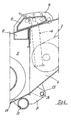
- the bottom 20 of the cutting trough 11 is in the area of the rear wall 10 with two ends Holders 21 equipped, which are interconnected by a tube 22 stabilizing.
- the free ends of the holder 21 have through holes 23 in which one Axis 24 is mounted.
- This axis 24 is of two extensions of the side wall 4 of the Inclined conveyor 2 worn.
- the entire cutting unit assembly 9 is about this axis 24 and thus also the cutter bar, not shown, depending on the crop to be harvested Gutart pivotable, depending on which of the trunnions 15 and 16 of the receiving hook 8 are gripped.
- the position of the shown with dash-dotted lines Rear wall 10 and the web plates 13, 14 shows the maximum possible pivot position Cutting trough to the feeder channel.
- the cutting unit assembly 9 is to be opened the field are set down, the axis 24 is first pulled axially. After that the inclined conveyor 2 is pivoted so far down over the piston-cylinder unit 3, until the cutting unit assembly 9 rests on the field. Then the piston rods 7 of the piston cylinder units 6 retracted, whereby the receiving hook 8 from the Loosen trunnion 15, 16.
Landscapes
- Life Sciences & Earth Sciences (AREA)
- Environmental Sciences (AREA)
- Harvester Elements (AREA)
- Combines (AREA)
- Outside Dividers And Delivering Mechanisms For Harvesters (AREA)
Abstract
Description
- Figur 1
- den vorderen Teil eines selbstfahrenden Mähdreschers in der Seitenansicht,
- Figur 2
- den in Figur 1 strichpunktierten Bereich in vergrößerter Darstellung als Schnitt nach der Linie II-II der Figur 3,
- Figur 3
- eine Draufsicht auf den in Figur 2 dargestellten Teil des Mähdreschers.
- Figur 4
- eine Darstellung in der Ebene wie Figur 2 als Schnitt nach IV-IV.
- 1
- - ein vorderer Teil
- 2
- - Schrägförderer
- 3
- - Kolbenzylindereinheit
- 4
- - Seitenwände
- 5
- - Zylinder
- 6
- - Kolbenzylindereiheiten
- 7
- - Kolbenstangen
- 8
- - Aufnahmehaken
- 9
- - schneidwerksbaugruppe
- 10
- - Rückwand
- 11
- - Schneidwerksmulde
- 12
- - Verstärkungsprofil
- 13
- - Stegplatten
- 14
- - Stegplatten
- 15
- - Tragbolzen
- 16
- - Tragbolzen
- 17
- - Kastenrahmen
- 18
- - Kastenrahmen
- 19
- - Kastenrahmen
- 20
- - Boden
- 21
- - Halter
- 22
- - Rohr
- 23
- - Durchgangsbohrungen
- 24
- - Achse
Claims (6)
- Vorrichtung zur Anbringung und Halterung einer Einrichtung zur Aufnahme von Erntegut an einem schwenkbaren Schrägförderer zur Weiterleitung des Erntegutes in eine Erntemaschine wie beispielsweise einen selbstfahrenden Mähdrescher, wobei die Vorrichtung an dem Gehäuse des Schrägförderers und zwar in seinem vorderen Bereich befestigt ist und Aufnahmehaken aufweist zum Untergreifen eines einem jeden Aufnahmehaken zugeordneten Tragbolzens, die über je zwei voneinander beabstandete Stegplatten mit dem oberen Abschluß der Rückwand der Schneidwerksmulde fest verbunden sind
dadurch gekennzeichnet,
daß jedem Aufnahmehaken mehrere mit Abstand und parallel zueinander angeordnete Tragbolzen (15, 16) zugeordnet sind und daß die Schneidwerksbaugruppe (9) im unteren Bereich der Schneidwerksmuldenrückwand (10) mit dem Schrägförderkanal (2) über eine horizontale Achse (24) schwenkbar verbunden ist. - Vorrichtung zur Aufnahme und Halterung einer Schneidwerksbaugruppe nach Anspruch 1,
dadurch gekennzeichnet,
daß Aufnahmehaken (8) in an sich bekannter Weise an frei auslaufenden Enden von Kolbenstangen (7) befestigt sind, deren Zylinder (5) mit den Seitenwänden (4) des Schrägförderers (2) verbunden sind. - Vorrichtung zur Aufnahme und Halterung einer Schneidwerksbaugruppe nach den Ansprüchen 1 und 2,
dadurch gekennzeichnet,
daß die Stegplatten (13, 14) die Schneidwerksmuldenrückwand (10) nach hinten überragen und zumindest einige der Tragbolzen (15, 16) in den nach hinten auskragenden Bereichen der Stegplatten (13, 14) vorgesehen sind. - Vorrichtung zur Aufnahme und Halterung einer Schneidwerksbaugruppe nach den Ansprüchen 1, 2 und 3
dadurch gekennzeichnet,
daß die Stegplatten (13, 14) zwecks seitlicher Aussteifung mit Kastenrahmen (17 bis 19) festverbunden sind. - Vorrichtung zur Aufnahme und Halterung einer Schneidwerksbaugruppe nach Anspruch 4,
dadurch gekennzeichnet,
daß die Kastenrahmen (17 bis 19) mit dem oberen Abschluß der Schneidwerksmuldenrückwand (10) festverbunden sind und diesen nach hinten überragen - Vorrichtung zur Aufnahme und Halterung einer Schneidwerksbaugruppe nach den Ansprüchen 1 bis 5,
dadurch gekennzeichnet,
daß der obere Abschluß der Schneidwerksmuldenrückwand (10) als über die gesamte Breite in der Schneidwerksmuldenrückwand verlaufendes Verstärkungsprofil 12 ausgebildet und mit dieser festverbunden ist.
Applications Claiming Priority (2)
| Application Number | Priority Date | Filing Date | Title |
|---|---|---|---|
| DE19949213 | 1999-10-13 | ||
| DE19949213A DE19949213A1 (de) | 1999-10-13 | 1999-10-13 | Vorrichtung zur Aufnahme und Halterung einer Schneidwerksbaugruppe am schwenkbaren Schrägförderer eines selbstfahrenden Mähdreschers |
Publications (2)
| Publication Number | Publication Date |
|---|---|
| EP1092341A1 true EP1092341A1 (de) | 2001-04-18 |
| EP1092341B1 EP1092341B1 (de) | 2004-12-01 |
Family
ID=7925401
Family Applications (1)
| Application Number | Title | Priority Date | Filing Date |
|---|---|---|---|
| EP00120980A Expired - Lifetime EP1092341B1 (de) | 1999-10-13 | 2000-09-27 | Vorrichtung zur Aufnahme und Halterung einer Schneidwerksbaugruppe am schwenkbaren Schrägförderer eines selbstfahrenden Mähdreschers |
Country Status (4)
| Country | Link |
|---|---|
| US (1) | US6318057B1 (de) |
| EP (1) | EP1092341B1 (de) |
| AT (1) | ATE283623T1 (de) |
| DE (2) | DE19949213A1 (de) |
Cited By (2)
| Publication number | Priority date | Publication date | Assignee | Title |
|---|---|---|---|---|
| EP2989882A1 (de) * | 2014-08-29 | 2016-03-02 | Deere & Company | Schrägfördereranordnung zur montage eines vorsatzes an einen mähdrescher |
| US20210392816A1 (en) * | 2018-11-16 | 2021-12-23 | Cnh Industrial America Llc | Locking mechanism for an agricultural header |
Families Citing this family (11)
| Publication number | Priority date | Publication date | Assignee | Title |
|---|---|---|---|---|
| DE10018211A1 (de) * | 2000-04-12 | 2001-11-22 | Claas Selbstfahr Erntemasch | Landwirtschaftliche Erntemaschine |
| DE10030330A1 (de) * | 2000-06-27 | 2002-01-10 | Claas Saulgau Gmbh | Landwirtschaftliche Erntemaschine |
| US6735929B2 (en) | 2002-03-18 | 2004-05-18 | Deere & Company | Multifunction latch for a combine |
| BE1019635A3 (nl) * | 2010-02-02 | 2012-09-04 | Cnh Belgium Nv | Landbouwmachine met automatische koppeling. |
| DE102010028605A1 (de) | 2010-05-05 | 2011-11-10 | Deere & Company | Antriebsanordnung für einen Erntevorsatz einer Erntemaschine |
| BE1019381A3 (nl) * | 2010-06-22 | 2012-06-05 | Cnh Belgium Nv | Oogstmachine met automatische hydraulische en elektrische koppeling voor een voorzetapparaat. |
| WO2013101863A1 (en) * | 2011-12-28 | 2013-07-04 | Agco Corporation | Fore and aft tilt for corn header |
| DE102012223769A1 (de) * | 2012-12-19 | 2014-06-26 | Deere & Company | Schrägfördererzusammenbau mit verbesserter Pendelachse |
| DE102012223770A1 (de) * | 2012-12-19 | 2014-06-26 | Deere & Company | Schrägfördererzusammenbau mit flexiblem Boden |
| US9844184B2 (en) * | 2015-03-17 | 2017-12-19 | Agco Corporation | Header position sensing system for an agricultural harvester |
| BE1022917B1 (nl) * | 2015-05-29 | 2016-10-17 | Cnh Industrial Belgium Nv | Structuur voor het dragen van de maaier van een maaidorser |
Citations (5)
| Publication number | Priority date | Publication date | Assignee | Title |
|---|---|---|---|---|
| US3474606A (en) * | 1967-05-18 | 1969-10-28 | Deere & Co | Tiltable platform for harvester |
| US3638407A (en) * | 1969-12-12 | 1972-02-01 | Int Co | Platform knife-cutting angle adjustment |
| US4280317A (en) * | 1980-04-16 | 1981-07-28 | Sperry Corporation | Adjustable coupling apparatus |
| DE4429384C1 (de) * | 1994-08-15 | 1996-02-15 | Claas Ohg | Aufnahme- und Sicherungseinrichtung für Schneidwerke |
| CH689077A5 (de) * | 1995-09-01 | 1998-09-15 | Schwaninger Kurt Ag | Hang-Maehdrescher. |
Family Cites Families (5)
| Publication number | Priority date | Publication date | Assignee | Title |
|---|---|---|---|---|
| AT287510B (de) * | 1966-10-04 | 1971-01-25 | Ernst Weichel | Ladewagen |
| GB1208285A (en) * | 1966-11-15 | 1970-10-14 | Massey Ferguson Australia Ltd | Combine harvesters having height-adjustable table |
| EP0031192A1 (de) * | 1979-08-31 | 1981-07-01 | Archie Kidd Limited | Ladewagen für landwirtschaftliches Erntegut mit Schneidvorrichtung |
| US4332127A (en) * | 1980-10-14 | 1982-06-01 | International Harvester Co. | Combine feeder drive control |
| US4707972A (en) * | 1985-06-19 | 1987-11-24 | New Holland Inc. | Movable feeder floor for combines |
-
1999
- 1999-10-13 DE DE19949213A patent/DE19949213A1/de not_active Withdrawn
-
2000
- 2000-09-26 US US09/669,139 patent/US6318057B1/en not_active Expired - Fee Related
- 2000-09-27 EP EP00120980A patent/EP1092341B1/de not_active Expired - Lifetime
- 2000-09-27 DE DE50008818T patent/DE50008818D1/de not_active Expired - Lifetime
- 2000-09-27 AT AT00120980T patent/ATE283623T1/de not_active IP Right Cessation
Patent Citations (5)
| Publication number | Priority date | Publication date | Assignee | Title |
|---|---|---|---|---|
| US3474606A (en) * | 1967-05-18 | 1969-10-28 | Deere & Co | Tiltable platform for harvester |
| US3638407A (en) * | 1969-12-12 | 1972-02-01 | Int Co | Platform knife-cutting angle adjustment |
| US4280317A (en) * | 1980-04-16 | 1981-07-28 | Sperry Corporation | Adjustable coupling apparatus |
| DE4429384C1 (de) * | 1994-08-15 | 1996-02-15 | Claas Ohg | Aufnahme- und Sicherungseinrichtung für Schneidwerke |
| CH689077A5 (de) * | 1995-09-01 | 1998-09-15 | Schwaninger Kurt Ag | Hang-Maehdrescher. |
Cited By (4)
| Publication number | Priority date | Publication date | Assignee | Title |
|---|---|---|---|---|
| EP2989882A1 (de) * | 2014-08-29 | 2016-03-02 | Deere & Company | Schrägfördereranordnung zur montage eines vorsatzes an einen mähdrescher |
| US9468148B2 (en) | 2014-08-29 | 2016-10-18 | Deere & Company | Feederhouse arrangement for mounting a header to a combine |
| US20210392816A1 (en) * | 2018-11-16 | 2021-12-23 | Cnh Industrial America Llc | Locking mechanism for an agricultural header |
| US12075728B2 (en) * | 2018-11-16 | 2024-09-03 | Cnh Industrial America Llc | Locking mechanism for an agricultural header |
Also Published As
| Publication number | Publication date |
|---|---|
| US6318057B1 (en) | 2001-11-20 |
| DE19949213A1 (de) | 2001-08-09 |
| DE50008818D1 (de) | 2005-01-05 |
| ATE283623T1 (de) | 2004-12-15 |
| EP1092341B1 (de) | 2004-12-01 |
Similar Documents
| Publication | Publication Date | Title |
|---|---|---|
| EP1709858B1 (de) | Erntevorsatz für landwirtschaftliche Erntemaschinen | |
| DE3227975C2 (de) | ||
| DE3722143C2 (de) | Gutaufnahmevorrichtung für Erntemaschinen, insbesondere für selbstfahrende Mähdrescher | |
| EP1092341B1 (de) | Vorrichtung zur Aufnahme und Halterung einer Schneidwerksbaugruppe am schwenkbaren Schrägförderer eines selbstfahrenden Mähdreschers | |
| EP1179292A1 (de) | Verfahren und Vorrichtung zum Schwenken der Abteiler von mehrteiligen landwirtschaftlichen Erntemaschinen | |
| EP3763180B1 (de) | Erntevorrichtung zum überführen derselben zwischen einer arbeitsstellung und einer transportstellung | |
| EP1062860B1 (de) | Vorrichtung für Erntefahrzeuge, insbesondere für landwirtschaftliche Aufsammelballenpressen | |
| DE3830908C2 (de) | Selbstfahrener Mähdrescher mit zweigeteiltem Schneidwerk | |
| DE202011101277U1 (de) | Mähwerkskombination | |
| DE102008042392B4 (de) | Erntevorsatz für landwirtschaftliche Erntemaschinen | |
| DE1457958B1 (de) | Loesbare Verbindung der Abgabeoeffnung einer Maehwerksbaugruppe mit der Einzugsoeffnung des vertikal verschwenkbaren Einzugskanals einer Erntemaschine | |
| DE102009017400B4 (de) | Erntemaschine | |
| DE102005006216B4 (de) | Selbstfahrende landwirtschaftliche Erntemaschine | |
| EP0066238B1 (de) | Erntemaschine zum Ernten von in Reihen stehendem Erntegut | |
| DE3522699A1 (de) | Selbstfahrende erntemaschine | |
| EP0065782A1 (de) | Reihenernteeinheit für Ernteköpfe von Erntemaschinen für in Reihen stehendes Erntegut | |
| DE2345494A1 (de) | Sammelblech-anordnung bei einem kolbenpflueck-vorsatzgeraet | |
| DE2115181A1 (de) | Mähvorsatz für die Ernte in Reihe stehender Getreidearten, der aus einer Mehrzahl von mit Einzugsorganen versehenen Pickvorrichtungen besteht, deren Abstand zueinander änderbar ist | |
| DE102007035744B4 (de) | Kombination aus einem Erntevorsatz und einem Wagen zur Abstützung des Erntevorsatzes | |
| DE202015003357U1 (de) | Schneidwerk für eine Erntemaschine | |
| DE3422426A1 (de) | Landmaschine zum verlagern von auf dem boden liegendem erntegut | |
| DE202022105171U1 (de) | Landwirtschaftliche Erntemaschine | |
| EP0116660A1 (de) | Landmaschine mit einem Mähwerk und einer Konditioniereinrichtung | |
| DE2121181A1 (de) | Verbindungsgestänge für ein Erntegut bearbeitendes landwirtschaftliches Gerät und ein hiermit zu vereinigendes Erntegut zuführendes beliebiges Anbaugerät | |
| EP0992371A1 (de) | Antriebsfahrzeug mit Koppelrahmen zur Aufnahme von Arbeitsgeräten |
Legal Events
| Date | Code | Title | Description |
|---|---|---|---|
| PUAI | Public reference made under article 153(3) epc to a published international application that has entered the european phase |
Free format text: ORIGINAL CODE: 0009012 |
|
| AK | Designated contracting states |
Kind code of ref document: A1 Designated state(s): AT BE CH CY DE DK ES FI FR GB GR IE IT LI LU MC NL PT SE |
|
| AX | Request for extension of the european patent |
Free format text: AL;LT;LV;MK;RO;SI |
|
| 17P | Request for examination filed |
Effective date: 20011018 |
|
| AKX | Designation fees paid |
Free format text: AT BE CH CY DE DK ES FI FR GB GR IE IT LI LU MC NL PT SE |
|
| GRAH | Despatch of communication of intention to grant a patent |
Free format text: ORIGINAL CODE: EPIDOS IGRA |
|
| GRAH | Despatch of communication of intention to grant a patent |
Free format text: ORIGINAL CODE: EPIDOS IGRA |
|
| 17Q | First examination report despatched |
Effective date: 20030527 |
|
| GRAJ | Information related to disapproval of communication of intention to grant by the applicant or resumption of examination proceedings by the epo deleted |
Free format text: ORIGINAL CODE: EPIDOSDIGR1 |
|
| GRAP | Despatch of communication of intention to grant a patent |
Free format text: ORIGINAL CODE: EPIDOSNIGR1 |
|
| GRAP | Despatch of communication of intention to grant a patent |
Free format text: ORIGINAL CODE: EPIDOSNIGR1 |
|
| GRAS | Grant fee paid |
Free format text: ORIGINAL CODE: EPIDOSNIGR3 |
|
| GRAA | (expected) grant |
Free format text: ORIGINAL CODE: 0009210 |
|
| AK | Designated contracting states |
Kind code of ref document: B1 Designated state(s): AT BE CH CY DE DK ES FI FR GB GR IE IT LI LU MC NL PT SE |
|
| PG25 | Lapsed in a contracting state [announced via postgrant information from national office to epo] |
Ref country code: IT Free format text: LAPSE BECAUSE OF FAILURE TO SUBMIT A TRANSLATION OF THE DESCRIPTION OR TO PAY THE FEE WITHIN THE PRE;WARNING: LAPSES OF ITALIAN PATENTS WITH EFFECTIVE DATE BEFORE 2007 MAY HAVE OCCURRED AT ANY TIME BEFORE 2007. THE CORRECT EFFECTIVE DATE MAY BE DIFFERENT FROM THE ONE RECORDED.SCRIBED TIME-LIMIT Effective date: 20041201 Ref country code: GB Free format text: LAPSE BECAUSE OF FAILURE TO SUBMIT A TRANSLATION OF THE DESCRIPTION OR TO PAY THE FEE WITHIN THE PRESCRIBED TIME-LIMIT Effective date: 20041201 Ref country code: FI Free format text: LAPSE BECAUSE OF FAILURE TO SUBMIT A TRANSLATION OF THE DESCRIPTION OR TO PAY THE FEE WITHIN THE PRESCRIBED TIME-LIMIT Effective date: 20041201 Ref country code: NL Free format text: LAPSE BECAUSE OF FAILURE TO SUBMIT A TRANSLATION OF THE DESCRIPTION OR TO PAY THE FEE WITHIN THE PRESCRIBED TIME-LIMIT Effective date: 20041201 Ref country code: IE Free format text: LAPSE BECAUSE OF FAILURE TO SUBMIT A TRANSLATION OF THE DESCRIPTION OR TO PAY THE FEE WITHIN THE PRESCRIBED TIME-LIMIT Effective date: 20041201 |
|
| REG | Reference to a national code |
Ref country code: GB Ref legal event code: FG4D Free format text: NOT ENGLISH |
|
| REG | Reference to a national code |
Ref country code: CH Ref legal event code: EP |
|
| REG | Reference to a national code |
Ref country code: IE Ref legal event code: FG4D Free format text: GERMAN |
|
| REF | Corresponds to: |
Ref document number: 50008818 Country of ref document: DE Date of ref document: 20050105 Kind code of ref document: P |
|
| PG25 | Lapsed in a contracting state [announced via postgrant information from national office to epo] |
Ref country code: SE Free format text: LAPSE BECAUSE OF FAILURE TO SUBMIT A TRANSLATION OF THE DESCRIPTION OR TO PAY THE FEE WITHIN THE PRESCRIBED TIME-LIMIT Effective date: 20050301 Ref country code: DK Free format text: LAPSE BECAUSE OF FAILURE TO SUBMIT A TRANSLATION OF THE DESCRIPTION OR TO PAY THE FEE WITHIN THE PRESCRIBED TIME-LIMIT Effective date: 20050301 Ref country code: GR Free format text: LAPSE BECAUSE OF FAILURE TO SUBMIT A TRANSLATION OF THE DESCRIPTION OR TO PAY THE FEE WITHIN THE PRESCRIBED TIME-LIMIT Effective date: 20050301 |
|
| PG25 | Lapsed in a contracting state [announced via postgrant information from national office to epo] |
Ref country code: ES Free format text: LAPSE BECAUSE OF FAILURE TO SUBMIT A TRANSLATION OF THE DESCRIPTION OR TO PAY THE FEE WITHIN THE PRESCRIBED TIME-LIMIT Effective date: 20050312 |
|
| NLV1 | Nl: lapsed or annulled due to failure to fulfill the requirements of art. 29p and 29m of the patents act | ||
| GBV | Gb: ep patent (uk) treated as always having been void in accordance with gb section 77(7)/1977 [no translation filed] |
Effective date: 20041201 |
|
| REG | Reference to a national code |
Ref country code: IE Ref legal event code: FD4D |
|
| ET | Fr: translation filed | ||
| PG25 | Lapsed in a contracting state [announced via postgrant information from national office to epo] |
Ref country code: CY Free format text: LAPSE BECAUSE OF FAILURE TO SUBMIT A TRANSLATION OF THE DESCRIPTION OR TO PAY THE FEE WITHIN THE PRESCRIBED TIME-LIMIT Effective date: 20050927 Ref country code: AT Free format text: LAPSE BECAUSE OF NON-PAYMENT OF DUE FEES Effective date: 20050927 |
|
| PG25 | Lapsed in a contracting state [announced via postgrant information from national office to epo] |
Ref country code: MC Free format text: LAPSE BECAUSE OF NON-PAYMENT OF DUE FEES Effective date: 20050930 Ref country code: CH Free format text: LAPSE BECAUSE OF NON-PAYMENT OF DUE FEES Effective date: 20050930 Ref country code: LI Free format text: LAPSE BECAUSE OF NON-PAYMENT OF DUE FEES Effective date: 20050930 Ref country code: LU Free format text: LAPSE BECAUSE OF NON-PAYMENT OF DUE FEES Effective date: 20050930 |
|
| PLBE | No opposition filed within time limit |
Free format text: ORIGINAL CODE: 0009261 |
|
| STAA | Information on the status of an ep patent application or granted ep patent |
Free format text: STATUS: NO OPPOSITION FILED WITHIN TIME LIMIT |
|
| 26N | No opposition filed |
Effective date: 20050902 |
|
| REG | Reference to a national code |
Ref country code: CH Ref legal event code: PL |
|
| PG25 | Lapsed in a contracting state [announced via postgrant information from national office to epo] |
Ref country code: PT Free format text: LAPSE BECAUSE OF NON-PAYMENT OF DUE FEES Effective date: 20050501 |
|
| REG | Reference to a national code |
Ref country code: FR Ref legal event code: PLFP Year of fee payment: 16 |
|
| PGFP | Annual fee paid to national office [announced via postgrant information from national office to epo] |
Ref country code: FR Payment date: 20150922 Year of fee payment: 16 |
|
| REG | Reference to a national code |
Ref country code: FR Ref legal event code: ST Effective date: 20170531 |
|
| REG | Reference to a national code |
Ref country code: DE Ref legal event code: R084 Ref document number: 50008818 Country of ref document: DE |
|
| PG25 | Lapsed in a contracting state [announced via postgrant information from national office to epo] |
Ref country code: FR Free format text: LAPSE BECAUSE OF NON-PAYMENT OF DUE FEES Effective date: 20160930 |
|
| PGFP | Annual fee paid to national office [announced via postgrant information from national office to epo] |
Ref country code: DE Payment date: 20170719 Year of fee payment: 18 |
|
| PGFP | Annual fee paid to national office [announced via postgrant information from national office to epo] |
Ref country code: BE Payment date: 20170921 Year of fee payment: 18 |
|
| REG | Reference to a national code |
Ref country code: DE Ref legal event code: R119 Ref document number: 50008818 Country of ref document: DE |
|
| REG | Reference to a national code |
Ref country code: BE Ref legal event code: MM Effective date: 20180930 |
|
| PG25 | Lapsed in a contracting state [announced via postgrant information from national office to epo] |
Ref country code: DE Free format text: LAPSE BECAUSE OF NON-PAYMENT OF DUE FEES Effective date: 20190402 |
|
| PG25 | Lapsed in a contracting state [announced via postgrant information from national office to epo] |
Ref country code: BE Free format text: LAPSE BECAUSE OF NON-PAYMENT OF DUE FEES Effective date: 20180930 |