EP1092089B1 - Soupape d'injection de carburant et son procede d'actionnement - Google Patents
Soupape d'injection de carburant et son procede d'actionnement Download PDFInfo
- Publication number
- EP1092089B1 EP1092089B1 EP99964389A EP99964389A EP1092089B1 EP 1092089 B1 EP1092089 B1 EP 1092089B1 EP 99964389 A EP99964389 A EP 99964389A EP 99964389 A EP99964389 A EP 99964389A EP 1092089 B1 EP1092089 B1 EP 1092089B1
- Authority
- EP
- European Patent Office
- Prior art keywords
- actuator
- valve
- housing
- bearing element
- fuel injection
- Prior art date
- Legal status (The legal status is an assumption and is not a legal conclusion. Google has not performed a legal analysis and makes no representation as to the accuracy of the status listed.)
- Expired - Lifetime
Links
- 239000000446 fuel Substances 0.000 title claims description 59
- 238000002347 injection Methods 0.000 title claims description 26
- 239000007924 injection Substances 0.000 title claims description 26
- 238000000034 method Methods 0.000 title claims description 11
- 230000003213 activating effect Effects 0.000 title 1
- 238000007789 sealing Methods 0.000 claims description 32
- 238000002485 combustion reaction Methods 0.000 claims description 10
- 230000008859 change Effects 0.000 claims description 3
- 230000008901 benefit Effects 0.000 description 4
- 239000000463 material Substances 0.000 description 4
- 229910001374 Invar Inorganic materials 0.000 description 3
- 229910000831 Steel Inorganic materials 0.000 description 3
- 238000010586 diagram Methods 0.000 description 3
- 230000036316 preload Effects 0.000 description 3
- 230000008569 process Effects 0.000 description 3
- 239000010959 steel Substances 0.000 description 3
- 230000009471 action Effects 0.000 description 2
- 230000005540 biological transmission Effects 0.000 description 2
- 230000006835 compression Effects 0.000 description 2
- 238000007906 compression Methods 0.000 description 2
- 238000013461 design Methods 0.000 description 2
- 238000011161 development Methods 0.000 description 2
- 230000018109 developmental process Effects 0.000 description 2
- 238000010438 heat treatment Methods 0.000 description 2
- 238000004519 manufacturing process Methods 0.000 description 2
- 239000000243 solution Substances 0.000 description 2
- 239000007921 spray Substances 0.000 description 2
- 230000009286 beneficial effect Effects 0.000 description 1
- 238000001816 cooling Methods 0.000 description 1
- 238000013016 damping Methods 0.000 description 1
- 230000001419 dependent effect Effects 0.000 description 1
- 230000000694 effects Effects 0.000 description 1
- 238000005516 engineering process Methods 0.000 description 1
- 230000002349 favourable effect Effects 0.000 description 1
- 239000012530 fluid Substances 0.000 description 1
- 238000011835 investigation Methods 0.000 description 1
- 230000007774 longterm Effects 0.000 description 1
- 239000004033 plastic Substances 0.000 description 1
- 229920003023 plastic Polymers 0.000 description 1
- 230000003252 repetitive effect Effects 0.000 description 1
- 230000004044 response Effects 0.000 description 1
- 238000012546 transfer Methods 0.000 description 1
- 238000013519 translation Methods 0.000 description 1
- 239000002918 waste heat Substances 0.000 description 1
Images


Classifications
-
- F—MECHANICAL ENGINEERING; LIGHTING; HEATING; WEAPONS; BLASTING
- F02—COMBUSTION ENGINES; HOT-GAS OR COMBUSTION-PRODUCT ENGINE PLANTS
- F02M—SUPPLYING COMBUSTION ENGINES IN GENERAL WITH COMBUSTIBLE MIXTURES OR CONSTITUENTS THEREOF
- F02M51/00—Fuel-injection apparatus characterised by being operated electrically
- F02M51/06—Injectors peculiar thereto with means directly operating the valve needle
- F02M51/0603—Injectors peculiar thereto with means directly operating the valve needle using piezoelectric or magnetostrictive operating means
Definitions
- the invention is based on a fuel injector according to the preamble of claim 1 and by a method for Actuation of a fuel injection valve according to the genus of claim 10.
- a fuel injector is known from DE-A-19 624 006.
- DE 195 38 791 A1 describes a fuel injector for fuel injection systems of internal combustion engines known in which a valve closing body with a Valve seat surface cooperates to form a sealing seat, from one Actuator is actuated by means of a valve needle.
- piezoelectric Actuators are basically their temperature expansion.
- materials have such as steel or plastics, one negative coefficient of thermal expansion. This requires that the piezoelectric actuator increases with temperature contracts as the surrounding housing expands.
- Temperature compensation is that to operate a Valve needle of the fuel injector the valve needle via a suitable connection device with the between the two actuators mounted cylinders is to be connected. This requires additional components, which embrace at least one of the actuators, whereby the Width of the fuel injector increased. Moreover if the actuators are far apart, so that in the event of an operational heating of the first piezo actuator the second actuator the thermal expansion of the first actuator is unable to compensate. Also in Long-term operation arises because of the then trained Temperature difference between the first piezo actuator and the second piezo actuator is inadequate Temperature compensation. In the embodiment of the Doctoral thesis is the temperature of the two actuators Cooling or heating elements actively adjusted. In summary this temperature compensation is expensive and for not suitable for practical use.
- valve housing in two parts from two different ones To design materials.
- one housing part made of steel and the other To manufacture housing part from Invar By suitable Length selection of the first housing part made of steel and the second Housing part from Invar should be achieved that the overall resulting thermal expansion of the housing to the Thermal expansion of the piezoelectric actuator is adjusted and thus the piezoelectric actuator and that housing surrounding the piezoelectric actuator in the same way expand depending on temperature.
- the disadvantage of this solution is the complex production of the valve housing and the relatively high cost of the Material of the second housing part, which is preferably made of Invar exists. It should also be borne in mind that the valve housing and the actuator has a different temperature can. So the piezoelectric actuator can be due its heat loss, especially when used frequently of the fuel injector and heat it up Transfer the temperature to the valve body only slowly. On the other hand, the temperature of the valve body is determined by affects the waste heat of the internal combustion engine, on which the fuel injector is installed. That kind of Temperature compensation is therefore unsatisfactory.
- DE 195 19 192 C1 describes a fuel injector known for fuel injection systems of internal combustion engines, in which an actuator has a hydraulic transmission system acts on a valve needle.
- the translation facility has a primary piston, the one has inner recess in which a secondary piston is movable is led.
- the secondary piston is with a valve needle connected, the sealing and movable in the valve housing is led.
- There is a working space with fuel in the valve housing filled by primary pistons and secondary pistons is limited.
- On the side of the The primary piston is in contact with the piezo actuator on the primary piston.
- a disadvantage of this solution is that the hydraulic Temperature compensation damped the action of the actuator is transferred to the valve needle, whereby the Response time of the valve needle extended and that Fuel injector not as a fast switching Fuel injector is usable.
- the fuel injector according to the invention can also also as a fast-switching fuel injector be used. Further advantages lie in a precise Formability of the injection process, which makes the Injection process the respective operating state and Operating requirements of the internal combustion engine are adjusted can, and in a small number of mechanically movable components, so that Fuel injector is designed to be low-wear and is easy to construct.
- the bearing element is advantageously over a Screw element fastened in the valve housing, whereby by the tightening torque of the screw element at least set one of the actuators preload leaves. This allows the pressure of the valve needle in the sealing seat or the one acting on the valve needle Set opening force for unactuated actuators in a defined manner. This is particularly useful in connection with the elastically deformable support element. This can also do that Ratio of the preloads of the two actuators can be set.
- the actuators are advantageous in an elongated Actuator housing arranged, the actuator housing at least one on the side of the actuator housing Longitudinal recess of the actuator housing through which the bearing element protrudes, wherein the bearing element in the recess in the longitudinal direction of the actuator housing is movable.
- the two actuators can be preloaded act on what is beneficial to operational reliability of the fuel injector affects because unfavorable tensile loads on the actuators can be avoided.
- the actuators in the housing can be cheaper Way to be pre-assembled.
- the recess is also the actuator housing Bearing element guided in the valve housing.
- the actuator housing is a inflow-side housing plate, a sealing seat side Housing plate and a tubular housing wall, which the has elongated recess, comprises, wherein at least one of the actuators via at least one of the Housing plates act on the valve needle. This leaves the actuator housing is compact in the Install the fuel injector, being a cheap one Power transmission to the valve needle is given.
- the actuator arranged on one side of the bearing element advantageously experiences one when the temperature changes the bearing element directed extension, which one at the same temperature change generated on the bearing element directed extension of the on the other side of the Bearing element arranged actuator compensated. This will a particularly good temperature compensation.
- the method according to the invention for actuating a fuel injector with the characteristic features of the Claim 10 has the advantage that the closing and opening the sealing seat can be actively controlled in both directions, without the need for additional components.
- valve needle is advantageously closed when the second electrical actuation voltage is switched off of the second actuator. This allows the whole to operate energy used to close the first actuator Sealing seat can be used, which makes the closing process is simplified.
- the sealing seat is opened in an advantageous manner up to a first opening cut by switching off the first actuation voltage of the first actuator switched off second actuation voltage of the second Actuator, and opening the sealing seat up to a second Opening cross-section is made by loading the second Actuator with an electrical actuation voltage switched off first actuation voltage of the first actuator.
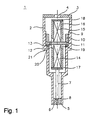
- Fuel injector 1 shows an axial sectional view Fuel injector according to the invention 1.
- Das Fuel injection valve 1 is used in particular for direct Injecting fuel, especially gasoline, into a combustion chamber of a mixture-compressing, spark-ignited Internal combustion engine as a so-called direct fuel injection valve.
- the fuel injector according to the invention is also suitable for other applications.
- the fuel injection valve 1 has a valve housing 2 on, the inflow side connected to an end plate 3 is, in the end plate 3, a fuel inlet 4th is represented simply by a hole.
- a valve seat body 5 On the spray side The end of the fuel injector 1 is located in the valve housing 2, a valve seat body 5, which has a valve seat surface 6 has.
- a valve needle 7 actuates one Valve closing body 8, which in this embodiment is formed in one piece with the valve needle 7.
- the valve closing body 8 is frustoconical and in the spray direction tapered and works with the valve seat surface 6 of the valve seat body 5 to form a sealing seat together.
- valve housing 2 Inside the valve housing 2 is an internal thread 9, into which a screw element 10 is screwed to a bearing element 11 against one on a Projection 12 of the valve housing 2 rests elastically deformable support element 13 in the valve housing 2 Fasten.
- a first actuator 14 on and on inflow-side end face of the bearing element 11 is located second actuator 15.
- the two actuators 14 and 15 are there cylindrical and are tubular Enclosed housing wall 16.
- the first actuator 14 is in contact its end facing away from the bearing element 11 on one sealing seat-side housing plate 17, which with the tubular Housing wall 16 is connected to.
- the second also lies Actuator 15 on its opposite the bearing element 11 End face on an inflow-side housing plate 18, which with the tubular housing wall 16 is connected to.
- the tubular housing wall 16 has cutouts 19, 20, through which the bearing element 11 projects.
- the administration of the fuel takes place starting from the fuel inlet 4 through, for example, a bore 21 in the bearing element 11 towards the sealing seat.
- the first actuator 14 is supported on its the end plate 3 facing end face on the bearing element 11, whereby the actuator housing 16 - 18 when the first actuator is acted upon 14 with an electrical actuation voltage in the direction the sealing seat is moved and the valve seat body 8 on the valve seat surface 6 of the valve seat body 5 is pressed, whereby the fuel injector 1 is closed.
- the resetting of the valve needle 7 can also be done via a suitably attached inside the valve housing 2 Spring element, in particular a compression spring.
- the resetting of the valve closing body 8 also by switching off the electrical actuation voltage of the actuator 15 possible. For faster resetting, a Electrical actuation voltage pulse at actuator 14 contribute.
- the bearing element 11 has a circular region 22 and two end-side, elongated regions 23, 24, which extend opposite each other by 180 °.
- Shape of the circular region 22 of the bearing element 11 the Cross section of the two actuators 14, 15 adapted so that the actuators 14, 15 are particularly favorable on the bearing element 11 can support. Since the actuators 14, 15 are shortened slightly in the axial direction in the radial direction spread, is between the actuators 14, 15 and the tubular housing wall 16, a space 25 is provided, which receives the radial expansion of the actuators 14, 15.
- the Bearing element 11 is in the elongated area 23 of the Bearing element 11 movably guided in a recess 20, likewise, the elongated region 24 of the bearing element 11 in a recess 19 out.
- the invention is not based on the exemplary embodiments described limited.
- Another configuration is also the actuators 14, 1.5, the bearing element 1.1 and the Actuator housing 16 - 18 possible.
- the at least two actuators 14, 15 of the bearing element be enclosed in sections.
- FIG. 5 shows the stroke of the valve needle 7 as a function of the stroke of the second actuator 15, the stroke of the second actuator 15 being temperature-compensated by the first actuator 14.
- the stroke ⁇ h of the two actuators 14, 15 and the valve needle 7 is plotted on the ordinate and the time t is plotted on the abscissa.
- the first actuator 14 is used exclusively for temperature compensation when the actuation voltage is switched off.
- the actuation voltage of second actuator 15 is switched on, whereby second actuator 15 expands and reaches a maximum extent at time t 2 . Since the second actuator 15 acts on the valve needle 7 without the interposition of damping elements, the valve needle 7 follows the stroke of the second actuator 15 without a time delay.
- the actuation voltage of second actuator 15 is reduced until it is completely switched off at time t 4 .
- the stroke of the valve needle 7 follows the stroke of the second actuator 15. If the temperature of the fuel injector 1 is now increased, the first actuator 14 counteracts the linear expansion of the second actuator 15, which results in a vanishing effective temperature stroke. In contrast to a non-temperature-compensated actuator 150, in which the actuator stroke is shifted by a proportion of the temperature expansion, the stroke characteristic of the temperature-stabilized actuator 15 is not shifted, so that the same valve needle stroke of the valve needle 7 results regardless of the temperature.
- valve needle lift ⁇ h of the valve needle 7 as a function of an actuation voltage U2 of the first actuator 14 and an actuation voltage U1 of the second actuator 15.
- the voltages U1, U2 and the valve needle lift ⁇ h are plotted on the ordinate and the time t on the abscissa.
- the operating voltage U2 of the first actuator 14 and the operating voltage U1 of the second actuator 15 are switched off by the time t 1 , as a result of which the valve needle 7 is in a rest position and opens the sealing seat up to a first opening cross section.
- an electrical actuation voltage U2 is applied to the first actuator 14 at time t 1 , the first actuator 14 reaching a maximum stroke at time t 2 and the sealing seat being closed.
- the sealing seat is opened at the time t 3 by applying an electrical actuation voltage U1 to the second actuator 15 up to the first opening cross section which occurs at the time t 4 .
- the actuating voltage U2 of the first actuator 14 is reduced, as a result of which the sealing seat opens further and at the point in time t 6 , at which the actuating voltage U2 of the first actuator 14 is switched off, a second opening cross section is reached.
- the actuation voltage U1 of the second actuator 15 is reduced, as a result of which the opening cross section of the sealing seat is reduced and, at time t 8 , at which the two actuation voltages U1, U2 of the two actuators 14, 15 are switched off, the first opening cross section is reached again.
- the two-stage design of the valve stroke permits a variation in the metered quantities.
Claims (12)
- Injecteur de carburant (1), en particulier pour systèmes d'injection de carburant de moteurs à combustion interne, avec un premier actionneur piézoélectrique ou magnétostrictif (14), un obturateur de soupape (8) actionnable par le premier actionneur (14) au moyen d'une aiguille (7), qui coopère avec une surface de siège de soupape (6) pour former un siège étanche, et un deuxième actionneur piézoélectrique ou magnétostrictif (15) qui agit sur l'aiguille (7) en s'opposant au premier actionneur (14),
caractérisé en ce que
les actionneurs (14, 15) sont reliés entre eux par un palier (11) monté fixe dans l'injecteur de carburant (1). - Injecteur de carburant selon la revendication 1,
caractérisé en ce que
le palier (11) présente au moins un perçage (21) pour le passage du carburant. - Injecteur de carburant selon la revendication 1 ou 2,
caractérisé en ce que
le palier (11) repose sur un épaulement (12) formé dans un boítier de soupape (2). - Injecteur de carburant selon la revendication 3,
caractérisé en ce que
le palier (11) repose sur l'épaulement (12) formé dans le boítier de soupape (2) par l'intermédiaire d'un élément de support déformable élastique (13). - Injecteur de carburant selon une des revendications 1 à 4,
caractérisé en ce qu'
au moins un des actionneurs (14, 15) est soumis à une contrainte initiale par le palier (11), l'aiguille (7) étant maintenue en position de fermeture contre le siège étanche avec une force donnée par la contrainte initiale lorsque les actionneurs (14, 15) sont au repos. - Injecteur de carburant selon la revendication 5,
caractérisé en ce que
le palier (11) est fixé par un élément fileté (10) dans le boítier de soupape (2), la contrainte initiale agissant sur au moins un des actionneurs (14, 15) se réglant par le couple de serrage de l'élément fileté (10). - Injecteur de carburant selon une des revendications 1 à 6,
caractérisé en ce que
les actionneurs (14, 15) sont disposés dans un boítier d'actionneur oblong (16, 17, 18), le boítier d'actionneur (16, 17, 18) présentant au moins un évidement (19, 20) ménagé dans le boítier d'actionneur (16, 17, 18), de forme allongée dans la direction longitudinale du boítier d'actionneur (16, 17, 18), et traverse, par l'élément d'appui (11) qui est mobile dans l'évidement (19, 20) dans la direction longitudinale du boítier d'actionneur (16, 17, 18). - Injecteur de carburant selon la revendication 7,
caractérisé en ce que
le boítier d'actionneur (16, 17, 18) comprend une plaque de boítier du côté admission (18), une plaque de boítier du côté siège étanche (17) et une paroi de boítier tubulaire (16) qui présente l'évidement oblong (19, 20), au moins un des actionneurs (14) agissant par au moins une des plaques de boítier (17) sur l'aiguille (7). - Injecteur de carburant selon une des revendications 1 à 8,
caractérisé en ce qu'
au moins le deuxième actionneur (15) monté sur un côté du palier (11) subit lors d'une variation de température une dilatation orientée vers le palier (11) qui compense une dilatation au moins du premier actionneur (14) monté sur l'autre côté du palier d'appui (11), dirigée vers le palier (11), et produite lors de la même variation de température. - Procédé d'actionnement d'un injecteur de carburant (1), en particulier systèmes d'injection de carburant de moteurs à combustion interne, avec un premier actionneur piézoélectrique ou magnétostrictif (14), un obturateur de soupape (8) activationnable par le premier actionneur (14) au moyen d'une aiguille (7) et qui coopère avec une surface de siège de soupape (6) pour former un siège étanche, et un deuxième actionneur piézoélectrique ou magnétostrictif (15) qui agit sur l'aiguille (7) en s'opposant au premier actionneur (14), ainsi qu'avec un palier (11) monté fixe dans l'injecteur de carburant (1) et qui relie les actionneurs (14, 15) l'un avec l'autre,
caractérisé par
les étapes suivantes :fermeture du siège étanche par application au premier actionneur (14) d'une première tension électrique d'activation (U2), etouverture du siège étanche par la réduction de la première tension d'activation (U2) du premier actionneur (14) et/ou par l'application au deuxième actionneur (15) d'une deuxième tension électrique d'activation (U1). - Procédé selon la revendication 10,
caractérisé en ce que
la fermeture du siège étanche se produit en coupant la deuxième tension électrique d'activation (U1) du deuxième actionneur (15). - Procédé selon la revendication 10 ou 11,
caractérisé en ce que
l'ouverture du siège étanche jusqu'à une première section d'ouverture se produit en coupant la première tension électrique d'activation (U2) du premier actionneur (14) avec la deuxième tension électrique d'activation (U1) du deuxième actionneur (15) coupée, et
l'ouverture du siège étanche jusqu'à une deuxième section d'ouverture se produit en appliquant au deuxième actionneur (15) la deuxième tension électrique d'activation (U1) avec la première tension électrique d'activation (U2) du premier actionneur (14) coupée, la deuxième section d'ouverture étant plus grande que la première section d'ouverture, en particulier deux fois plus grande.
Applications Claiming Priority (3)
| Application Number | Priority Date | Filing Date | Title |
|---|---|---|---|
| DE19918976A DE19918976A1 (de) | 1999-04-27 | 1999-04-27 | Brennstoffeinspritzventil und Verfahren zu dessen Betätigung |
| DE19918976 | 1999-04-27 | ||
| PCT/DE1999/003867 WO2000065224A1 (fr) | 1999-04-27 | 1999-12-02 | Soupape d'injection de carburant et son procede d'actionnement |
Publications (2)
| Publication Number | Publication Date |
|---|---|
| EP1092089A1 EP1092089A1 (fr) | 2001-04-18 |
| EP1092089B1 true EP1092089B1 (fr) | 2004-11-03 |
Family
ID=7905935
Family Applications (1)
| Application Number | Title | Priority Date | Filing Date |
|---|---|---|---|
| EP99964389A Expired - Lifetime EP1092089B1 (fr) | 1999-04-27 | 1999-12-02 | Soupape d'injection de carburant et son procede d'actionnement |
Country Status (6)
| Country | Link |
|---|---|
| US (1) | US6749126B1 (fr) |
| EP (1) | EP1092089B1 (fr) |
| JP (1) | JP4469507B2 (fr) |
| KR (1) | KR20010053148A (fr) |
| DE (2) | DE19918976A1 (fr) |
| WO (1) | WO2000065224A1 (fr) |
Families Citing this family (17)
| Publication number | Priority date | Publication date | Assignee | Title |
|---|---|---|---|---|
| DE10129375B4 (de) * | 2001-06-20 | 2005-10-06 | Mtu Friedrichshafen Gmbh | Injektor mit Piezo-Aktuator |
| DE10159748B4 (de) * | 2001-12-05 | 2014-11-13 | Robert Bosch Gmbh | Brennstoffeinspritzventil |
| DE10162250A1 (de) * | 2001-12-18 | 2003-07-03 | Bosch Gmbh Robert | Brennstoffeinspritzventil |
| DE10233906A1 (de) * | 2002-07-25 | 2004-02-19 | Siemens Ag | Einspritzmodul |
| DE102004030329A1 (de) * | 2004-06-23 | 2006-01-12 | Daimlerchrysler Ag | Einspritzventil |
| DE102005037267A1 (de) * | 2005-08-08 | 2007-02-15 | Robert Bosch Gmbh | Brennstoffeinspritzventil |
| DE102005041210A1 (de) * | 2005-08-31 | 2007-03-01 | Robert Bosch Gmbh | Vorrichtung mit einem Formgedächtniselement |
| DE102009014494A1 (de) * | 2009-03-23 | 2010-10-07 | Siemens Aktiengesellschaft | Stabilisierung eines Hubs von Piezomehrschichtstapeln durch kontrollierte innere Erwärmung |
| DE102009024596A1 (de) | 2009-06-10 | 2011-04-07 | Continental Automotive Gmbh | Einspritzventil mit Übertragungseinheit |
| DE102009024595A1 (de) * | 2009-06-10 | 2011-03-24 | Continental Automotive Gmbh | Einspritzventil mit Übertragungseinheit |
| US20130068200A1 (en) * | 2011-09-15 | 2013-03-21 | Paul Reynolds | Injector Valve with Miniscule Actuator Displacement |
| WO2013060360A1 (fr) * | 2011-10-25 | 2013-05-02 | Robert Bosch Gmbh | Dispositif de commande |
| DE102012109123A1 (de) | 2012-09-27 | 2014-03-27 | Vermes Microdispensing GmbH | Dosiersystem, Dosierverfahren und Herstellungsverfahren |
| DE102015119816B4 (de) * | 2015-11-17 | 2019-07-25 | V.I.E. Systems GmbH | Piezo-Aktuator mit mehreren Piezoelementen |
| JP6707907B2 (ja) * | 2016-03-03 | 2020-06-10 | セイコーエプソン株式会社 | 流体噴射装置 |
| JP6623846B2 (ja) * | 2016-03-03 | 2019-12-25 | セイコーエプソン株式会社 | 流体噴射装置 |
| DE102018001048A1 (de) * | 2018-02-09 | 2019-08-14 | Atlas Copco Ias Gmbh | Dosierventil |
Family Cites Families (11)
| Publication number | Priority date | Publication date | Assignee | Title |
|---|---|---|---|---|
| DE1751543A1 (de) | 1968-06-15 | 1970-08-27 | Kloeckner Humboldt Deutz Ag | Elektrisch steuerbares Einspritzventil |
| IT1156079B (it) | 1982-07-15 | 1987-01-28 | Fiat Ricerche | Dispositivo di intercettamento di un fluido |
| DE3533975A1 (de) | 1985-09-24 | 1987-03-26 | Bosch Gmbh Robert | Zumessventil zur dosierung von fluessigkeiten oder gasen |
| JPS62191662A (ja) | 1986-02-18 | 1987-08-22 | Mikuni Kogyo Co Ltd | 燃料噴射弁 |
| JPH06343273A (ja) | 1993-05-31 | 1994-12-13 | Aisin Seiki Co Ltd | 圧電アクチュエータ |
| JPH08165967A (ja) | 1994-12-13 | 1996-06-25 | Aisin Seiki Co Ltd | 燃料噴射装置 |
| DE19538791C2 (de) | 1995-10-18 | 1998-04-09 | Daimler Benz Ag | Piezosteuerventil für Kraftstoffeinspritzanlagen von Brennkraftmaschinen |
| DE19624006A1 (de) | 1996-06-15 | 1997-12-18 | Mtu Friedrichshafen Gmbh | Piezoelektrischer Kraftstoffinjektor |
| DE19712923A1 (de) * | 1997-03-27 | 1998-10-01 | Bosch Gmbh Robert | Piezoelektrischer Aktor |
| DE19743299C2 (de) | 1997-09-30 | 1999-11-18 | Siemens Ag | Vorrichtung zum Steuern eines Stellgliedes |
| US6400066B1 (en) * | 2000-06-30 | 2002-06-04 | Siemens Automotive Corporation | Electronic compensator for a piezoelectric actuator |
-
1999
- 1999-04-27 DE DE19918976A patent/DE19918976A1/de not_active Withdrawn
- 1999-12-02 WO PCT/DE1999/003867 patent/WO2000065224A1/fr not_active Application Discontinuation
- 1999-12-02 US US09/720,506 patent/US6749126B1/en not_active Expired - Fee Related
- 1999-12-02 EP EP99964389A patent/EP1092089B1/fr not_active Expired - Lifetime
- 1999-12-02 JP JP2000613943A patent/JP4469507B2/ja not_active Expired - Lifetime
- 1999-12-02 KR KR1020007014705A patent/KR20010053148A/ko not_active Application Discontinuation
- 1999-12-02 DE DE59911001T patent/DE59911001D1/de not_active Expired - Lifetime
Also Published As
| Publication number | Publication date |
|---|---|
| JP4469507B2 (ja) | 2010-05-26 |
| DE19918976A1 (de) | 2000-11-02 |
| WO2000065224A1 (fr) | 2000-11-02 |
| KR20010053148A (ko) | 2001-06-25 |
| JP2002543329A (ja) | 2002-12-17 |
| US6749126B1 (en) | 2004-06-15 |
| EP1092089A1 (fr) | 2001-04-18 |
| DE59911001D1 (de) | 2004-12-09 |
Similar Documents
| Publication | Publication Date | Title |
|---|---|---|
| EP1092089B1 (fr) | Soupape d'injection de carburant et son procede d'actionnement | |
| EP1115970B1 (fr) | Soupape d'injection de carburant | |
| EP1963659B1 (fr) | Injecteur de carburant dote d'un organe de soupape d'injection a actionnement direct | |
| EP1135595B1 (fr) | Soupape destinee a commander des liquides | |
| EP1705369A1 (fr) | Injecteur de carburant pour des moteurs a combustion interne | |
| EP1115971B1 (fr) | Soupape d'injection de carburant | |
| EP1593841B1 (fr) | Soupape d'injection de carburant | |
| EP1759114A1 (fr) | Injecteur de carburant a multiplication de course d'actionneur variable | |
| EP1115972B1 (fr) | Soupape d'injection de carburant | |
| DE10250720A1 (de) | Einspritzventil | |
| EP1210517B1 (fr) | Soupape servant a reguler le debit de liquides | |
| DE19947779A1 (de) | Brennstoffeinspritzventil | |
| DE102009039647A1 (de) | Kraftstoffinjektor und Kraftstoff-Einspritzsystem | |
| EP2310662B1 (fr) | Injecteur de carburant | |
| DE10353045A1 (de) | Kraftstoffeinspritzventil | |
| WO2001038712A2 (fr) | Soupape d'injection de carburant pour moteurs a combustion interne | |
| DE10002720A1 (de) | Ventil zum Steuern von Flüssigkeiten | |
| EP1664525B1 (fr) | Dispositif de dosage | |
| EP1908953B1 (fr) | Dispositif d'injection de carburant | |
| DE102006055555A1 (de) | Kraftstoffinjektor mit Piezoaktor | |
| EP1519034B1 (fr) | Soupape d'injection de carburant | |
| DE102006036782B4 (de) | Injektor | |
| DE102005024721B4 (de) | Common-Rail-Injektor | |
| WO2000017508A1 (fr) | Soupape d'injection de carburant | |
| DE10032924A1 (de) | Kraftstoffeinspritzvorrichtung für Brennkraftmaschinen |
Legal Events
| Date | Code | Title | Description |
|---|---|---|---|
| PUAI | Public reference made under article 153(3) epc to a published international application that has entered the european phase |
Free format text: ORIGINAL CODE: 0009012 |
|
| AK | Designated contracting states |
Kind code of ref document: A1 Designated state(s): AT BE CH CY DE DK ES FI FR GB GR IE IT LI LU MC NL PT SE |
|
| 17P | Request for examination filed |
Effective date: 20010502 |
|
| 17Q | First examination report despatched |
Effective date: 20031121 |
|
| GRAP | Despatch of communication of intention to grant a patent |
Free format text: ORIGINAL CODE: EPIDOSNIGR1 |
|
| RBV | Designated contracting states (corrected) |
Designated state(s): DE FR GB IT |
|
| GRAS | Grant fee paid |
Free format text: ORIGINAL CODE: EPIDOSNIGR3 |
|
| GRAA | (expected) grant |
Free format text: ORIGINAL CODE: 0009210 |
|
| AK | Designated contracting states |
Kind code of ref document: B1 Designated state(s): DE FR GB IT |
|
| REG | Reference to a national code |
Ref country code: GB Ref legal event code: FG4D Free format text: NOT ENGLISH |
|
| REF | Corresponds to: |
Ref document number: 59911001 Country of ref document: DE Date of ref document: 20041209 Kind code of ref document: P |
|
| REG | Reference to a national code |
Ref country code: IE Ref legal event code: FG4D Free format text: GERMAN |
|
| GBT | Gb: translation of ep patent filed (gb section 77(6)(a)/1977) |
Effective date: 20050224 |
|
| REG | Reference to a national code |
Ref country code: IE Ref legal event code: FD4D |
|
| ET | Fr: translation filed | ||
| PLBE | No opposition filed within time limit |
Free format text: ORIGINAL CODE: 0009261 |
|
| STAA | Information on the status of an ep patent application or granted ep patent |
Free format text: STATUS: NO OPPOSITION FILED WITHIN TIME LIMIT |
|
| 26N | No opposition filed |
Effective date: 20050804 |
|
| PGFP | Annual fee paid to national office [announced via postgrant information from national office to epo] |
Ref country code: GB Payment date: 20051220 Year of fee payment: 7 Ref country code: FR Payment date: 20051220 Year of fee payment: 7 |
|
| GBPC | Gb: european patent ceased through non-payment of renewal fee |
Effective date: 20061202 |
|
| REG | Reference to a national code |
Ref country code: FR Ref legal event code: ST Effective date: 20070831 |
|
| PG25 | Lapsed in a contracting state [announced via postgrant information from national office to epo] |
Ref country code: GB Free format text: LAPSE BECAUSE OF NON-PAYMENT OF DUE FEES Effective date: 20061202 |
|
| PG25 | Lapsed in a contracting state [announced via postgrant information from national office to epo] |
Ref country code: FR Free format text: LAPSE BECAUSE OF NON-PAYMENT OF DUE FEES Effective date: 20070102 |
|
| PGFP | Annual fee paid to national office [announced via postgrant information from national office to epo] |
Ref country code: IT Payment date: 20101227 Year of fee payment: 12 |
|
| PG25 | Lapsed in a contracting state [announced via postgrant information from national office to epo] |
Ref country code: IT Free format text: LAPSE BECAUSE OF NON-PAYMENT OF DUE FEES Effective date: 20111202 |
|
| PGFP | Annual fee paid to national office [announced via postgrant information from national office to epo] |
Ref country code: DE Payment date: 20130225 Year of fee payment: 14 |
|
| REG | Reference to a national code |
Ref country code: DE Ref legal event code: R119 Ref document number: 59911001 Country of ref document: DE |
|
| REG | Reference to a national code |
Ref country code: DE Ref legal event code: R119 Ref document number: 59911001 Country of ref document: DE Effective date: 20140701 |
|
| PG25 | Lapsed in a contracting state [announced via postgrant information from national office to epo] |
Ref country code: DE Free format text: LAPSE BECAUSE OF NON-PAYMENT OF DUE FEES Effective date: 20140701 |