EP1091875B1 - Tamper resistant closure - Google Patents
Tamper resistant closure Download PDFInfo
- Publication number
- EP1091875B1 EP1091875B1 EP99955251A EP99955251A EP1091875B1 EP 1091875 B1 EP1091875 B1 EP 1091875B1 EP 99955251 A EP99955251 A EP 99955251A EP 99955251 A EP99955251 A EP 99955251A EP 1091875 B1 EP1091875 B1 EP 1091875B1
- Authority
- EP
- European Patent Office
- Prior art keywords
- bag
- neck
- belts
- forming
- air
- Prior art date
- Legal status (The legal status is an assumption and is not a legal conclusion. Google has not performed a legal analysis and makes no representation as to the accuracy of the status listed.)
- Expired - Lifetime
Links
- 239000004033 plastic Substances 0.000 claims description 17
- 229920003023 plastic Polymers 0.000 claims description 17
- 238000000034 method Methods 0.000 claims description 11
- 235000008429 bread Nutrition 0.000 claims description 7
- 238000002844 melting Methods 0.000 claims 1
- 230000008018 melting Effects 0.000 claims 1
- 210000003739 neck Anatomy 0.000 description 78
- 238000007789 sealing Methods 0.000 description 12
- 239000000463 material Substances 0.000 description 7
- 230000001360 synchronised effect Effects 0.000 description 5
- 230000000712 assembly Effects 0.000 description 4
- 238000000429 assembly Methods 0.000 description 4
- 238000010438 heat treatment Methods 0.000 description 4
- 239000000853 adhesive Substances 0.000 description 3
- 230000001070 adhesive effect Effects 0.000 description 3
- 238000005192 partition Methods 0.000 description 3
- 239000002390 adhesive tape Substances 0.000 description 2
- 238000011109 contamination Methods 0.000 description 2
- 230000001276 controlling effect Effects 0.000 description 2
- 238000013021 overheating Methods 0.000 description 2
- 238000003466 welding Methods 0.000 description 2
- 241001589086 Bellapiscis medius Species 0.000 description 1
- 239000004809 Teflon Substances 0.000 description 1
- 229920006362 Teflon® Polymers 0.000 description 1
- 235000015173 baked goods and baking mixes Nutrition 0.000 description 1
- 239000003990 capacitor Substances 0.000 description 1
- 238000004140 cleaning Methods 0.000 description 1
- 238000010276 construction Methods 0.000 description 1
- 238000005485 electric heating Methods 0.000 description 1
- 229920002457 flexible plastic Polymers 0.000 description 1
- 238000003825 pressing Methods 0.000 description 1
- 238000007639 printing Methods 0.000 description 1
- 230000002250 progressing effect Effects 0.000 description 1
- 230000001105 regulatory effect Effects 0.000 description 1
- 238000000926 separation method Methods 0.000 description 1
- 238000010408 sweeping Methods 0.000 description 1
- 239000012815 thermoplastic material Substances 0.000 description 1
- 238000011144 upstream manufacturing Methods 0.000 description 1
Images


Classifications
-
- B—PERFORMING OPERATIONS; TRANSPORTING
- B65—CONVEYING; PACKING; STORING; HANDLING THIN OR FILAMENTARY MATERIAL
- B65B—MACHINES, APPARATUS OR DEVICES FOR, OR METHODS OF, PACKAGING ARTICLES OR MATERIALS; UNPACKING
- B65B51/00—Devices for, or methods of, sealing or securing package folds or closures; Devices for gathering or twisting wrappers, or necks of bags
Definitions
- the invention relates to a tamper resistant closure attachment accessory to a machine for wrapping a ribbon around the gathered neck of a bag and twisting the ribbon for closing and sealing the neck of the flexible bag.
- Bag tying devices of the type disclosed in the aforementioned patents are commercially available from Burford Corporation of Maysville, Oklahoma.
- the tying devices are generally constructed to receive packages such as loaves of bread at speeds of for example over one hundred (100) packages per minute at speeds of about 108 feet per minute.
- Plastic bags containing bakery products, paper plates and ice are easily opened by removing the twisted ribbon from about the neck of the bag so that the contents of the bag are accessible.
- the bag can be resealed by manually replacing and twisting the ribbon about the neck of the bag.
- Canadian Patent application 2,064,270 discloses a method of handling a preformed, open-mouthed bag having a filled and an unfilled bag portion.
- the method comprises continuously conveying the bag through a plurality of automatic bag handling stations where the unfilled bag portion is gripped to produce a flattening of the unfilled bag portion with the bag mouth in an essentially unstressed condition.
- the bag mouth is then sealed and a reusable bag closure is applied to the unfilled portion of the bag.
- U.S. Patent No. 3,576,694 discloses a method of forming a linear seal between two layers of a thermoplastic material. The method comprises gripping the layers and progressing the gripped layers. The path of the progress is successively intercepted by directing a plurality of jets of hot air from both sides of the layers.
- U.S. Patent No. 5,816,019 discloses a hot air heat-sealing machine for heat-sealing pieces of heat-sealable material.
- the machine includes a heat source for delivering hot air; presser means for pressing the pieces of material against each other, the heat source being located upstream of the presser means; and drive means and guide means for driving and guiding the pieces along a guide axis towards the heat source, so that they face each other and are spaced apart from each other, such that when they pass the heat source it lies between the two facing pieces to be heat sealed.
- U.S. Patent No. 5,600,938 discloses apparatus for sealing a plurality of spaced spots across the flattened open end of a filled plastic bag.
- the bag is moved along a conveyor past a sealing mechanism where a plurality of spaced spots are welded or fused across the open end of the bag.
- a sealing mechanism includes a plurality of heated pins which penetrate the two layers of the open end of the bag while the end of the bag is substantially flat. These pins then move along with the bag in synchronism with the conveyor while the fusing occurs.
- the sealing is accomplished by using a wheel having heated pins around its periphery and the wheel is rotated so that its tangential speed is in synchronism with the conveyor to successively make spaced fused spots across the generally flat open end of the bag.
- the apparatus seals a plurality of spaced spots to only delicately seal the bag to show evidence of tampering by breaking the seal but allow the bag to be opened without tearing or destroying the bag.
- U. S. Patent No. 5,741,075 describes a package comprising a flexible plastic bag and a label, the bag having a closed end, the closed end being openable to provide an opening for access to the contents of the package, wherein, the closed end of the package is initially sealed at a sealing area and, wherein, the sealing area is provided with a line of perforations to define the opening and reclosable by means of the label.
- the label is disclosed as having on one face two areas of adhesive separated by a non-adhesive area extending across substantially the whole width of the label, the adhesive areas being adapted to adhere to the package, one to each side of the line of perforations.
- a satisfactory method and apparatus for forming the seal and the line of perforations to provide an initial tamper-evident tear-off strip is not disclosed.
- the present invention provides a method and apparatus for forming a tamper resistant seal on a plastic bag as recited in the appended claims.
- the apparatus for forming the tamper resistant seal is preferably mounted on a bag tyer, for example of the type disclosed in U. S. Patent No. 5,483,134. Gathering belts are mounted on pulleys synchronized with the gathering belts in the bag neck tying device.
- the bag neck is flattened adjacent the gathering belts and the flattened bag neck moves adjacent a roller which has projections for forming a row of perforations in the neck of the bag.
- the bag moves between a pair of manifolds through which heated air flows to impinge against upper and lower surfaces of the bag neck for sealing the bag.
- the manifolds do not contact the surface of the bag such that the bag neck can be sealed even though printing ink on the surface of the bag may not have dried or cured or if the heat softens the ink.
- the neck of the bag moves through the tying device where the neck of the bag is gathered, tied and ejected from the tying device in conventional manner.
- closure means such as plastic wireless twist ties, plastic clips having a slot or adhesive tape may be attached to the gathered neck of the bag.
- the closure seals the bag between the row of perforations and the contents to prevent contamination and for maintaining freshness of the contents of the bag.
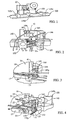
- the wire tying device generally designated by the numeral 10 in Figures 1 and 2 of the drawing is mounted adjacent a side of conveyor 300 of the type disclosed in Burford U.S. Patent No. 3,138,904 and Burford U.S. Patent No. 3,919,829, the disclosures of which are incorporated herein by reference in their entireties for all purposes.
- Conveyer 300 carries, for example, loaves 125a, 125b and 125c of bread to, through and out of wire tying device 10 in rapid succession.
- Conveyor 300 is well known to a person skilled in the art and further description is not deemed necessary except in conjunction with the drive mechanism as will be hereinafter more fully explained. It should be appreciated that other and further structures may form the conveyor.
- Loaf 125c of bread is moving toward bag tying device 10 and the neck of the bag is positioned adjacent apparatus 100 for forming a tamper resistant closure on the neck of the bag.
- Bag 125b has been moved by conveyor 300 and the gathering belts to a position where a wire-like ribbon is wrapped around the gathered neck of the bag and twisted.
- Loaf 125a of bread has moved through tying device 10 and has moved out of the tying device.
- apparatus 100 welds the sides 125x and 125y of bag 125 together to form a tamper resistant seal strip 130.
- a row 132 of perforations is formed in the neck of the bag 125 adjacent seal strip 130 to facilitate removing seal strip 130 from the bag to render the contents of the bag accessible.
- Twisted wire-like ribbon 115 closes the bag between perforated strip 132 and the contents of bag 125a.
- seal strip 130 As best illustrated in Figures 9 and 10 of the drawing, opposite sides 12x and 12y of the bag are welded together along seal strip 130 and a row 132 of perforations is formed adjacent seal strip 130.
- any conventional removable closure such as a twisted wire-like tie 115, a plastic clip having a slot that grips the neck of the bag or an adhesive tape may be attached to the neck of the bag for maintaining freshness and to prevent contamination of the contents of the bag.
- Seal strip 130 can be easily removed by tearing the bag along the row 132 of perforations.
- seal strip 130 forms a tamper evident closure for bag 125a and that the contents of the bag are not accessible until seal strip 130 is removed by tearing the bag along row 132 of perforations. Twist tie 115 can then be removed for opening the bag and reattached for resealing the bag.
- the apparatus 100 for forming a tamper resistant closure includes a pair of rollers for engaging opposite sides of the neck of the bag for forming row 132 of perforations and a pair of manifolds for directing a heated gas, such as air, to impinge against surfaces of the bag neck adjacent the row 132 of perforations for welding panels of the bag neck together to form the seal strip 130.
- a heated gas such as air
- the numeral 140p generally refers to a roller having teeth 142p formed by the periphery thereof while a roller 150p has a groove 152p formed therein for receiving teeth 142p on roller 140p.
- the teeth 142p on roller 140p perforate the neck of the bag and form row 132 of perforations in the neck of the bag.
- a pair of gathering belts 41 and 43 extend around driven rollers 140 and 144 and around a drive roller 145 mounted on shaft 146.
- Shaft 146 has a pulley 147 mounted on the opposite end thereof and is driven by a belt 25a extending around pulleys 147 and 148.
- Pulley 148 is mounted on a shaft 25 which drives the upper gathering belt 22 routed around driven pulley 24 and idler pulleys 26, 27 and 28 of the bag neck tying apparatus 10.
- Roller 150p has a groove 152p formed in the surface thereof and is driven by a pair of gathering belts 51 and 53 extending around rollers 150, 154 and 155, as illustrated in Figure 8.
- Drive roller 155 is mounted on shaft 156 which has a pulley 157 mounted on the end thereof.
- a drive belt 35a extends around pulley 158 mounted on the end of shaft 35 which drives the lower gathering belt 32 of tyer 10 which extends around driven pulley 34 and pulleys 36, 37 and 38 of the bag tying apparatus 10.
- upper gathering belts 41 and 43 and lower gathering belts 51 and 53 grippingly engage the neck of the bag adjacent opposite sides of the segment of the bag that is to be sealed to form sealed strip 130.
- Teeth 142p on roller 140p are preferably spaced from but adjacent the segment of the neck of the bag between the gathering belts 41 and 43.
- roller 140p having teeth formed thereon is driven in synchronized relation with gathering belt 22 through the belt 25a extending around pulleys 147 and 148 and that roller 150p having a groove 152p formed therein is driven in synchronized relation to the lower gathering belt by the drive belt 35a extending around pulleys 157 and 158.
- Rollers 140, 144 and 145 are mounted on a mounting plate 149 and rollers 150, 154 and 155 are mounted on a mounting plate 159.
- the opposite ends of shafts 146 and 156 are supported by mounting plates 149a and 159a.
- a top plate 149b has opposite ends secured by screws between mounting plates 149 and 149a and a side plate 149c extends vertically between mounting plates 149 and 149a and generally perpendicular to top plate 149b.
- An upper heater 160 is secured by U-bolts 162 and 164 to top plate 149b, as best illustrated in Figures 6 and 7 of the drawings.
- the rear end of the upper heater 160 extends through passage 160a formed in mounting plate 149a.
- a lower heater 170 extends through openings formed in mounting plates 159 and 159a and is secured by U-bolts 172 and 174 to a bottom mounting plate 159b adjacent a vertically extending mounting plate 159c.
- Heated air is delivered from heater 160 into an upper manifold 165 and heated air is delivered from heater 170 into a lower manifold 175.
- Manifolds 165 and 175 preferably have elongated orifices formed therein which form a row of jets of air which are projected to impinge against the surface of the neck of a bag moving between manifolds 165 and 175.
- the temperature and volume of air is selected to deliver sufficient heat for fusing panels of the bag together to form seal strip 130.
- seal strip 130 can be formed thereon. Wet or softened ink will not offset onto manifolds 165 and 175 because the manifolds do not physically engage surfaces of the neck of the bag.
- Air manifolds 165 and 175 preferably have for example twenty orifices about 0.040 inches arranged to form outlet openings which project air streams to impinge against panels 125x and 125y above and below the neck 125 of each bag for heating panels 125x and 125y to a temperature sufficient for fusing panels 125x and 125y together to form the seal strip 130.
- Heaters 160 and 170 preferably electrically heat air flowing therethrough delivered from an air supply line 180 through a pressure regulator 182, filter 184 and feed line 185, as illustrated in Figure 2 of the drawing.
- Air feed line 185 preferably passes through a control valve 186 for controlling the pressure and volume of air delivered through line 187 to heaters 160 and 170.
- the heater mount for the lower 170 is substantially a mirror image of the heater mount for heater 160 and heaters 160 and 170 are mounted on a frame to permit separation of rollers 140 and 150 in the event that a heel on a loaf of bread in bag 125 falls down into the nip between rollers 140 and 150.
- Roller 140 is spring urged downwardly toward roller 150 but can pivot upwardly if necessary to allow a heel or other obstruction to pass through the nip between rollers 140 and 150.
- Each heater 160 and 170 is preferably provided with an electric heating element connected through a thermostat which is adjustable for controlling the temperature of air delivered from heaters 160 and 170 to manifolds 165 and 175. Further, thermocouples are mounted in manifolds 165 and 175 to indicate the temperature of air supplied by heaters 160 and 170 for assuring that the temperature is maintained in a predetermined range.
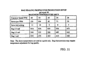
- the air temperature required for forming seal strip 130 varies depending upon the thickness and composition of the material used for forming bag 125 and the speed of conveyor 300 moving the neck of the bag between manifolds 165 and 175. As the thickness of the bag increases the temperature of air delivered through air manifolds 165 and 175 generally increases. As the speed of the conveyor increases the temperature of the air is increased to deliver a controlled volume of air and heat through manifolds 165 and 175 for forming seal strip 130.
- Air supplied through pressure regulator 182 is preferably about 25psi and heaters 160 and 170 are preferably selected to heat the volume of air flowing through manifolds 165 and 175 to a maximum temperature of for example 600° Fahrenheit.
- the thermocouples provide a read out of temperature of air flowing through manifolds 165 and 175 and the temperature of air delivered through the heaters 160 and 170 is adjustable to provide the desired quantity of heat for forming seal strip 130.
- the wire tying device forms no part of the invention claimed herein except in combination with the apparatus for forming a tamper resistant closure.
- the wire tying device generally comprises upper and lower gathering belts 22 and 32, the upper gathering belt 22 being driven by a pulley on a shaft 25 and the lower gathering belt 32 being driven by a pulley on a shaft 35, as described in U. S. Patent No. 5,483,134.
- movement of rollers in the apparatus for forming a tamper resistant closure are synchronized with the rotation of shafts 25 and 35 through belts 25a and 35a.
- the upper and lower gathering belts 22 and 32 move bags 125 along a path to a position adjacent a needle assembly, a twister hook assembly and a holder-shear assembly (not shown) for wrapping a wire-like tie around a gathered neck of the bag 120.
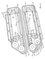
- FIG. 12 A second embodiment of the apparatus for forming a tamper resistant closure on the neck of a bag is illustrated in Figures 12 through 19.
- the parts of the apparatus are substantially the same as that of the first embodiment except that certain parts and operations have been rearranged.
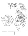
- a heater housing 200 has partition walls 202 and 204 mounted between end walls for forming a hot zone 201, and intermediate zone 203 and a cool zone 205 in the heater housing 200.
- An air filter is mounted in the intermediate zone 203 for cleaning air drawn through the intermediate zone by a blower 230 in the cool zone 205 for delivering air to heaters 260 and 270.
- Exhaust fans 208 are mounted in the hot zone 201 for exhausting spent air from heater housing 200, as will be hereinafter more fully explained.
- outboard upper gathering belt 241 and inboard upper gathering belt 243 are mounted on an upper chassis 222 and outboard lower gathering belt 251 and inboard lower gathering belt 253 are mounted on a lower chassis 225.
- the lower chassis 225, carrying belts 251 and 253 is movable from the position illustrated in Figure 12 to the position illustrated in Figure 13, if capacitive sensor 215, best illustrated in Figure 14, detects a heel or other obstruction has fallen into the neck of the bag. After the heel or other obstruction has been removed, the system is reset and the lower chassis 225 moves back to the position illustrated in Figure 12.
- the outboard upper gathering belt 241 extends around outer timing belt pulleys 240, 244, 245 and 246.
- the inboard upper gathering belt 243 extends around pulleys 240a, 244a, 245a and 246a.
- Pulleys 240and 240a are mounted on a shaft 240b
- pulleys 244 and 244a are mounted on a shaft 244b
- pulleys 245 and 245a are mounted on a shaft 245b
- pulleys 246 and 246a are mounted on a shaft 246b.
- the upper chassis 222 is formed by spaced plates 221 and 223 bolted or otherwise secured between end walls.
- the upper chassis is not movable and shafts 240b-246b are supported in bearings 227 mounted in the spaced plates 221 and 223.
- the outboard lower gathering belt 251 extends around outer pulleys 250, 254, 255 and 256.
- the inboard lower gathering belt 253 extends around pulleys 250a, 254a, 255a and 256a.
- Pulleys 250 and 250a are mounted on a shaft 250b
- pulleys 254 and 254a are mounted on a shaft 254b
- pulleys 255 and 255a are mounted on a shaft 255b
- pulleys 256 and 256a are mounted on a shaft 256b.
- the lower chassis 225 is formed by spaced plates 224 and 226 bolted or otherwise secured between slide plates which move vertically relative to the end walls.
- the lower chassis is movable and shafts 250b-256b are supported in bearings 228 mounted in the spaced plates 224 and 226.
- the bearings 227 and 228 are spaced inwardly from the timing pulleys 240 - 256b and manifolds 265 and 275 a distance sufficient to prevent excessive heating of the bearings 227 and 228 by spent air drawn vertically through the hot zone 201 in heater housing 200 by exhaust fans 208.
- the perforator wheel 220 is driven by a belt 240x which extends around a hub on the perforator wheel and is driven by a pulley (not shown) on shaft 255b.
- An air nozzle 209 is connected to a flexible tube 209a through which air is delivered from an air compressor (not shown) or other suitable source of compressed air to form a jet which flattens the neck of the bag and positions it to enter the nip between a first pair of brushes 210 and 214 positioned above the edge of the conveyor and a second pair of brushes 212 and 216 positioned below the edge of the conveyor.
- the air jet pushes side 12x of bag 12a toward side 12y of bag 125a.
- a capacitive sensor 215 is positioned between the air nozzle 209 and brushes 210-216 for sensing when a heel of a loaf of bread has fallen down into the neck of the bag. If a heel or other obstruction has fallen down into the neck of the bag, the sensor sends a signal to stop the conveyor and actuate the sealing apparatus to the non-operable position, as shown in Figures 13, 15 and 17.
- the sensor 215 is a capacitor type sensor which senses a change in mass adjacent the sensor out of a predetermined range.
- First upper and lower brushes 210 and 212 have stiff bristles and rotate in opposite directions such that the lower surface of the upper brush 210 and the upper surface of the lower brush 212 move in the same direction and engage the neck of the bag to draw the bag laterally across the conveyor until the contents of the bag engage guide bars which limit lateral movement of the bag when the contents of the bag move to engage the guide bars.
- the sweeping action of the first upper and lower brushes 210 and 212 draws the bag taut around the contents of the bag.
- the second upper and lower brushes 214 and 216 have spaced rows of angular bristles which are slightly longer than the bristles of the first upper and lower brushes 210 and 212 for moving the leading edge of the neck of the bag away from the trailing edge to flatten the neck of the bag and to evacuate air from the bag before it is sealed.
- the angularly disposed bristles are preferably about 1/8 inch larger in diameter than the bristles on the first upper and lower brushes 210 and 212.
- first pair of upper and lower brushes 210 and 212 draw the bag around the product while the second pair of upper and lower brushes 214 and 216 flatten the bag neck, evacuate air from the inside of the bag and position the leading edge of the bag neck between upper belts 241 and 243 and lower belts 251 and 253.
- the first set of brushes 210 and 212 which move the neck of the bag laterally across the conveyor tend to resiliently hold and resist movement of the neck of the bag longitudinally of the conveyor by the second pair of upper and lower brushes 214 and 216 and the gathering belts.
- the leading edge of the neck of the bag is gripped by the gathering belts and the trailing edge is pulled from between the brushes so that the neck of the bag is smoothed as it is drawn between the gathering belts and the portion of the neck of the bag that bridges the space between horizontally spaced belts 241 and 243 is substantially planar.
- the perforating assembly is formed by a perforator wheel 220 having teeth 221 spaced around its periphery positioned below the neck of the bag and an anvil 218 having a slot 217 formed therein above the neck of the bag.
- the neck of the bag is held taut between lower surfaces of belts 241 and 243 and upper surfaces of belts 251 and 253.
- Each tooth 221 on the perforator wheel 220 is shaped to make a defined cut or elongated slot in the portion of the bag neck bridging between the belts.
- An area 221a of defined length is formed between adjacent teeth 221 on the perforator wheel 220 to leave spaced areas on the neck of the bag which are not cut.
- the perforator wheel 220 is driven by a pair of belts in synchronized relation with the belts moving the bag so that every bag moving adjacent the perforator wheel is substantially identical.
- the perforator wheel 220 is mounted on a stub shaft secured in a bearing to the lower belt chassis 225. Teeth on the perforator wheel extend into the slot on the lower surface of the anvil carried by the upper chassis 222 such that the bag is supported by flat surfaces adjacent opposite sides of the perforator wheel.
- upper gathering belts 241 and 243 are mounted on an upper chassis 222 and lower gathering belts 251 and 253 are mounted on a lower chassis 225, as herein before described.
- the lower chassis 225, carrying belts 251 and 253 is movable from the position illustrated in Figure 12 to the position illustrated in Figure 13, if capacitive sensor 215 detects a heel which has fallen into the neck of the bag. After the heel or other obstruction has been removed the system is reset and the bottom chassis moves back to the position illustrated in Figure 12.
- the perforator wheel 220 is driven by a belt 240x which extends around a hub on the perforator wheel and is driven by a pulley (not shown) on shaft 255b.
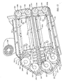
- shaft 240b which carries pulleys 240 and 240a and shaft 255b having pulleys 255 and 255a mounted thereon, are driven by a belt 320 routed around pulleys as illustrated in Figure 19 of the drawing.
- the upper pulley 302 is mounted on the end of shaft 246b.
- Shaft 245b is an idler shaft and does not have a pulley mounted on the rear end thereof.
- a pulley 304 is mounted on shaft 255b for driving timing belt pulleys 254 and 254a.
- Pulley 305 is mounted on shaft 256b for driving timing belt pulleys 350 and 350a.
- Idler pulley 306 is mounted on a stub shaft carried by the lower chassis 225.
- a direct current driven motor 315 is electrically connected to a suitable driver, such as the output from the tyer or a decoder module on the conveyor for driving belts 241, 243, 251 and 253 at a speed equal to the surface speed of the conveyor 300.
- Motor 315 has a drive pulley 310 mounted on the drive shaft for driving belt 320 which extends around an idler pulley 309, pulley 302 for driving upper belts 341 and 343, around drive pulley 304, idler pulley 305 and drive pulley 306 for driving shafts 246b and 256b, and around pulley 308.
- the upper chassis 222 carrying the upper belts 241 and 243 is stationary.
- the lower chassis 225, carrying belts 251 and 253 can be moved vertically, as illustrated in Figure 19, for moving the lower chassis 225 to an off position for separating the upper and lower pairs of belts.
- FIG 19 it should be readily apparent that when chassis 225 moves downwardly, the length of drive belt 320 is unchanged since pulleys 304, 305 and 306 rotate and advance along belt 320 as chassis 225 moves vertically. Thus, the belt tension is not changed.
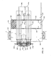
- a three-stage blower 230 delivers a high volume of pressurized air to electric heaters 260 and 270.
- Heaters 260 and 270 are preferably configured to circulate the air over heating elements for heating the air to a controlled temperature and delivering the air through diverter valves 262 and 272, respectively, to upper manifold 265 and lower manifold 275.
- Each manifold 265 and 275 has an elongated slot through which heated air is delivered to impinge against the flattened surface of the neck of the bag bridging space between outboard belts 241 and 251 and inboard belts 243 and 253.
- the perforator wheel 220 has already formed row 132 of perforations in the neck of the bag before the neck of the bag moves between upper and lower manifolds 265 and 275. This assures that the bag is perforated while it is cool and before it is heated to the point at which it might tend to stretch and deform when teeth 221 on the perforator wheel 220 engage the neck of the bag.
- the heated air flowing at a high velocity, impinges against upper and lower surfaces of the neck of the bag for welding the upper and lower surfaces together. It should be appreciated that air impinges against the portion of the bag bridged between the belts such that the molten plastic or any ink which may be softened by the hot air is not offset onto the belts or any other mechanism before the neck of the bag is cooled.
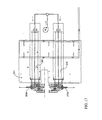
- Upper and lower diverter valves 262 and 272 are provided with spring-loaded paddles which are rotated by air cylinders from the position illustrated in Figure 16 to the position illustrated in Figure 17 when the lower chassis 225 is actuated to an inoperable position. This causes the heated air to be diverted away through exhaust ports from the neck of any bag which might be positioned adjacent the manifolds 265 and 275 when the lower chassis 225 is actuated downwardly. Diverting the air, as illustrated in Figure 17 also directs the air away from the vicinity of the belts to assure that the belts are not overheated.
- the three stage blower 230 has an intake line 230a extending through partition wall 204 for drawing air from the intermediate zone 203 through air filter 206. Air is discharged by blower 230 through lines 260a and 270a into heaters 260 and 270. Air preferably is delivered along a plurality of paths through heaters 260 and 270 to diverter valves 262 and 272. When the spring-loaded paddles are in the position illustrated in Figure 16, air is delivered through manifolds 265 and 275 to impinge against the upper and lower surfaces of the neck of the bag bridging between the inboard and outboard belts.
- Diverter valves 262 and 272 positioned immediately adjacent manifolds 265 and 275 allows the air to be diverted quickly from the manifolds to the exhaust ports and back to the manifolds. Since heated air flows continuously through diverter valves 265 and 275, the mechanism does not deviate in temperature and does not require warm-up periods when the paddle is moved from one position to the other.
- the three stage blower 230 is configured to deliver a high volume of relatively high pressure air through the heaters and manifolds 265 and 275.
- the continuous regulated supply of air through heaters 260 and 270 over heating elements assures that the air temperature and volume is maintained within parameters to assure that bag necks will be sealed as they move between manifolds 265 and 275 while assuring that excessive heat is not delivered.
- Heating elements in heaters 260 and 270 are thermostatically controlled to accommodate bags constructed of different materials and made of plastic of different thicknesses.
- brushes 210, 212, 214 and 216 are configured for flattening the neck of the bag and evacuating excess air from the inside of the bag so that the row 132 of perforation and seal strip 130 can be formed consistently on bag necks.
- the belts are preferably timing belts which have teeth 241t undercut or shortened to permit edges of the belt to extend beyond flanges on the timing belt pulleys 240 - 256a carrying the belts. This assures that the neck of the bag will not wrap around and be pinched between the belt and the flanges on the timing belt pulleys.
- a layer of soft pliable material 241x is vulcanized onto the outer surface of each belt body 241y to provide a relatively hard durable surface which is in engagement with the timing belt pulleys and to provide a relatively soft pliable surface on each belt which engages the neck of the bag. This causes the belts to grip the bag to minimize slippage as the neck of the bag is moved adjacent the perforator wheel 220 and between upper and lower manifolds 265 and 275 where seal strip 130 is formed.
- Teflon reinforced slider plates 300s are secured to mounting plates 301 bolted or otherwise secured to the upper and lower chassis 222 and 225. Belts spanning space between pulleys 344 and 345 and between pulleys 354 and 355 engage slider plates 300s which prevent deflection of the belts to assure that the belts firmly grip spaced portions of the bag neck adjacent opposite sides of upper and lower manifolds 265 and 275.
- diverter valves 262 and 272 have levers 262a and 272a extending outwardly therefrom which are engaged by a turnbuckle on the rod of a cylinder for actuating spring loaded paddles in the diverter valves from the position illustrated in Figure 16 to the position illustrated in Figure 17.
Landscapes
- Engineering & Computer Science (AREA)
- Mechanical Engineering (AREA)
- Package Closures (AREA)
- Closing Of Containers (AREA)
- Closures For Containers (AREA)
- Containers And Plastic Fillers For Packaging (AREA)
Applications Claiming Priority (3)
| Application Number | Priority Date | Filing Date | Title |
|---|---|---|---|
| US8751798P | 1998-06-01 | 1998-06-01 | |
| US87517P | 1998-06-01 | ||
| PCT/US1999/012110 WO1999062768A1 (en) | 1998-06-01 | 1999-06-01 | Tamper resistant closure |
Publications (3)
| Publication Number | Publication Date |
|---|---|
| EP1091875A1 EP1091875A1 (en) | 2001-04-18 |
| EP1091875A4 EP1091875A4 (en) | 2003-08-06 |
| EP1091875B1 true EP1091875B1 (en) | 2005-08-24 |
Family
ID=22205660
Family Applications (1)
| Application Number | Title | Priority Date | Filing Date |
|---|---|---|---|
| EP99955251A Expired - Lifetime EP1091875B1 (en) | 1998-06-01 | 1999-06-01 | Tamper resistant closure |
Country Status (10)
| Country | Link |
|---|---|
| EP (1) | EP1091875B1 (enExample) |
| JP (1) | JP4568428B2 (enExample) |
| AU (1) | AU763499B2 (enExample) |
| BR (1) | BR9910788A (enExample) |
| CA (1) | CA2333754C (enExample) |
| DE (1) | DE69926893T2 (enExample) |
| DK (1) | DK1091875T3 (enExample) |
| ES (1) | ES2249036T3 (enExample) |
| MX (1) | MXPA00011890A (enExample) |
| WO (1) | WO1999062768A1 (enExample) |
Families Citing this family (1)
| Publication number | Priority date | Publication date | Assignee | Title |
|---|---|---|---|---|
| MX2021004246A (es) * | 2018-11-08 | 2021-05-28 | Kwik Lok | Envase a prueba de manipulacion y metodos de fabricacion del mismo usando un dispositivo de sellado sin contacto. |
Family Cites Families (17)
| Publication number | Priority date | Publication date | Assignee | Title |
|---|---|---|---|---|
| US3059670A (en) | 1958-02-04 | 1962-10-23 | Charles E Burford | Wire twisting tool |
| US3138904A (en) | 1963-03-26 | 1964-06-30 | Burford Company | Method and apparatus for tying packages and wrapping materials |
| GB1200303A (en) * | 1966-10-25 | 1970-07-29 | Comtex Ltd | Improvements in or relating to electric heaters |
| JPS4819752B1 (enExample) * | 1967-04-27 | 1973-06-15 | ||
| US3919829A (en) | 1971-05-26 | 1975-11-18 | Leonard W Burford | Apparatus for tying packages and wrapping materials |
| US3990216A (en) * | 1975-05-05 | 1976-11-09 | Martin William F | Bag closing and feeding apparatus |
| JPS58107307U (ja) * | 1982-01-10 | 1983-07-21 | ナショナル住宅産業株式会社 | 包装装置 |
| JPS58163407U (ja) * | 1982-04-27 | 1983-10-31 | 野崎蒲鉾株式会社 | ミシン目付用包装装置 |
| US4682976A (en) * | 1984-04-16 | 1987-07-28 | Andrew McG. Martin | Apparatus for making easy open and reclosable bags |
| US4856258A (en) | 1986-11-21 | 1989-08-15 | Burford Corp. | Wire tying device |
| CA2064270A1 (en) * | 1992-03-27 | 1993-09-28 | Bob Davis | Tamper sealed bag with reusable closure |
| JPH0616212U (ja) * | 1992-08-05 | 1994-03-01 | トキワ工業株式会社 | フィルム包装装置 |
| US5483134A (en) | 1993-09-30 | 1996-01-09 | Burford Corporation | Ribbon sensing device for bag tyer |
| FR2725396B1 (fr) * | 1994-10-07 | 1996-12-20 | Formfil | Machine de thermosoudage |
| GB2305418B (en) | 1995-09-19 | 1998-12-02 | Allied Bakeries Ltd | Reclosable packaging |
| US5600938A (en) * | 1995-09-22 | 1997-02-11 | Kwik Lok Corporation | Sealing and bagging apparatus and method |
| AU8248598A (en) * | 1997-07-17 | 1999-02-10 | H A Holmes & Co Limited | Apparatus for heat sealing bags |
-
1999
- 1999-06-01 MX MXPA00011890A patent/MXPA00011890A/es active IP Right Grant
- 1999-06-01 BR BRPI9910788-0A patent/BR9910788A/pt not_active IP Right Cessation
- 1999-06-01 DE DE69926893T patent/DE69926893T2/de not_active Expired - Lifetime
- 1999-06-01 AU AU43248/99A patent/AU763499B2/en not_active Expired
- 1999-06-01 CA CA002333754A patent/CA2333754C/en not_active Expired - Lifetime
- 1999-06-01 JP JP2000551997A patent/JP4568428B2/ja not_active Expired - Fee Related
- 1999-06-01 ES ES99955251T patent/ES2249036T3/es not_active Expired - Lifetime
- 1999-06-01 WO PCT/US1999/012110 patent/WO1999062768A1/en not_active Ceased
- 1999-06-01 DK DK99955251T patent/DK1091875T3/da active
- 1999-06-01 EP EP99955251A patent/EP1091875B1/en not_active Expired - Lifetime
Also Published As
| Publication number | Publication date |
|---|---|
| CA2333754A1 (en) | 1999-12-09 |
| AU4324899A (en) | 1999-12-20 |
| WO1999062768A1 (en) | 1999-12-09 |
| DK1091875T3 (da) | 2005-12-19 |
| ES2249036T3 (es) | 2006-03-16 |
| AU763499B2 (en) | 2003-07-24 |
| MXPA00011890A (es) | 2005-07-15 |
| JP4568428B2 (ja) | 2010-10-27 |
| DE69926893D1 (de) | 2005-09-29 |
| EP1091875A4 (en) | 2003-08-06 |
| DE69926893T2 (de) | 2006-06-14 |
| BR9910788A (pt) | 2002-02-05 |
| EP1091875A1 (en) | 2001-04-18 |
| JP2002516789A (ja) | 2002-06-11 |
| HK1036439A1 (en) | 2002-01-04 |
| CA2333754C (en) | 2007-11-20 |
Similar Documents
| Publication | Publication Date | Title |
|---|---|---|
| EP1375380B1 (en) | Form-fill sealing machines, resealable flexible packages and methods of manufacturing resealable flexible packages | |
| EP0453522B1 (en) | Form, fill, seal and separate packaging machine for reclosable containers | |
| US5036643A (en) | Form, fill, seal and separate packaging machine for reclosable containers including means for applying zipper to web | |
| US8353147B2 (en) | Apparatus and method for manufacture of a top opening reclosable bag having a tape formed reclosable seal | |
| US5600938A (en) | Sealing and bagging apparatus and method | |
| US6807795B2 (en) | Perforated flap with dual seals | |
| EP0926069B1 (en) | Apparatus for the packaging of articles within flexible material bags | |
| US6041575A (en) | Method and apparatus for applying article to interior surface of flexible package | |
| US6854245B1 (en) | Tamper resistant closure | |
| GB2251404A (en) | Attaching closure strips to bags | |
| JP2004155432A (ja) | 製袋包装機 | |
| EP1091875B1 (en) | Tamper resistant closure | |
| HK1036439B (en) | Tamper resistant closure | |
| EP1346917A1 (en) | Flow-pack | |
| WO1983004011A1 (en) | Method and apparatus for continuous formation of reclosable article wrappers | |
| CN1349387A (zh) | 制造可重新密封袋的装置 | |
| EP0995683A1 (en) | Heatsealing and cutting mechanisms and container forming apparatus incorporating the same | |
| EP0739271A1 (en) | Flexible bag and method of making and attaching a tie | |
| CA2355671A1 (en) | Apparatus and method for applying endless bands to cartons | |
| AU652166B2 (en) | Apparatus and method for filling and sealing a product in flexible bags | |
| JP2001278230A (ja) | 小袋付き包装袋製造装置及び小袋の包装袋への取り付け方法 | |
| JPH0948078A (ja) | 製袋装置 | |
| JPH0710112A (ja) | 自動包装機 | |
| JPH0699524A (ja) | 製袋機 | |
| JPH0724800A (ja) | 包装シール用の溶断溶着板刃及び自動包装機 |
Legal Events
| Date | Code | Title | Description |
|---|---|---|---|
| PUAI | Public reference made under article 153(3) epc to a published international application that has entered the european phase |
Free format text: ORIGINAL CODE: 0009012 |
|
| 17P | Request for examination filed |
Effective date: 20001220 |
|
| AK | Designated contracting states |
Kind code of ref document: A1 Designated state(s): DE DK ES FI FR GB IE IT NL SE |
|
| A4 | Supplementary search report drawn up and despatched |
Effective date: 20030625 |
|
| RIC1 | Information provided on ipc code assigned before grant |
Ipc: 7B 65B 61/18 B Ipc: 7B 65B 51/00 A |
|
| 17Q | First examination report despatched |
Effective date: 20031119 |
|
| GRAP | Despatch of communication of intention to grant a patent |
Free format text: ORIGINAL CODE: EPIDOSNIGR1 |
|
| GRAS | Grant fee paid |
Free format text: ORIGINAL CODE: EPIDOSNIGR3 |
|
| GRAA | (expected) grant |
Free format text: ORIGINAL CODE: 0009210 |
|
| AK | Designated contracting states |
Kind code of ref document: B1 Designated state(s): DE DK ES FI FR GB IE IT NL SE |
|
| REG | Reference to a national code |
Ref country code: GB Ref legal event code: FG4D |
|
| REG | Reference to a national code |
Ref country code: IE Ref legal event code: FG4D |
|
| REF | Corresponds to: |
Ref document number: 69926893 Country of ref document: DE Date of ref document: 20050929 Kind code of ref document: P |
|
| REG | Reference to a national code |
Ref country code: SE Ref legal event code: TRGR |
|
| REG | Reference to a national code |
Ref country code: DK Ref legal event code: T3 |
|
| REG | Reference to a national code |
Ref country code: HK Ref legal event code: GR Ref document number: 1036439 Country of ref document: HK |
|
| REG | Reference to a national code |
Ref country code: ES Ref legal event code: FG2A Ref document number: 2249036 Country of ref document: ES Kind code of ref document: T3 |
|
| ET | Fr: translation filed | ||
| PLBE | No opposition filed within time limit |
Free format text: ORIGINAL CODE: 0009261 |
|
| STAA | Information on the status of an ep patent application or granted ep patent |
Free format text: STATUS: NO OPPOSITION FILED WITHIN TIME LIMIT |
|
| 26N | No opposition filed |
Effective date: 20060526 |
|
| REG | Reference to a national code |
Ref country code: FR Ref legal event code: PLFP Year of fee payment: 18 |
|
| REG | Reference to a national code |
Ref country code: FR Ref legal event code: PLFP Year of fee payment: 19 |
|
| REG | Reference to a national code |
Ref country code: FR Ref legal event code: PLFP Year of fee payment: 20 |
|
| PGFP | Annual fee paid to national office [announced via postgrant information from national office to epo] |
Ref country code: FI Payment date: 20180514 Year of fee payment: 20 Ref country code: DE Payment date: 20180515 Year of fee payment: 20 Ref country code: DK Payment date: 20180524 Year of fee payment: 20 Ref country code: IE Payment date: 20180508 Year of fee payment: 20 |
|
| PGFP | Annual fee paid to national office [announced via postgrant information from national office to epo] |
Ref country code: IT Payment date: 20180528 Year of fee payment: 20 Ref country code: NL Payment date: 20180522 Year of fee payment: 20 Ref country code: FR Payment date: 20180515 Year of fee payment: 20 |
|
| PGFP | Annual fee paid to national office [announced via postgrant information from national office to epo] |
Ref country code: SE Payment date: 20180522 Year of fee payment: 20 |
|
| PGFP | Annual fee paid to national office [announced via postgrant information from national office to epo] |
Ref country code: ES Payment date: 20180703 Year of fee payment: 20 Ref country code: GB Payment date: 20180508 Year of fee payment: 20 |
|
| REG | Reference to a national code |
Ref country code: DE Ref legal event code: R071 Ref document number: 69926893 Country of ref document: DE |
|
| REG | Reference to a national code |
Ref country code: DK Ref legal event code: EUP Effective date: 20190601 |
|
| REG | Reference to a national code |
Ref country code: NL Ref legal event code: MK Effective date: 20190531 |
|
| REG | Reference to a national code |
Ref country code: GB Ref legal event code: PE20 Expiry date: 20190531 Ref country code: IE Ref legal event code: MK9A |
|
| REG | Reference to a national code |
Ref country code: SE Ref legal event code: EUG |
|
| PG25 | Lapsed in a contracting state [announced via postgrant information from national office to epo] |
Ref country code: IE Free format text: LAPSE BECAUSE OF EXPIRATION OF PROTECTION Effective date: 20190601 |
|
| PG25 | Lapsed in a contracting state [announced via postgrant information from national office to epo] |
Ref country code: GB Free format text: LAPSE BECAUSE OF EXPIRATION OF PROTECTION Effective date: 20190531 |
|
| REG | Reference to a national code |
Ref country code: ES Ref legal event code: FD2A Effective date: 20200724 |
|
| PG25 | Lapsed in a contracting state [announced via postgrant information from national office to epo] |
Ref country code: ES Free format text: LAPSE BECAUSE OF EXPIRATION OF PROTECTION Effective date: 20190602 |