EP1090700B1 - Umgeformter Blechstreifen und Umformung mittels Profilwalzvorrichtung - Google Patents
Umgeformter Blechstreifen und Umformung mittels Profilwalzvorrichtung Download PDFInfo
- Publication number
- EP1090700B1 EP1090700B1 EP19990120154 EP99120154A EP1090700B1 EP 1090700 B1 EP1090700 B1 EP 1090700B1 EP 19990120154 EP19990120154 EP 19990120154 EP 99120154 A EP99120154 A EP 99120154A EP 1090700 B1 EP1090700 B1 EP 1090700B1
- Authority
- EP
- European Patent Office
- Prior art keywords
- metal strip
- shaped
- strip
- roll
- section
- Prior art date
- Legal status (The legal status is an assumption and is not a legal conclusion. Google has not performed a legal analysis and makes no representation as to the accuracy of the status listed.)
- Expired - Lifetime
Links
Images






Classifications
-
- F—MECHANICAL ENGINEERING; LIGHTING; HEATING; WEAPONS; BLASTING
- F28—HEAT EXCHANGE IN GENERAL
- F28D—HEAT-EXCHANGE APPARATUS, NOT PROVIDED FOR IN ANOTHER SUBCLASS, IN WHICH THE HEAT-EXCHANGE MEDIA DO NOT COME INTO DIRECT CONTACT
- F28D1/00—Heat-exchange apparatus having stationary conduit assemblies for one heat-exchange medium only, the media being in contact with different sides of the conduit wall, in which the other heat-exchange medium is a large body of fluid, e.g. domestic or motor car radiators
- F28D1/02—Heat-exchange apparatus having stationary conduit assemblies for one heat-exchange medium only, the media being in contact with different sides of the conduit wall, in which the other heat-exchange medium is a large body of fluid, e.g. domestic or motor car radiators with heat-exchange conduits immersed in the body of fluid
- F28D1/03—Heat-exchange apparatus having stationary conduit assemblies for one heat-exchange medium only, the media being in contact with different sides of the conduit wall, in which the other heat-exchange medium is a large body of fluid, e.g. domestic or motor car radiators with heat-exchange conduits immersed in the body of fluid with plate-like or laminated conduits
- F28D1/0391—Heat-exchange apparatus having stationary conduit assemblies for one heat-exchange medium only, the media being in contact with different sides of the conduit wall, in which the other heat-exchange medium is a large body of fluid, e.g. domestic or motor car radiators with heat-exchange conduits immersed in the body of fluid with plate-like or laminated conduits a single plate being bent to form one or more conduits
-
- B—PERFORMING OPERATIONS; TRANSPORTING
- B21—MECHANICAL METAL-WORKING WITHOUT ESSENTIALLY REMOVING MATERIAL; PUNCHING METAL
- B21C—MANUFACTURE OF METAL SHEETS, WIRE, RODS, TUBES, PROFILES OR LIKE SEMI-MANUFACTURED PRODUCTS OTHERWISE THAN BY ROLLING; AUXILIARY OPERATIONS USED IN CONNECTION WITH METAL-WORKING WITHOUT ESSENTIALLY REMOVING MATERIAL
- B21C37/00—Manufacture of metal sheets, rods, wire, tubes, profiles or like semi-manufactured products, not otherwise provided for; Manufacture of tubes of special shape
- B21C37/06—Manufacture of metal sheets, rods, wire, tubes, profiles or like semi-manufactured products, not otherwise provided for; Manufacture of tubes of special shape of tubes or metal hoses; Combined procedures for making tubes, e.g. for making multi-wall tubes
- B21C37/08—Making tubes with welded or soldered seams
- B21C37/083—Supply, or operations combined with supply, of strip material
-
- B—PERFORMING OPERATIONS; TRANSPORTING
- B21—MECHANICAL METAL-WORKING WITHOUT ESSENTIALLY REMOVING MATERIAL; PUNCHING METAL
- B21C—MANUFACTURE OF METAL SHEETS, WIRE, RODS, TUBES, PROFILES OR LIKE SEMI-MANUFACTURED PRODUCTS OTHERWISE THAN BY ROLLING; AUXILIARY OPERATIONS USED IN CONNECTION WITH METAL-WORKING WITHOUT ESSENTIALLY REMOVING MATERIAL
- B21C37/00—Manufacture of metal sheets, rods, wire, tubes, profiles or like semi-manufactured products, not otherwise provided for; Manufacture of tubes of special shape
- B21C37/06—Manufacture of metal sheets, rods, wire, tubes, profiles or like semi-manufactured products, not otherwise provided for; Manufacture of tubes of special shape of tubes or metal hoses; Combined procedures for making tubes, e.g. for making multi-wall tubes
- B21C37/15—Making tubes of special shape; Making tube fittings
- B21C37/155—Making tubes with non-circular section
-
- B—PERFORMING OPERATIONS; TRANSPORTING
- B21—MECHANICAL METAL-WORKING WITHOUT ESSENTIALLY REMOVING MATERIAL; PUNCHING METAL
- B21C—MANUFACTURE OF METAL SHEETS, WIRE, RODS, TUBES, PROFILES OR LIKE SEMI-MANUFACTURED PRODUCTS OTHERWISE THAN BY ROLLING; AUXILIARY OPERATIONS USED IN CONNECTION WITH METAL-WORKING WITHOUT ESSENTIALLY REMOVING MATERIAL
- B21C37/00—Manufacture of metal sheets, rods, wire, tubes, profiles or like semi-manufactured products, not otherwise provided for; Manufacture of tubes of special shape
- B21C37/06—Manufacture of metal sheets, rods, wire, tubes, profiles or like semi-manufactured products, not otherwise provided for; Manufacture of tubes of special shape of tubes or metal hoses; Combined procedures for making tubes, e.g. for making multi-wall tubes
- B21C37/15—Making tubes of special shape; Making tube fittings
- B21C37/22—Making finned or ribbed tubes by fixing strip or like material to tubes
- B21C37/225—Making finned or ribbed tubes by fixing strip or like material to tubes longitudinally-ribbed tubes
-
- B—PERFORMING OPERATIONS; TRANSPORTING
- B21—MECHANICAL METAL-WORKING WITHOUT ESSENTIALLY REMOVING MATERIAL; PUNCHING METAL
- B21D—WORKING OR PROCESSING OF SHEET METAL OR METAL TUBES, RODS OR PROFILES WITHOUT ESSENTIALLY REMOVING MATERIAL; PUNCHING METAL
- B21D5/00—Bending sheet metal along straight lines, e.g. to form simple curves
- B21D5/06—Bending sheet metal along straight lines, e.g. to form simple curves by drawing procedure making use of dies or forming-rollers, e.g. making profiles
- B21D5/10—Bending sheet metal along straight lines, e.g. to form simple curves by drawing procedure making use of dies or forming-rollers, e.g. making profiles for making tubes
- B21D5/12—Bending sheet metal along straight lines, e.g. to form simple curves by drawing procedure making use of dies or forming-rollers, e.g. making profiles for making tubes making use of forming-rollers
-
- B—PERFORMING OPERATIONS; TRANSPORTING
- B21—MECHANICAL METAL-WORKING WITHOUT ESSENTIALLY REMOVING MATERIAL; PUNCHING METAL
- B21D—WORKING OR PROCESSING OF SHEET METAL OR METAL TUBES, RODS OR PROFILES WITHOUT ESSENTIALLY REMOVING MATERIAL; PUNCHING METAL
- B21D53/00—Making other particular articles
- B21D53/02—Making other particular articles heat exchangers or parts thereof, e.g. radiators, condensers fins, headers
- B21D53/04—Making other particular articles heat exchangers or parts thereof, e.g. radiators, condensers fins, headers of sheet metal
Definitions
- the present invention relates to a V-shaped metal strip and to a formed strip such as a roll formed strip according to the preambles of claims 1 and 5 respectively, and to a bending method for bending such a strip (see for example JP-A-09068394).
- the present invention relates to a stage for forming tubes in a production system for producing heat exchangers for air conditioners, including stages for producing header pipes by press working to form a flat sheet or plate to a cylindrical shape, for producing U-shaped holders by roll forming from a metal strip, for inserting, in each holder, an inner fin formed by press forming or roll forming, for forming tubes, such as heat exchanger tubes, from each holder, for forming corrugated outer fins by a corrugate cutter, and for assembling heat exchanger tubes, outer fins, and header pipes.
- Tubes for conveying a fluid such as refrigerant is widely used in heat exchange devices such as a condenser of a refrigeration cycle for a motor vehicle, an evaporator and a radiator.
- a refrigerant tube is formed by bending a flat metal strip.
- a bending method of bending a metal strip from a flat shape into a folded shape having an approximately U-shaped cross section comprises a preceding bending step and a following bending step, according to claim 10 is proposed.
- a bending method for forming a folded metal strip may comprise a sequence of bending steps, each for applying two parallel pushing forces on a metal strip at two application points toward a V-shaped groove forming an angle.
- the distance between the two application points and the angle of the V-shaped groove are decreased step by step in the sequence of the bending steps.
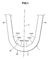
- Fig. 1 shows a formed or folded metal strip 1 for serving as a material for forming a metal tube having an elongated cross section according to the present invention.
- the metal strip 1 is made of metallic material, such as aluminum or aluminum alloy, light in weight and superior in heat conductivity.
- the formed metal strip 1 shown in Fig. 1 has a V-shaped cross section extending in a widthwise direction from an open lateral end 2 to a closed lateral end 6 as shown in Fig. 2A.
- the formed metal strip 1 has first and second (or left and right) flanges 3 terminating, respectively, at first and second (or left and right) edges 31 of the formed metal strip 1.
- the first and second flanges 3 are separated from each other and define a gap of the open end 2 extending in a longitudinal direction from a first longitudinal end of the formed strip 1 to a second longitudinal end.
- the folded metal strip 1 has first and second (or left and right) side portions or side walls 34 and a U-shaped curved portion 4 connecting the first and second side portions 34 to form the V-shaped cross section.
- first and second side portions 34 are substantially flat, and diverge, respectively, from first and second ends of the U-shaped portion 4 so as to form a V shape in cross section.
- the U-shaped curved portion 4 has an outside U-shaped surface 4a and an inside U-shaped surface 4b. Only the inside U-shaped surface 4b is formed with a plurality of fold lines P which extend in the longitudinal direction of the metal strip 1 and which are arranged in a circumferential direction of the U-shaped inside surface 4b. The inside surface 4b is bent along each of the fold lines P. Along each fold line P, two surface regions meet and form an angle such as an obtuse angle.
- the fold lines P are located away from an imaginary median plane O bisecting the V-shaped cross section of the V-shaped metal strip 1.
- the imaginary median plane appears as a center line O.
- the first pair consists of left and right (or first and second) outer fold lines P1 which are arranged substantially in a manner of bilateral symmetry with respect to the median plane O.
- the second pair consists of left and right (first and second) intermediate fold lines P2 arranged symmetrically in the manner of bilateral symmetry with respect to the median plane O .
- the third pair consists of left and right (or first and second) inner fold lines P3 arranged symmetrically in the manner of bilateral symmetry with respect to the median plane O.
- the distance between the left and right outer fold lines P1 is greater than the distance between the left and right intermediate fold lines P2.
- the height (or distance) of the outer fold lines P1 from the bottom end 6 of the formed metal strip 1 is greater than the height (or distance) of the intermediate fold lines P2.
- the distance between the left and right inner fold lines P3 is smaller than the distance between the left and right intermediate fold lines P2.
- the height (or distance) of the inner fold lines P3 from the bottom end 6 of the formed metal strip 1 is smaller than the height (or distance) of the intermediate fold lines P2.
- the formed metal strip 1 can be formed into the V shape by roll forming or extrusion.
- roll forming a metal strip is bent progressively by a sequence of a first step for bending the strip along each of the outer fold lines P1, a second step of further bending the strip along each of the intermediate fold lines P2 and a third step of further bending the strip along the inner fold lines P3.
- extrusion the cross sectional shape of Fig. 1 is obtained by setting the shape of a die.
- the formed metal strip 1 can be used as a material for forming a metal tube T for conveying a fluid such as a refrigerant for a heat transfer device such as a condenser.
- the metal tube T can be formed as shown in Figs. 2A ⁇ 2D.
- the formed metal strip 1 and an inner fin 5 are prepared as shown in Fig. 2A.
- the inner fin 5 is inserted into the formed metal strip 1 from the gap at the open end 2 of the formed metal strip 1.
- the inner fin 5 of this example is a corrugated strip of the same material as the metal strip 1 and extending in a widthwise direction from a first lateral end to a second lateral end.
- the V-shaped metal strip 1 is deformed with a press forming machine (not shown) by applying a predetermined pressure F from both sides in the thickness direction of the formed strip into a closed cross sectional shape, as shown in Fig. 2.
- a press forming machine not shown
- the left and right edges 3 of the formed metal strip 1 are brought into contact with each other, and the left and right flanges 31 are superposed together.
- the superposed flanges 31 are compressed tightly and joined together by staking or caulking, for example.
- the inner fin 5 is fixedly confined in the closed metal tube T, as shown in Fig. 2D.
- each of the fold lines P serves as an axis of bending, and promotes bending deformation of the metal strip 1.
- internal stresses in the U-shaped portion 4 are distributed among the fold lines P, so that the fold lines P function to reduce springback.
- the reduction of springback facilitates the conversion of the metal strip from the V-shaped cross section to a desired closed elongate cross section, and further facilitates the operation of fixing the flanges 3 together by brazing or welding, for example, in the later finishing step.
- the fold lines P are formed only in the inside U-shaped surface 4b, and the outside U-shaped surface 4a remains in the form of a smooth curved surface. Therefore, the outside of the U-shaped portion 4 of the metal tube T has a good appearance free of irregularities and flaws.
- the fold lines P1, P2 and P3 are arranged symmetrically on both sides of the imaginary median plane O.
- the symmetrical arrangement helps prevent stress concentration at the median plane, and prevents bending deformation along the median plane which could cause a crack.
- the symmetrical arrangement of the fold lines P promotes symmetrical folding of the metal strip and secures the desirable shape free from crush, and shape errors.
- the formed metal strip 1 can be used as a material for forming a refrigerant tube having an inner fin for a condenser as mentioned before, and as a material for forming a refrigerant tube for an evaporator and a radiator with the same effects.
- Figs. 3 ⁇ 9 shows 7 roll forming machines (or mills) 11 each having a roll set or roll pair, used in a production process according to the present invention for producing a formed metal strip as shown in Fig. 1.
- the production process of this example includes a sequence of seven roll bending steps or passes.
- Fig. 3 shows a first forming roll set 11a for the first bending step or pass.
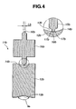
- Fig. 4 shows a second forming roll set 11b for the second bending step or pass.
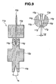
- Figs. 5, 6, 7, 8 and 9 show, respectively, third, fourth, fifth, sixth and seventh forming roll sets 11c, 11d, 11e, 11f and 11g for the third, fourth, fifth, sixth and seventh bending steps.
- Each roll set 11(11a ⁇ 11g) includes a concave roll 12(12a ⁇ 12g) with a circumferential rim formed with a V-shaped groove 13(13a ⁇ 13g), and a convex roll 15(15a ⁇ 15g) with a circumferential rim formed with a ridge 16(16a ⁇ 16g) projecting radially toward the deepest middle of the V-shaped groove of the mating concave roll.
- each roll has a shape of bilateral symmetry.
- An imaginary median plane divides the concave and convex rolls of each pair into left and right equal halves.
- Each of the V-shaped grooves 13a ⁇ 13g of the concave rolls 12a ⁇ 12g has first and second (left and right) sloping surfaces 14(14a ⁇ 14g) defining a spread angle ⁇ ( ⁇ a ⁇ ⁇ g) of the V-shaped groove as shown in Figs. 3 ⁇ 9.
- each sloping surface is a conical surface and appears as a straight line segment in the sectional views of Figs. 1 ⁇ 9.
- the spread angle is decreased gradually step by step in the order of the seven bending steps of the sequence.
- the spread angle ⁇ b of the second bending step shown in Fig. 4 is smaller than the spread angle ⁇ a of the first bending step of Fig. 3.
- the spread angle ⁇ c of the third bending step shown in Fig. 5 is smaller than the spread angle ⁇ b of the second bending step of Fig. 4.
- Each of the ridges 16a ⁇ 16g of the convex rolls 15a ⁇ 15g has first and second (left and right) edges 17(17a ⁇ 17g) confronting the first and second (left and right) sloping surfaces of the mating concave roll.
- the ridge 16 of each convex roll is in the form of a flange defined between first and second (left and right) flat surfaces extending radially. The first edge is formed between the first flat surface and a circumferential surface of the flange, and the second edge is formed between the second flat surface and the circumferential surface of the flange.
- the width of the ridge 16 measured along the axial direction defines an axial width of pressure application.
- the width of the ridge 16 is decreased gradually step by step in the order of the seven bending steps of the sequence.
- the width Lb of the second bending step shown in Fig. 4 is smaller than the width La of the first bending step of Fig. 3.
- the width Lc of the third bending step shown in Fig. 5 is smaller than the width Lb of the second bending step of Fig. 4.
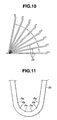
- a strip 20 is passed through the seven roll set 11a ⁇ 11g successively, and thereby bent step by step from a flat form to a U-shaped form as shown in Fig. 10.
- the strip has flanges formed by the later-mentioned method shown in Figs. 12 ⁇ 16C.
- the inside U-shaped surface of the strip 20 bent by the sequence of the bending steps has a first pair of fold lines Pa formed by the left and right edges 17a of the first convex roll 15a shown in Fig. 3.
- the left or right edge 17a applies a pressing force on the strip 20 at an application point, and forms the fold line Pa extending, at that application point, in the longitudinal direction of the strip 20.
- the inside surface is folded along the fold line Pa.
- the left and right edges 17b of the second convex roll 15b form a second pair of fold lines Pb located between the first pair of the fold lines Pa.
- the left and right edges of the subsequent bending step form a subsequent fold lines Pc ⁇ Pg (Pn).
- the shape of the formed strip 20 is simplified.
- the fold lines formed by a subsequent bending step which is any of the second through last bending steps are located between the fold lines formed by a preceding bending step which is one of the first through sixth (penultimate) bending step and which is prior to the subsequent bending step in the sequence.
- Each fold line appears as the vertex of an obtuse angle in Fig. 10.
- the outside U-shaped surface of the strip are formed by the smooth sloping surfaces 14a ⁇ 14g of the concave rolls 12a ⁇ 12g. Therefore, the outside U-shaped surface is free of fold lines and other irregularities.
- the number of the bending steps is seven.
- the invention is not limited to this. It is possible to decrease or increase the number of the bending steps.
- Fig. 12 shows a roll forming machine or roll set for forming one or more flanges in a strip, such as the flanges 3 of the metal strip 1 shown in Fig. 2A.
- the flanging roll set shown in Fig. 12 includes a first roll (selective roll) 102 and a second roll (or common roll) 104.
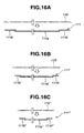
- the first roll 102 includes a center main roll section 102a having a center main roll surface for forming a flat center main section 111a in a strip 111 as shown in Fig. 16A.
- the first roll 102 further includes left and right side roll sections 102b each having a side roll surface for forming a flat flange 111b as shown in Fig. 16A.
- the center main roll section 102a is bounded axially between the left and right side roll sections 102b.
- the diameter of each side roll section 102b is greater than the diameter of the center main section 102a.
- Each flange 111b is raised from the main strip section 111a, and there is formed a step between the main section 111a and the flange 111b.
- the first roll 2 further includes left and right roll flanges 103 each abutting and sliding on the adjacent end surface of the second roll 104.
- the second roll 4 is always held in a correct position relative to the first roll 2 along the axial direction by being confined between the left and right roll flanges 103 of the first roll 2.
- the second roll 104 includes a center main roll section 104a for compressing the center main section 111a of the strip 111 with the center main roll section 102a of the first roll 102, and left and right side roll sections 104b each having a side roll surface for forming one of the flanges 111b of the strip 111. Each side roll surface is depressed below the center main surface.
- the diameter of each side roll section 104b is smaller than the diameter of the center main roll section 104a.
- the center main roll section 104a is located axially between the left and right side roll sections 104b.
- the second roll 104 further includes a left and right pair of first annular grooves 104c and a left and right pair of second annular grooves 104d.
- the first and second annular grooves 104c and 104d are located axially between the center main section 104a and the side roll section 104b.
- the first annular groove 104c is located axially between the second annular groove 104d and the side roll section 104b, and the second annular groove 104d is located axially between the center main roll section 104a and the first annular groove 104c.
- a second annular projection (or land) 104n Between the first and second annular grooves 104c and 104d, there is formed a second annular projection (or land) 104n.
- the left and right first annular grooves 104c are designed to form left and right flat flanges 111b' in a strip 111' shown in Fig. 16B. Each of the left and right first annular grooves 104c has predetermined axial position, width and depth corresponding to the position, axial width and the height of the flanges 111'.
- the left and right second annular grooves 104d are designed to form left and right flat flanges 111b" in a strip 111" shown in Fig. 16B. Each of the left and right second annular grooves 104d has predetermined axial position, width and radial depth corresponding to the position, axial width and the height of the flanges 111" shown in Fig. 16C.
- a flanged strip 111 of a wide width is formed, as shown in Fig. 16A, from a flat strip 110 such as a flat metal strip.
- the center main strip section 111a is compressed between the center main roll surfaces 102a and 104a of the first and second rolls 102 and 104.
- the left or right flange 111b of the flanged strip 111 on each of the left and right sides is formed by compression between the side roll surfaces 102b and 104b of the first and second rolls 102 and 104.
- a flanged strip 111' of a medium width is formed, as shown in Fig. 16B, from a flat strip 110'.
- the center main strip section 111a' is compressed between the center main roll surfaces 102a' and 104a of the first and second rolls 102' and 104.
- the first roll 102' of Fig. 14 has left and right annular projections 102b' each having a side roll surface. The left and right annular projections 102b' are correctly fit in the left and right first annular grooves 104c of the second roll 104, respectively, with a predetermined clearance.
- the left or right flange 111b' of the flanged strip 111' on each of the left and right sides is formed between the left or right first annular groove 104c of the second roll 104 and the side roll surface of the annular projection 102b' of the first roll 102' fit in the first annular groove 104c.
- the width of the flanged strip 111' shown in Fig. 16B is smaller than that of the flanged strip 111 shown in Fig. 15A.
- the width of the center main section 111a of the flanged strip 111' shown in Fig. 16B is smaller than that of the flanged strip 111 shown in Fig. 16A.
- the width of the left or right flange 111b' of the flanged strip 111' shown in Fig. 16B is smaller than that of the flanged strip 111 shown in Fig. 16A.
- a flanged strip 111" of a small width is formed, as shown in Fig. 16C, from a narrow flat strip 110".
- the center main strip section 111a" is compressed between the center main roll surfaces 102a" and 104a of the first and second rolls 102" and 104.
- the first roll 102" has left and right annular projections 102b" each having a side roll surface. The left and right annular projections 102b" are correctly fit in the left and right second annular grooves 104d of the second roll 104, respectively, with a predetermined clearance.
- the left or right flange 111b" of the flanged strip 111" on each of the left and right sides is formed between the left or right second annular groove 104d of the second roll 104 and the side roll surface of the annular projection 102b" of the first roll 102" fit in the second annular groove 104d.
- the width of the flanged strip 111" shown in Fig. 16C is smaller than that of the flanged strip 111' shown in Fig. 16B.
- the width of the center main section 111a" of the flanged strip 111" shown in Fig. 16C is smaller than that of the flanged strip 111' shown in Fig. 16B.
- the width of the left or right flange 111b" of the flanged strip 111" shown in Fig. 16C is equal to that of the flanged strip 111' shown in Fig. 16B.
- the first roll 102' of Fig. 14 has left and right roll flanges 103' for positioning the second roll 4 correctly along the axial direction by limiting axial movement of the second roll 104 therebetween like the flanges 3 of the first roll 102 of Figs. 12 and 13.
- the first roll 102" of Fig. 15 has left and right roll flanges 103" for positioning the second roll 4 correctly along the axial direction by limiting axial movement of the second roll 104 therebetween.
Landscapes
- Engineering & Computer Science (AREA)
- Mechanical Engineering (AREA)
- Physics & Mathematics (AREA)
- Thermal Sciences (AREA)
- General Engineering & Computer Science (AREA)
- Bending Of Plates, Rods, And Pipes (AREA)
- Wire Processing (AREA)
Claims (13)
- Ein V-förmiger Metallstreifen (1) mit einem V-förmigen Querschnitt zum Formen eines Metallrohrs mit einem geschlossenen, länglichen Querschnitt, der V-förmige Metallstreifen (1) umfasst:dadurch gekennzeichnet, dasseinen U-förmigen Abschnitt (4) mit einer U-förmig gekrümmten Innenfläche (4b) und einer U-förmig gekrümmten Außenfläche (4a),
nur die gekrümmte Innenfläche (4b) eine Vielzahl von Faltlinien (P) hat, die durch Anlegen einer Druckkraft an einem Anlagepunkt des Streifens geformt sind und sich in eine längliche Richtung des V-förmigen Metallstreifens (1) erstrecken, wobei der Streifen entlang der Faltlinien (P) gefaltet ist, und dass jede der Faltlinien (P) in Form eines Scheitels eines stumpfen Winkels in dem V-förmigen Querschnitt des V-förmigen Metallstreifens (1) ist, wobei die Faltlinien (P) von einer den V-förmigen Querschnitt halbierenden, imaginären, mittleren Ebene (O) beabstandet angeordnet sind. - Ein V-förmiger Metallstreifen (1) nach Anspruch 1, wobei die Faltlinien (P) nach Art von bilateraler Symmetrie in Bezug auf die imaginäre, mittlere Ebene (O) angeordnet sind.
- Ein V-förmiger Metallstreifen (1) nach Anspruch 1, wobei
sich der V-förmige Metallstreifen (1) in Längsrichtung von einem ersten Ende zu einem zweiten Ende erstreckt, erste und zweite Kanten (31) hat, die sich von dem ersten Ende zu dem zweiten Ende erstrecken und getrennt offen sind,
sich erste und zweite Seitenwände (34) jeweils von den ersten und zweiten Kanten zu dem U-förmigen Abschnitt (4) erstrecken, um den V-förmigen Querschnitt mit dem U-förmigen Abschnitt (4) zu formen. - Ein V-förmiger Metallstreifen (1) nach Anspruch 3, wobei der V-förmige Metallstreifen (1) erste und zweite Wangen (3) hat, die angepasst sind, um sich zum Formen des geschlossenen, länglichen Querschnitts des Metallrohrs miteinander zu verbinden, die erste Wange (3) enthält die erste Kante (31) und ist in der ersten Seitenwand (34) ausgebildet und die zweite Wange (3) enthält die zweite Kante (31) und ist in der zweiten Seitenwand (34) ausgebildet.
- Ein geformtes Metallstreifenelement zum Formen eines Flüssigkeitsdurchlasses, das geformte Metallstreifenelement umfasst:dadurch gekennzeichnet, dasseinen in zwei gefalteten Metallstreifen, der Metallstreifen umfasst:erste und zweite Kanten (31), bestimmend ein erstes seitliches Ende des gefalteten Metallstreifens und erstreckend in eine längliche Richtung des Metallstreifens von einem ersten länglichen Ende zu einem zweiten länglichen Ende des Metallstreifens (1);erste und zweite Seitenwände (34), erstreckend in Richtung der Breite des gefalteten Metallstreifens (1), jeweils von den ersten und zweiten Kanten (31) zu einem zweiten seitlichen Ende des gefalteten Metallstreifens; undeinen U-förmigen Boden (4), der das zweite seitliche Ende des gefalteten Metallstreifens bestimmt und die ersten und zweiten Seitenwände (34) verbindet und sich von dem ersten länglichen Ende zu dem zweiten länglichen Ende erstreckt, der U-förmige Boden (4) hat eine äußere U-förmige Fläche (4a) und eine innere U-förmige Fläche (4b),
die innere U-förmige Fläche (4b) mit einer Vielzahl von Faltlinien (P) geformt ist, die durch Anlegen einer Druckkraft an einem Anlagepunkt des Streifens geformt sind und sich in die längliche Richtung erstrecken, und wobei der Streifen entlang den Faltlinien (P) gefaltet ist, und
die Faltlinien (P) von einer den U-förmigen Boden (4) halbierenden, imaginären, mittleren Ebene (O) beabstandet angeordnet sind, und in der Form eines Scheitels eines stumpfen Winkels in dem U-förmigen Querschnitt (1) sind. - Ein geformtes Metallstreifenelement nach Anspruch 5, wobei der gefaltete Metallstreifen im Wesentlichen in Form von bilateraler Symmetrie in Bezug auf die den U-förmigen Boden (4) halbierende, imaginäre, mittlere Ebene (O) ist und die Faltlinien (P) paarweise angeordnet sind, jedes davon aus zwei Faltlinien (4) besteht, wobei Eine im Wesentlichen ein Spiegelbild von der Anderen in Bezug auf die imaginäre, mittlere Ebene (O) ist.
- Ein geformtes Metallstreifenelement nach Anspruch 5, wobei die ersten und zweiten Kanten (31) voneinander beabstandet sind und dazwischen eine Lücke definieren, und die ersten und zweiten Seitenwände (34) in der Form einer V-Form angeordnet sind, um einen V-förmigen Querschnitt mit dem U-förmigen Boden (4) zu formen.
- Ein geformtes Metallstreifenelement nach Anspruch 5, wobei die ersten und zweiten Kanten (31) miteinander verbunden sind, so dass der gefaltete Metallstreifen einen geschlossenen Querschnitt hat.
- Ein geformtes Metallstreifenelement nach Anspruch 8, wobei das geformte Metallstreifenelement ferner eine in dem gefalteten Metallstreifen eingeschlossene innere Rippe (5) umfasst.
- Ein Biegeverfahren zum Biegen eines Metallstreifens von einer flachen Form in eine gefaltete Form mit einem ungefährlichen U-förmigen Querschnitt, das Verfahren umfasst:einen vorangehenden Biegeschritt zum Zusammendrücken des Metallstreifens zwischen einer breiteren konkaven Walze (12) mit einem umfänglichen Rand, geformt mit einer breiteren V-förmigen Nut (13), definiert durch linke und rechte abfallenden Flächen (14), die einen breiteren Spreizwinkel () bilden und einer breiteren konvexen Walze (15) mit einem umfänglichen Rand, geformt mit einer breiteren Erhöhung (16), vorspringend zu einer Mitte der V-förmigen Nut (13) zwischen den linken und rechten abfallenden Flächen (14) und mit einer linken Kante (17) zum Pressen des Metallstreifens an einem linken vorangehenden Druckpunkt gegen die linke abfallende Fläche (14) und einer rechten Kante (17) zum Pressen des Metallstreifens an einem rechten vorangehenden Druckpunkt gegen die rechte abfallende Fläche (14), undeinen nachfolgenden Biegeschritt zum Zusammendrücken des Metallstreifens zwischen einer engeren konkaven Walze (12) mit einem umfänglichen Rand, geformt mit einer engeren V-förmigen Nut (13), definiert durch linke und rechte abfallenden Flächen (14), die einen engeren Spreizwinkel () bilden, kleiner als der breitere Spreizwinkel () des vorangehenden Biegeschritts, und einer engeren konvexen Walze (15) mit einem umfänglichen Rand, geformt mit einer engeren Erhöhung (16), vorspringend zu einer Mitte der engeren V-förmigen Nut (13) zwischen den linken und rechten abfallenden Flächen (14) und mit einer linken Kante (17) zum Pressen des Metallstreifens an einem linken nachfolgenden Druckpunkt gegen die linke abfallende Fläche (14) und einer rechten Kante zum Pressen des Metallstreifens an einem rechten nachfolgenden Druckpunkt gegen die rechte abfallende Fläche (14), die linken und rechten nachfolgenden Druckpunkte sind zwischen den linken und rechten vorangehenden Druckpunkten angeordnet, wobei der Streifen entlang Faltlinien (P) gebogen wird, die bei den Druckpunkten geformt sind und sich in Längsrichtung des Streifens erstrecken, die Faltlinien (P) sind in der Form eines Scheitels eines stumpfen Winkels in dem U-förmigen Querschnitt.
- Ein Biegeverfahren nach Anspruch 10, wobei der gemäß des vorangehenden Biegeschritts gebogene Metallstreifen linke und rechte abfallende Wände (34), erstreckend an beiden Seiten einer imaginären, mittleren Ebene (O) enthält, um so einen V-förmigen Querschnitt, halbiert von der imaginären, mittleren Ebene (O) zu formen, die linken und rechten vorangehenden und nachfolgenden Druckpunkte sind im Wesentlichen nach Art von bilateraler Symmetrie an beiden Seiten der imaginären, mittleren Ebene (O) des Metallstreifens angeordnet, der Abstand (Lb) zwischen den linken und rechten nachfolgenden Druckpunkten ist geringer, als der Abstand (La) zwischen den linken und rechten vorangehenden Druckpunkten.
- Ein Biegeverfahren nach Anspruch 10, wobei das Biegeverfahren eine Sequenz von ähnlichen Biegeschritten umfasst, inbegriffen den vorangehenden Biegeschritt und den nachfolgenden Biegeschritt zum sukzessiven Verringern des Biegewinkels des Metallstreifens (1), einen Einführungsschritt zum Einführen eines inneren Elementes (5) in einen Hohlraum des Metallstreifens, gebogen durch die Sequenz der Biegeschritte und einen Schließungsschritt zum Schließen von Kanten des Metallstreifens (1), um ein Metallrohr zu Formen, das darin das innere Element (5) enthält.
- Ein Biegeverfahren nach Anspruch 12, wobei das Biegeverfahren ferner einen Bördelschritt zum Formen von linken und rechten Wangen (3) in dem Metallstreifen (1) vor der Sequenz der Biegeschritte umfasst.
Priority Applications (2)
| Application Number | Priority Date | Filing Date | Title |
|---|---|---|---|
| DE69929194T DE69929194T2 (de) | 1999-10-08 | 1999-10-08 | Umgeformter Blechstreifen und Umformung mittels Profilwalzvorrichtung |
| EP19990120154 EP1090700B1 (de) | 1999-10-08 | 1999-10-08 | Umgeformter Blechstreifen und Umformung mittels Profilwalzvorrichtung |
Applications Claiming Priority (1)
| Application Number | Priority Date | Filing Date | Title |
|---|---|---|---|
| EP19990120154 EP1090700B1 (de) | 1999-10-08 | 1999-10-08 | Umgeformter Blechstreifen und Umformung mittels Profilwalzvorrichtung |
Publications (3)
| Publication Number | Publication Date |
|---|---|
| EP1090700A2 EP1090700A2 (de) | 2001-04-11 |
| EP1090700A3 EP1090700A3 (de) | 2002-05-15 |
| EP1090700B1 true EP1090700B1 (de) | 2005-12-28 |
Family
ID=8239163
Family Applications (1)
| Application Number | Title | Priority Date | Filing Date |
|---|---|---|---|
| EP19990120154 Expired - Lifetime EP1090700B1 (de) | 1999-10-08 | 1999-10-08 | Umgeformter Blechstreifen und Umformung mittels Profilwalzvorrichtung |
Country Status (2)
| Country | Link |
|---|---|
| EP (1) | EP1090700B1 (de) |
| DE (1) | DE69929194T2 (de) |
Families Citing this family (1)
| Publication number | Priority date | Publication date | Assignee | Title |
|---|---|---|---|---|
| PL228722B1 (pl) * | 2014-12-30 | 2018-04-30 | Valeo Autosystemy Spolka Z Ograniczona Odpowiedzialnoscia | Żebro turbulizujące dla zespołu rurowo-żebrowego przystosowanego dla wymiennika ciepła, walec kształtujący żebro turbulizujące oraz zespół składający się z rury dla wymiennika ciepła i żebra turbulizującego oraz wymiennik ciepła |
Family Cites Families (5)
| Publication number | Priority date | Publication date | Assignee | Title |
|---|---|---|---|---|
| GB1547685A (en) * | 1977-10-20 | 1979-06-27 | Hadley & Evans Sections Ltd | Manufacture of capping strip |
| JPS60247426A (ja) * | 1984-05-22 | 1985-12-07 | Showa Alum Corp | インナ−フィンを備えた偏平管の製造方法 |
| JP3346951B2 (ja) * | 1995-06-02 | 2002-11-18 | カルソニックカンセイ株式会社 | 熱交換器用チューブ |
| JP3235639B2 (ja) * | 1995-08-30 | 2001-12-04 | カルソニックカンセイ株式会社 | ディンプルチューブの製造方法 |
| JPH1015619A (ja) * | 1996-07-05 | 1998-01-20 | Sekisui Chem Co Ltd | 曲げ加工鋼板、鋼板の曲げ加工方法及び鋼板の曲げ加工用ロールフォーミング装置 |
-
1999
- 1999-10-08 EP EP19990120154 patent/EP1090700B1/de not_active Expired - Lifetime
- 1999-10-08 DE DE69929194T patent/DE69929194T2/de not_active Expired - Lifetime
Also Published As
| Publication number | Publication date |
|---|---|
| EP1090700A3 (de) | 2002-05-15 |
| DE69929194D1 (de) | 2006-02-02 |
| DE69929194T2 (de) | 2006-06-22 |
| EP1090700A2 (de) | 2001-04-11 |
Similar Documents
| Publication | Publication Date | Title |
|---|---|---|
| US6423423B2 (en) | Formed strip and roll forming | |
| US7665512B2 (en) | Flat heat exchanger tube | |
| US6325141B2 (en) | Tube | |
| JP3449897B2 (ja) | 熱交換器及びその製造方法 | |
| US6053243A (en) | Header pipe for heat exchanger and manufacturing apparatus and manufacturing method thereof | |
| JPH1085877A (ja) | 偏平チューブのロール成形方法及び装置 | |
| JP2004108571A (ja) | 継手部分を有する配管の製造方法 | |
| EP1362649A1 (de) | Verfahren und Vorrichting zum Abkanten eines Metallbandes | |
| JP2007139416A (ja) | 偏平管製造用金属板、偏平管および偏平管の製造方法 | |
| JP2024504638A (ja) | 制御された皺屈曲部を備える間接熱交換器圧力容器 | |
| US5890288A (en) | Method for making a heat exchanger tube | |
| US5353639A (en) | Method and apparatus for sizing multiple tubes | |
| KR20000034912A (ko) | 공조 시스템용 증발기 | |
| US20020074109A1 (en) | Turbulator with offset louvers and method of making same | |
| US5934365A (en) | Heat exchanger | |
| US6928847B2 (en) | Roll forming system for forming flanges in strip material | |
| JP3376501B2 (ja) | インナーフィンを備えた熱交換管の製造方法 | |
| EP1090700A2 (de) | Umgeformtes Blechstreifen und Umformung mittels Profilwalzvorrichtung | |
| JP2804156B2 (ja) | 熱交換器用伝熱管の製造方法 | |
| JP3966072B2 (ja) | 熱交換器用チューブの製造方法 | |
| US5743122A (en) | Apparatus for making a manifold for an automotive heat exchanger | |
| US5604981A (en) | Method of making an automotive evaporator | |
| JPH05164484A (ja) | 熱交換器用チューブ及び製造方法 | |
| JP3973271B2 (ja) | 受液器一体型冷媒凝縮器およびその製造方法 | |
| US2999304A (en) | Method of manufacturing heat exchangers |
Legal Events
| Date | Code | Title | Description |
|---|---|---|---|
| PUAI | Public reference made under article 153(3) epc to a published international application that has entered the european phase |
Free format text: ORIGINAL CODE: 0009012 |
|
| 17P | Request for examination filed |
Effective date: 19991008 |
|
| AK | Designated contracting states |
Kind code of ref document: A2 Designated state(s): AT BE CH CY DE DK ES FI FR GB GR IE IT LI LU MC NL PT SE |
|
| AX | Request for extension of the european patent |
Free format text: AL;LT;LV;MK;RO;SI |
|
| PUAL | Search report despatched |
Free format text: ORIGINAL CODE: 0009013 |
|
| AK | Designated contracting states |
Kind code of ref document: A3 Designated state(s): AT BE CH CY DE DK ES FI FR GB GR IE IT LI LU MC NL PT SE |
|
| AX | Request for extension of the european patent |
Free format text: AL;LT;LV;MK;RO;SI |
|
| AKX | Designation fees paid |
Designated state(s): DE FR GB |
|
| 17Q | First examination report despatched |
Effective date: 20040921 |
|
| GRAP | Despatch of communication of intention to grant a patent |
Free format text: ORIGINAL CODE: EPIDOSNIGR1 |
|
| GRAS | Grant fee paid |
Free format text: ORIGINAL CODE: EPIDOSNIGR3 |
|
| GRAA | (expected) grant |
Free format text: ORIGINAL CODE: 0009210 |
|
| AK | Designated contracting states |
Kind code of ref document: B1 Designated state(s): DE FR GB |
|
| REG | Reference to a national code |
Ref country code: GB Ref legal event code: FG4D |
|
| REF | Corresponds to: |
Ref document number: 69929194 Country of ref document: DE Date of ref document: 20060202 Kind code of ref document: P |
|
| ET | Fr: translation filed | ||
| PLBE | No opposition filed within time limit |
Free format text: ORIGINAL CODE: 0009261 |
|
| STAA | Information on the status of an ep patent application or granted ep patent |
Free format text: STATUS: NO OPPOSITION FILED WITHIN TIME LIMIT |
|
| 26N | No opposition filed |
Effective date: 20060929 |
|
| PGFP | Annual fee paid to national office [announced via postgrant information from national office to epo] |
Ref country code: DE Payment date: 20091001 Year of fee payment: 11 |
|
| PGFP | Annual fee paid to national office [announced via postgrant information from national office to epo] |
Ref country code: GB Payment date: 20091007 Year of fee payment: 11 Ref country code: FR Payment date: 20091029 Year of fee payment: 11 |
|
| GBPC | Gb: european patent ceased through non-payment of renewal fee |
Effective date: 20101008 |
|
| PG25 | Lapsed in a contracting state [announced via postgrant information from national office to epo] |
Ref country code: FR Free format text: LAPSE BECAUSE OF NON-PAYMENT OF DUE FEES Effective date: 20101102 |
|
| REG | Reference to a national code |
Ref country code: FR Ref legal event code: ST Effective date: 20110630 |
|
| PG25 | Lapsed in a contracting state [announced via postgrant information from national office to epo] |
Ref country code: GB Free format text: LAPSE BECAUSE OF NON-PAYMENT OF DUE FEES Effective date: 20101008 |
|
| REG | Reference to a national code |
Ref country code: DE Ref legal event code: R119 Ref document number: 69929194 Country of ref document: DE Effective date: 20110502 |
|
| PG25 | Lapsed in a contracting state [announced via postgrant information from national office to epo] |
Ref country code: DE Free format text: LAPSE BECAUSE OF NON-PAYMENT OF DUE FEES Effective date: 20110502 |