EP1090554A1 - Vorrichtung zur Bearbeitung von Fleisch - Google Patents
Vorrichtung zur Bearbeitung von Fleisch Download PDFInfo
- Publication number
- EP1090554A1 EP1090554A1 EP00121256A EP00121256A EP1090554A1 EP 1090554 A1 EP1090554 A1 EP 1090554A1 EP 00121256 A EP00121256 A EP 00121256A EP 00121256 A EP00121256 A EP 00121256A EP 1090554 A1 EP1090554 A1 EP 1090554A1
- Authority
- EP
- European Patent Office
- Prior art keywords
- roller
- meat
- rollers
- teeth
- cylinder
- Prior art date
- Legal status (The legal status is an assumption and is not a legal conclusion. Google has not performed a legal analysis and makes no representation as to the accuracy of the status listed.)
- Granted
Links
- 235000013372 meat Nutrition 0.000 title claims abstract description 49
- 230000001105 regulatory effect Effects 0.000 claims description 2
- 108010091431 meat tenderizer Proteins 0.000 abstract 2
- 230000000630 rising effect Effects 0.000 abstract 1
- 238000005096 rolling process Methods 0.000 description 7
- 239000012530 fluid Substances 0.000 description 4
- 235000015277 pork Nutrition 0.000 description 4
- 238000010079 rubber tapping Methods 0.000 description 3
- 239000000463 material Substances 0.000 description 2
- 238000000034 method Methods 0.000 description 2
- 235000015278 beef Nutrition 0.000 description 1
- 210000000988 bone and bone Anatomy 0.000 description 1
- 230000008878 coupling Effects 0.000 description 1
- 238000010168 coupling process Methods 0.000 description 1
- 238000005859 coupling reaction Methods 0.000 description 1
- 230000000694 effects Effects 0.000 description 1
- 235000013305 food Nutrition 0.000 description 1
- 238000003801 milling Methods 0.000 description 1
- 230000002093 peripheral effect Effects 0.000 description 1
- 239000006187 pill Substances 0.000 description 1
- 239000000725 suspension Substances 0.000 description 1
- 210000002435 tendon Anatomy 0.000 description 1
- 230000004580 weight loss Effects 0.000 description 1
Images


Classifications
-
- A—HUMAN NECESSITIES
- A22—BUTCHERING; MEAT TREATMENT; PROCESSING POULTRY OR FISH
- A22C—PROCESSING MEAT, POULTRY, OR FISH
- A22C9/00—Apparatus for tenderising meat, e.g. ham
- A22C9/004—Apparatus for tenderising meat, e.g. ham by massaging
Definitions
- the invention relates to a meat roller and a device for processing Pieces of meat.
- the device is used, in particular, for wear and tear with simultaneous increase in area of fresh meat without bone in the food sector.
- the structure of the fresh meat processed with such a device becomes sustainable changed or loosened (gelled), and the meat looks tender and when eaten tastier.
- fresh meat of all kinds but mainly meat from Beef and pork, a sustainable quality improvement is achieved.
- DE-A 33 44 284 describes a device for treating meat or ham known, which is provided with a frame in which at least two rotating in opposite directions and are arranged at a distance from adjacent rollers, between which the Treating good is carried out.
- the rollers are designed as pressure rollers and the distance between them is adjustable.
- the pressure rollers can be replaced in the Be attached to the frame, which is why each pressure roller on the drive side via a quick coupling is connected to the drive shaft and on the other side in a detachable with the bearing arrangement connected to the frame is mounted.
- the printing rollers can be on your Peripheral walls can be provided with ribs, knobs, projections or the like.
- the ribs extending at least partially over the length of the pressure rollers are in the Cross-section at least approximately rectangular, pointed or truncated cone-like.
- the rolling process leads to an effective surface enlargement of the processed Fresh meat (e.g. pork cutlet, pork neck steaks, Pork loin, sirloin, etc.).
- Fresh meat e.g. pork cutlet, pork neck steaks, Pork loin, sirloin, etc.
- the meat tapping by hand is spared, in which the fresh meat by impact the consistency is smoothed with the appropriate working tool.
- This cell fluid leak leads to a dirty workplace and measurable weight loss when processing fresh meat after tapping the meat. Tapped fresh meat also dries out easily.
- the object of the present invention is therefore to propose a device with which the cutting of pieces of meat can be carried out effectively and Loss of cell fluid during processing is kept as low as possible.
- this object can be achieved with the aid of a meat roller a roller shell in the form of a cylinder and a plurality of roller teeth the surface of the roll shell, which is substantially along the axis of the cylinder extend, each of the plurality of roller teeth each having a first Area essentially lying on a plane through the axis of the cylinder and a second surface that is substantially perpendicular to a first surface of an adjacent one Roller tooth is arranged.
- a device according to the invention for processing pieces of meat comprises at least such a meat roller.
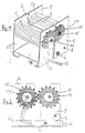
- a device comprises two parallel, toothed rollers 1, 1a, wherein a differently wide roller gap 2 can be set between the two rollers.
- the desired contact pressure of the rollers on the fresh meat is regulated by changing the width of the roller gap 2. If necessary, suspension devices are used accordingly.
- Both rollers are mounted in the corresponding side parts on both sides with slide bearings 20.
- a pair of side parts 22 is rigidly fixed to the base plate 4.
- the fixed roller 1 is supported on this pair of side parts 22.
- the passive roller 1 a arranged parallel to the fixed roller 1 is driven by the roller 1.
- a pair of side parts 5, between which the passive roller 1a is located, is movably attached to the base plate 4 by means of bearing bolts 6.
- a height inclination 21 of this pair of side parts 5 is achieved by eccentric rollers 7, which are attached to a continuous shaft 8.
- the side parts 5 are changed in parallel in their height inclination 21 via the eccentric rollers 7.
- Both rollers are each toothed only in the longitudinal direction of the roller 9.
- the toothing 10 of the rollers runs the same in accordance with their direction of rotation 13.
- a standard dimension of 0.8 - 4 mm is provided vertically as tooth depth 11. Smaller and larger tooth depths are also conceivable.
- a roller tooth to the next roller tooth 23 results in a 90 ° angle (plus or minus 5 ° deviation).
- the tooth surfaces can also be curved, which can be achieved by an appropriate shape of the milling tool for the roller.
- the roller teeth 10 detect the work to be machined by moving the rollers in opposite directions Fresh meat and move it in, as it were the effect of a harpoon the roll gap 2. This enables the rolling stock to be drawn in without any problems.
- the number of roller teeth per roller depends on the roller diameter selected. At z. B. 10cm roller diameter 12, the amount of teeth is about 20 - 25 pieces. Both rollers are moved in opposite directions to each other during the work process. 13.
- the roller teeth look against each other 10.
- the processed fresh meat is passed through the nip 2 "Walked through”. Through this operation, the structure of the fresh meat also loosened up or worn down.
- the advantage of the device according to the invention results in particular from the special design of the roller shape 1, 1a, 9, 10, 11, 13, 23.
- the axis 14 of the fixed roller 1 has a drive gear on the outside of the side wall 15. Via a connection / intermediate piece from the drive gear 15 the actual drive drives the device.
- the drive can both mechanically, e.g. B. with a crank 16, or electrically.
- the device On the axis 17 of the passive roller 1a sits on the same outside of the side wall 5 the device also a gear 18 which is driven by the drive gear becomes. The course of movement of both gears is therefore opposite in the direction of rotation.
- the entire device is attached to the underbody 19, e.g. B. via suction cups, Clamps, screws and similar fasteners.
- All materials used, from which the device is constructed, consists made of food-grade materials.
- the device can be easily dismantled and clean.
Landscapes
- Life Sciences & Earth Sciences (AREA)
- Engineering & Computer Science (AREA)
- Wood Science & Technology (AREA)
- Zoology (AREA)
- Food Science & Technology (AREA)
- Meat, Egg Or Seafood Products (AREA)
- Processing Of Meat And Fish (AREA)
- General Preparation And Processing Of Foods (AREA)
Abstract
Description
Beide Walzen sind in den entsprechenden Seitenteilen beidseitig mit Gleitlagern gelagert 20. Ein Seitenteilpaar 22 ist an der Bodenplatte 4 starr fixiert. An diesem Seitenteilpaar 22, ist die feste Walze 1 gelagert. Die parallel zur festen Walze 1 angeordnete passive Walze 1a wird über die Walze 1 angetrieben. Ein Seitenteilpaar 5, zwischen dem sich die passive Walze 1a befindet, ist beweglich durch Lagerbolzen 6 an der Bodenplatte 4 befestigt.
Ein Walzenzahn zum nächsten Walzenzahn 23 ergibt einen 90°-Winkel (plus oder minus 5° Abweichung). Die Zahnflächen können auch gewölbt sein, was durch eine entsprechende Form des Fräswerkzeugs für die Walze erreicht werden kann.
Claims (10)
- Fleischwalze (1, 1a) miteinem Walzenmantel in der Form eines Zylinders undeiner Vielzahl an Walzenzähnen (10) auf der Oberfläche des Walzenmantels, die sich im wesentlichen längs der Achse des Zylinders erstrecken,
dadurch gekennzeichnet, dassjeder der Vielzahl an Walzenzähnen (10) jeweils eine erste Fläche, die im wesentlichen auf einer Ebene durch die Achse des Zylinders liegt, und eine zweite Fläche, die im wesentlichen senkrecht (23) zu einer ersten Fläche eines benachbarten Walzenzahns angeordnet ist, aufweist. - Fleischwalze nach Anspruch 1, wobei die Vielzahl an Walzenzähnen (10) gleichmäßig am Umfang des Walzenmantels mit oder ohne Zwischenraum angeordnet ist.
- Fleischwalze nach Anspruch 1 oder 2, wobei sich die Walzenzähne (10) über die gesamte Mantellänge oder lediglich einen Teil davon erstrecken und die Walzenzähne vorzugsweise einteilig mit dem Walzenkörper sind.
- Fleischwalze nach Anspruch 1, 2 oder 3, wobei die Höhe (11) der Walzenzähne in radialer Richtung des Zylinders im Bereich von 0,8 bis 4 mm liegt.
- Vorrichtung zum Bearbeiten von Fleischstücken mit mindestens einer Fleischwalze (1, 1a) nach einem der Ansprüche 1 bis 4.
- Vorrichtung nach Anspruch 5 mit mindestens einem Paar an Fleischwalzen (1, 1a), die im wesentlichen parallel nebeneinander unter Bildung eines Walzenspalts (2) angeordnet und gegenläufig drehbar sind.
- Vorrichtung nach Anspruch 6, wobei die Fleischwalzen (1, 1a) des mindestens einen Paars an Fleischwalzen hinsichtlich der Walzenzähne (10) im wesentlichen identisch und antiparallel angeordnet sind.
- Vorrichtung nach einem der Ansprüche 5 bis 7, wobei der Anpressdruck der Walzen (1, 1a) bzw. Walzenzähne (10) auf das zu bearbeitende Fleisch durch Veränderung des Höhenwinkels (21) eines beweglichen Seitenteils (5), in dem eine der Walzen gelagert ist, mittels eines drehbar gelagerten Exzenters (7) regelbar ist.
- Vorrichtung nach einem der Ansprüche 6 bis 8, wobei jeweils mehrere Fleischwalzen auf jeder Achse des mindestens einen Walzenpaars angeordnet sind und/oder wobei mehrere Walzenpaare derart angeordnet sind, dass ein Fleischstück bei seiner Bearbeitung die mehreren Walzenpaare durchläuft.
- Vorrichtung nach einem der Ansprüche 6 bis 9, wobei die Walzen durch ein Getriebe untereinander verbunden sind.
Priority Applications (1)
| Application Number | Priority Date | Filing Date | Title |
|---|---|---|---|
| SI200030095T SI1090554T1 (en) | 1999-10-08 | 2000-10-04 | Device for treating meat |
Applications Claiming Priority (8)
| Application Number | Priority Date | Filing Date | Title |
|---|---|---|---|
| DE19948482 | 1999-10-08 | ||
| DE29917752U | 1999-10-08 | ||
| DE29917752U DE29917752U1 (de) | 1999-10-08 | 1999-10-08 | Vorrichtung zur Mürbung mit gleichzeitiger Flächenvergrößerung von Frischfleisch ohne Knochen im Lebensmittelbereich |
| DE19948482 | 1999-10-08 | ||
| DE20015545U | 2000-09-07 | ||
| DE20015545U DE20015545U1 (de) | 2000-09-07 | 2000-09-07 | Vorrichtung zur Mürbung mit gleichzeitiger Flächenvergrößerung von Frischfleisch ohne Knochenanteil im Lebensmittelbereich |
| DE10045444 | 2000-09-14 | ||
| DE10045444A DE10045444A1 (de) | 1999-10-08 | 2000-09-14 | Vorrichtung und entsprechendes Verfahren zur Mürbung mit gleichzeitiger Flächenvergrößerung von Frischfleisch ohne Knochenanteil im Lebensmittelbereich |
Publications (2)
| Publication Number | Publication Date |
|---|---|
| EP1090554A1 true EP1090554A1 (de) | 2001-04-11 |
| EP1090554B1 EP1090554B1 (de) | 2003-04-23 |
Family
ID=27437878
Family Applications (1)
| Application Number | Title | Priority Date | Filing Date |
|---|---|---|---|
| EP00121256A Expired - Lifetime EP1090554B1 (de) | 1999-10-08 | 2000-10-04 | Vorrichtung zur Bearbeitung von Fleisch |
Country Status (5)
| Country | Link |
|---|---|
| EP (1) | EP1090554B1 (de) |
| AT (1) | ATE237944T1 (de) |
| DK (1) | DK1090554T3 (de) |
| ES (1) | ES2197049T3 (de) |
| PT (1) | PT1090554E (de) |
Cited By (2)
| Publication number | Priority date | Publication date | Assignee | Title |
|---|---|---|---|---|
| WO2004054374A1 (de) * | 2002-12-18 | 2004-07-01 | Franz Kindermann | Fleischwalzenanordnung und verfahren zur bearbeitung von fleisch |
| CN108812831A (zh) * | 2018-07-20 | 2018-11-16 | 临泉县生产力促进中心 | 一种肉类加工用肉块滚揉装置 |
Citations (5)
| Publication number | Priority date | Publication date | Assignee | Title |
|---|---|---|---|---|
| DE3344284A1 (de) | 1983-12-07 | 1985-06-13 | Holac-Maschinenbau Gmbh, 7920 Heidenheim | Vorrichtung zur behandlung von fleisch oder schinken, insbesondere von kochpoekelwaren |
| US4531259A (en) * | 1983-10-31 | 1985-07-30 | Bridge Jr Edward W | Meat tenderizer apparatus |
| US4660252A (en) * | 1986-02-27 | 1987-04-28 | Hobart Corporation | Knife roll assembly for a meat tenderizer |
| EP0478221A1 (de) * | 1990-09-26 | 1992-04-01 | Oscar Mayer Foods Corporation | Vorrichtung zum Massieren von Fleisch |
| WO1994018842A1 (en) * | 1993-02-24 | 1994-09-01 | Juhring, Avery, B. | Apparatus and process for tenderizing meat |
-
2000
- 2000-10-04 AT AT00121256T patent/ATE237944T1/de active
- 2000-10-04 DK DK00121256T patent/DK1090554T3/da active
- 2000-10-04 ES ES00121256T patent/ES2197049T3/es not_active Expired - Lifetime
- 2000-10-04 EP EP00121256A patent/EP1090554B1/de not_active Expired - Lifetime
- 2000-10-04 PT PT00121256T patent/PT1090554E/pt unknown
Patent Citations (5)
| Publication number | Priority date | Publication date | Assignee | Title |
|---|---|---|---|---|
| US4531259A (en) * | 1983-10-31 | 1985-07-30 | Bridge Jr Edward W | Meat tenderizer apparatus |
| DE3344284A1 (de) | 1983-12-07 | 1985-06-13 | Holac-Maschinenbau Gmbh, 7920 Heidenheim | Vorrichtung zur behandlung von fleisch oder schinken, insbesondere von kochpoekelwaren |
| US4660252A (en) * | 1986-02-27 | 1987-04-28 | Hobart Corporation | Knife roll assembly for a meat tenderizer |
| EP0478221A1 (de) * | 1990-09-26 | 1992-04-01 | Oscar Mayer Foods Corporation | Vorrichtung zum Massieren von Fleisch |
| WO1994018842A1 (en) * | 1993-02-24 | 1994-09-01 | Juhring, Avery, B. | Apparatus and process for tenderizing meat |
Cited By (5)
| Publication number | Priority date | Publication date | Assignee | Title |
|---|---|---|---|---|
| WO2004054374A1 (de) * | 2002-12-18 | 2004-07-01 | Franz Kindermann | Fleischwalzenanordnung und verfahren zur bearbeitung von fleisch |
| US7070495B2 (en) | 2002-12-18 | 2006-07-04 | Franz Kindermann | Meat rolling device and method for treating meat |
| CZ300422B6 (cs) * | 2002-12-18 | 2009-05-13 | KINDERMANN@Franz | Zarízení pro válcování masa a zpusob zpracování masa |
| CN108812831A (zh) * | 2018-07-20 | 2018-11-16 | 临泉县生产力促进中心 | 一种肉类加工用肉块滚揉装置 |
| CN108812831B (zh) * | 2018-07-20 | 2020-06-05 | 漳州鑫阳食品有限公司 | 一种肉类加工用肉块滚揉装置 |
Also Published As
| Publication number | Publication date |
|---|---|
| EP1090554B1 (de) | 2003-04-23 |
| ES2197049T3 (es) | 2004-01-01 |
| PT1090554E (pt) | 2003-09-30 |
| DK1090554T3 (da) | 2003-08-11 |
| ATE237944T1 (de) | 2003-05-15 |
Similar Documents
| Publication | Publication Date | Title |
|---|---|---|
| EP0421991B1 (de) | Vorrichtung zur behandlung von fleisch | |
| DE2911322C2 (de) | Maschine zum Entgraten und Säubern von flächigen Werkstücken | |
| DE102006043972B4 (de) | Antriebsmechanismus und Schneidevorrichtung für Lebensmittelschneidemaschine | |
| DE69019660T2 (de) | Vorrichtung zum Ausbeinen von Fleischstücken. | |
| EP1578201B1 (de) | Fleischwalzenanordnung und verfahren zur bearbeitung von fleisch | |
| DE1809692A1 (de) | Verfahren und Vorrichtung zum fortlaufenden Abschneiden einzelner Frankfurter Wuerstchen von einer Kette dieser Wuerstchen | |
| DE2737957C2 (de) | Stangenzuführvorrichtung für Maschinen zum Verarbeiten rotierender Materialstangen | |
| WO2022184882A2 (de) | Aggregat zum entgraten und verrunden von kanten in einer flächenschleifmaschine | |
| DE69522000T2 (de) | Verfahren und vorrichtung zum schneiden von fisch | |
| DE2602152A1 (de) | Vorrichtung mit hohem sicherheitsgrad fuer die laermverminderung von zahnradverbindungen | |
| DE60314549T2 (de) | Maschine zur zartmachung | |
| EP1090554B1 (de) | Vorrichtung zur Bearbeitung von Fleisch | |
| DE3344284A1 (de) | Vorrichtung zur behandlung von fleisch oder schinken, insbesondere von kochpoekelwaren | |
| DE102013212885A1 (de) | Reinigungsvorrichtung | |
| DE3333175C1 (de) | Vorrichtung zum Reinigen von Glasplatten | |
| DE10120534B4 (de) | Fleischwalze mit Folie, Vorrichtung zum Bearbeiten von Fleischstücken und Verfahren zum Behandeln von Fleisch | |
| DE202021101316U1 (de) | Bearbeitungseinheit für eine Blechbearbeitungsmaschine | |
| DE10045444A1 (de) | Vorrichtung und entsprechendes Verfahren zur Mürbung mit gleichzeitiger Flächenvergrößerung von Frischfleisch ohne Knochenanteil im Lebensmittelbereich | |
| EP4132267A1 (de) | Vorrichtung und verfahren zum längsschneiden eines lebensmittelbandes, insbesondere eines käsebandes, in streifen | |
| DE3006832C2 (de) | Maschine zum Entgraten | |
| DE117327C (de) | Eine ununterbrochen arbeitende Ausstechmaschine für Biskuits. | |
| EP1542540B1 (de) | Vorrichtung zum plätten von lebensmitteln, insbesondere fleischstücken | |
| DE3837181C2 (de) | Enthäutungs- oder Abschwartmaschine | |
| DE2904079A1 (de) | Kontinuierlich arbeitende abfleischvorrichtung fuer haeute | |
| DE602005005521T2 (de) | Verfahren und vorrichtung zum entfernen von haut und fett von fleischteilen |
Legal Events
| Date | Code | Title | Description |
|---|---|---|---|
| PUAI | Public reference made under article 153(3) epc to a published international application that has entered the european phase |
Free format text: ORIGINAL CODE: 0009012 |
|
| AK | Designated contracting states |
Kind code of ref document: A1 Designated state(s): AT BE CH CY DE DK ES FI FR GB GR IE IT LI LU MC NL PT SE |
|
| AX | Request for extension of the european patent |
Free format text: AL;LT;LV;MK;RO;SI |
|
| AKX | Designation fees paid | ||
| 17P | Request for examination filed |
Effective date: 20010913 |
|
| RAX | Requested extension states of the european patent have changed |
Free format text: SI PAYMENT 20010913 |
|
| RBV | Designated contracting states (corrected) |
Designated state(s): AT BE CH CY DE DK ES FI FR GB GR IE IT LI LU MC NL PT SE |
|
| REG | Reference to a national code |
Ref country code: DE Ref legal event code: 8566 |
|
| 17Q | First examination report despatched |
Effective date: 20020701 |
|
| GRAH | Despatch of communication of intention to grant a patent |
Free format text: ORIGINAL CODE: EPIDOS IGRA |
|
| GRAH | Despatch of communication of intention to grant a patent |
Free format text: ORIGINAL CODE: EPIDOS IGRA |
|
| GRAA | (expected) grant |
Free format text: ORIGINAL CODE: 0009210 |
|
| AK | Designated contracting states |
Designated state(s): AT BE CH CY DE DK ES FI FR GB GR IE IT LI LU MC NL PT SE |
|
| AX | Request for extension of the european patent |
Extension state: SI |
|
| REG | Reference to a national code |
Ref country code: GB Ref legal event code: FG4D Free format text: NOT ENGLISH |
|
| REG | Reference to a national code |
Ref country code: CH Ref legal event code: EP |
|
| REF | Corresponds to: |
Ref document number: 50001846 Country of ref document: DE Date of ref document: 20030528 Kind code of ref document: P |
|
| REG | Reference to a national code |
Ref country code: IE Ref legal event code: FG4D Free format text: GERMAN |
|
| REG | Reference to a national code |
Ref country code: CH Ref legal event code: NV Representative=s name: PATENTANWAELTE BREITER + WIEDMER AG |
|
| PG25 | Lapsed in a contracting state [announced via postgrant information from national office to epo] |
Ref country code: GR Free format text: LAPSE BECAUSE OF FAILURE TO SUBMIT A TRANSLATION OF THE DESCRIPTION OR TO PAY THE FEE WITHIN THE PRESCRIBED TIME-LIMIT Effective date: 20030723 |
|
| REG | Reference to a national code |
Ref country code: SE Ref legal event code: TRGR |
|
| REG | Reference to a national code |
Ref country code: DK Ref legal event code: T3 |
|
| GBT | Gb: translation of ep patent filed (gb section 77(6)(a)/1977) | ||
| REG | Reference to a national code |
Ref country code: PT Ref legal event code: SC4A Free format text: AVAILABILITY OF NATIONAL TRANSLATION Effective date: 20030722 |
|
| PG25 | Lapsed in a contracting state [announced via postgrant information from national office to epo] |
Ref country code: CY Free format text: LAPSE BECAUSE OF FAILURE TO SUBMIT A TRANSLATION OF THE DESCRIPTION OR TO PAY THE FEE WITHIN THE PRESCRIBED TIME-LIMIT Effective date: 20031004 |
|
| PG25 | Lapsed in a contracting state [announced via postgrant information from national office to epo] |
Ref country code: MC Free format text: LAPSE BECAUSE OF NON-PAYMENT OF DUE FEES Effective date: 20031031 |
|
| REG | Reference to a national code |
Ref country code: ES Ref legal event code: FG2A Ref document number: 2197049 Country of ref document: ES Kind code of ref document: T3 |
|
| ET | Fr: translation filed | ||
| PLBE | No opposition filed within time limit |
Free format text: ORIGINAL CODE: 0009261 |
|
| STAA | Information on the status of an ep patent application or granted ep patent |
Free format text: STATUS: NO OPPOSITION FILED WITHIN TIME LIMIT |
|
| 26N | No opposition filed |
Effective date: 20040126 |
|
| REG | Reference to a national code |
Ref country code: SI Ref legal event code: IF |
|
| REG | Reference to a national code |
Ref country code: CH Ref legal event code: PFA Owner name: KINDERMANN, FRANZ Free format text: KINDERMANN, FRANZ#STRASS 2A#84329 WURMANNSQUICK (DE) -TRANSFER TO- KINDERMANN, FRANZ#STRASS 2A#84329 WURMANNSQUICK (DE) |
|
| PGFP | Annual fee paid to national office [announced via postgrant information from national office to epo] |
Ref country code: DK Payment date: 20131024 Year of fee payment: 14 |
|
| PGFP | Annual fee paid to national office [announced via postgrant information from national office to epo] |
Ref country code: FR Payment date: 20131018 Year of fee payment: 14 Ref country code: SE Payment date: 20131022 Year of fee payment: 14 Ref country code: GB Payment date: 20131022 Year of fee payment: 14 Ref country code: LU Payment date: 20131022 Year of fee payment: 14 Ref country code: IE Payment date: 20131018 Year of fee payment: 14 Ref country code: BE Payment date: 20131021 Year of fee payment: 14 Ref country code: PT Payment date: 20131024 Year of fee payment: 14 |
|
| PGFP | Annual fee paid to national office [announced via postgrant information from national office to epo] |
Ref country code: IT Payment date: 20131030 Year of fee payment: 14 Ref country code: FI Payment date: 20131021 Year of fee payment: 14 Ref country code: ES Payment date: 20131022 Year of fee payment: 14 |
|
| REG | Reference to a national code |
Ref country code: PT Ref legal event code: MM4A Free format text: LAPSE DUE TO NON-PAYMENT OF FEES Effective date: 20150406 |
|
| REG | Reference to a national code |
Ref country code: DK Ref legal event code: EBP Effective date: 20141031 |
|
| PG25 | Lapsed in a contracting state [announced via postgrant information from national office to epo] |
Ref country code: LU Free format text: LAPSE BECAUSE OF NON-PAYMENT OF DUE FEES Effective date: 20141004 |
|
| REG | Reference to a national code |
Ref country code: SE Ref legal event code: EUG |
|
| GBPC | Gb: european patent ceased through non-payment of renewal fee |
Effective date: 20141004 |
|
| PG25 | Lapsed in a contracting state [announced via postgrant information from national office to epo] |
Ref country code: BE Free format text: LAPSE BECAUSE OF NON-PAYMENT OF DUE FEES Effective date: 20141031 |
|
| REG | Reference to a national code |
Ref country code: IE Ref legal event code: MM4A |
|
| PG25 | Lapsed in a contracting state [announced via postgrant information from national office to epo] |
Ref country code: GB Free format text: LAPSE BECAUSE OF NON-PAYMENT OF DUE FEES Effective date: 20141004 Ref country code: SE Free format text: LAPSE BECAUSE OF NON-PAYMENT OF DUE FEES Effective date: 20141005 Ref country code: FI Free format text: LAPSE BECAUSE OF NON-PAYMENT OF DUE FEES Effective date: 20141004 Ref country code: PT Free format text: LAPSE BECAUSE OF NON-PAYMENT OF DUE FEES Effective date: 20150406 |
|
| REG | Reference to a national code |
Ref country code: FR Ref legal event code: ST Effective date: 20150630 Ref country code: SI Ref legal event code: KO00 Effective date: 20150610 |
|
| PG25 | Lapsed in a contracting state [announced via postgrant information from national office to epo] |
Ref country code: IT Free format text: LAPSE BECAUSE OF NON-PAYMENT OF DUE FEES Effective date: 20141004 Ref country code: FR Free format text: LAPSE BECAUSE OF NON-PAYMENT OF DUE FEES Effective date: 20141031 |
|
| PG25 | Lapsed in a contracting state [announced via postgrant information from national office to epo] |
Ref country code: IE Free format text: LAPSE BECAUSE OF NON-PAYMENT OF DUE FEES Effective date: 20141004 Ref country code: DK Free format text: LAPSE BECAUSE OF NON-PAYMENT OF DUE FEES Effective date: 20141031 |
|
| REG | Reference to a national code |
Ref country code: ES Ref legal event code: FD2A Effective date: 20151126 |
|
| PG25 | Lapsed in a contracting state [announced via postgrant information from national office to epo] |
Ref country code: ES Free format text: LAPSE BECAUSE OF NON-PAYMENT OF DUE FEES Effective date: 20141005 |
|
| PGFP | Annual fee paid to national office [announced via postgrant information from national office to epo] |
Ref country code: AT Payment date: 20171023 Year of fee payment: 18 Ref country code: NL Payment date: 20171023 Year of fee payment: 18 |
|
| REG | Reference to a national code |
Ref country code: NL Ref legal event code: MM Effective date: 20181101 |
|
| REG | Reference to a national code |
Ref country code: AT Ref legal event code: MM01 Ref document number: 237944 Country of ref document: AT Kind code of ref document: T Effective date: 20181004 |
|
| PG25 | Lapsed in a contracting state [announced via postgrant information from national office to epo] |
Ref country code: NL Free format text: LAPSE BECAUSE OF NON-PAYMENT OF DUE FEES Effective date: 20181101 |
|
| PGFP | Annual fee paid to national office [announced via postgrant information from national office to epo] |
Ref country code: DE Payment date: 20190402 Year of fee payment: 19 |
|
| PGFP | Annual fee paid to national office [announced via postgrant information from national office to epo] |
Ref country code: CH Payment date: 20190405 Year of fee payment: 19 |
|
| PG25 | Lapsed in a contracting state [announced via postgrant information from national office to epo] |
Ref country code: AT Free format text: LAPSE BECAUSE OF NON-PAYMENT OF DUE FEES Effective date: 20181004 |
|
| REG | Reference to a national code |
Ref country code: DE Ref legal event code: R119 Ref document number: 50001846 Country of ref document: DE |
|
| REG | Reference to a national code |
Ref country code: CH Ref legal event code: PL |
|
| PG25 | Lapsed in a contracting state [announced via postgrant information from national office to epo] |
Ref country code: DE Free format text: LAPSE BECAUSE OF NON-PAYMENT OF DUE FEES Effective date: 20200501 Ref country code: LI Free format text: LAPSE BECAUSE OF NON-PAYMENT OF DUE FEES Effective date: 20191031 Ref country code: CH Free format text: LAPSE BECAUSE OF NON-PAYMENT OF DUE FEES Effective date: 20191031 |