EP1089822B1 - Einrichtung für eine nahezu gleichzeitige synthese einer vielzahl von proben - Google Patents
Einrichtung für eine nahezu gleichzeitige synthese einer vielzahl von proben Download PDFInfo
- Publication number
- EP1089822B1 EP1089822B1 EP99927960A EP99927960A EP1089822B1 EP 1089822 B1 EP1089822 B1 EP 1089822B1 EP 99927960 A EP99927960 A EP 99927960A EP 99927960 A EP99927960 A EP 99927960A EP 1089822 B1 EP1089822 B1 EP 1089822B1
- Authority
- EP
- European Patent Office
- Prior art keywords
- cover
- barriers
- cavities
- support plate
- capillary
- Prior art date
- Legal status (The legal status is an assumption and is not a legal conclusion. Google has not performed a legal analysis and makes no representation as to the accuracy of the status listed.)
- Expired - Lifetime
Links
- 230000015572 biosynthetic process Effects 0.000 title claims abstract description 19
- 238000003786 synthesis reaction Methods 0.000 title claims abstract description 17
- 239000007788 liquid Substances 0.000 claims abstract description 48
- 239000011325 microbead Substances 0.000 claims abstract description 21
- 125000006850 spacer group Chemical group 0.000 claims description 2
- 230000004888 barrier function Effects 0.000 claims 8
- 230000002209 hydrophobic effect Effects 0.000 claims 1
- 238000007373 indentation Methods 0.000 claims 1
- 238000000034 method Methods 0.000 abstract description 5
- 239000000126 substance Substances 0.000 description 8
- 239000002245 particle Substances 0.000 description 7
- 238000006243 chemical reaction Methods 0.000 description 6
- 239000011521 glass Substances 0.000 description 6
- 239000011324 bead Substances 0.000 description 5
- 238000011049 filling Methods 0.000 description 5
- 238000005516 engineering process Methods 0.000 description 3
- 239000000463 material Substances 0.000 description 3
- 238000005086 pumping Methods 0.000 description 3
- 238000012549 training Methods 0.000 description 3
- 238000004140 cleaning Methods 0.000 description 2
- 230000008878 coupling Effects 0.000 description 2
- 238000010168 coupling process Methods 0.000 description 2
- 238000005859 coupling reaction Methods 0.000 description 2
- 238000006073 displacement reaction Methods 0.000 description 2
- 238000005429 filling process Methods 0.000 description 2
- 239000002184 metal Substances 0.000 description 2
- XLYOFNOQVPJJNP-UHFFFAOYSA-N water Substances O XLYOFNOQVPJJNP-UHFFFAOYSA-N 0.000 description 2
- 108091034117 Oligonucleotide Proteins 0.000 description 1
- JLCPHMBAVCMARE-UHFFFAOYSA-N [3-[[3-[[3-[[3-[[3-[[3-[[3-[[3-[[3-[[3-[[3-[[5-(2-amino-6-oxo-1H-purin-9-yl)-3-[[3-[[3-[[3-[[3-[[3-[[5-(2-amino-6-oxo-1H-purin-9-yl)-3-[[5-(2-amino-6-oxo-1H-purin-9-yl)-3-hydroxyoxolan-2-yl]methoxy-hydroxyphosphoryl]oxyoxolan-2-yl]methoxy-hydroxyphosphoryl]oxy-5-(5-methyl-2,4-dioxopyrimidin-1-yl)oxolan-2-yl]methoxy-hydroxyphosphoryl]oxy-5-(6-aminopurin-9-yl)oxolan-2-yl]methoxy-hydroxyphosphoryl]oxy-5-(6-aminopurin-9-yl)oxolan-2-yl]methoxy-hydroxyphosphoryl]oxy-5-(6-aminopurin-9-yl)oxolan-2-yl]methoxy-hydroxyphosphoryl]oxy-5-(6-aminopurin-9-yl)oxolan-2-yl]methoxy-hydroxyphosphoryl]oxyoxolan-2-yl]methoxy-hydroxyphosphoryl]oxy-5-(5-methyl-2,4-dioxopyrimidin-1-yl)oxolan-2-yl]methoxy-hydroxyphosphoryl]oxy-5-(4-amino-2-oxopyrimidin-1-yl)oxolan-2-yl]methoxy-hydroxyphosphoryl]oxy-5-(5-methyl-2,4-dioxopyrimidin-1-yl)oxolan-2-yl]methoxy-hydroxyphosphoryl]oxy-5-(5-methyl-2,4-dioxopyrimidin-1-yl)oxolan-2-yl]methoxy-hydroxyphosphoryl]oxy-5-(6-aminopurin-9-yl)oxolan-2-yl]methoxy-hydroxyphosphoryl]oxy-5-(6-aminopurin-9-yl)oxolan-2-yl]methoxy-hydroxyphosphoryl]oxy-5-(4-amino-2-oxopyrimidin-1-yl)oxolan-2-yl]methoxy-hydroxyphosphoryl]oxy-5-(4-amino-2-oxopyrimidin-1-yl)oxolan-2-yl]methoxy-hydroxyphosphoryl]oxy-5-(4-amino-2-oxopyrimidin-1-yl)oxolan-2-yl]methoxy-hydroxyphosphoryl]oxy-5-(6-aminopurin-9-yl)oxolan-2-yl]methoxy-hydroxyphosphoryl]oxy-5-(4-amino-2-oxopyrimidin-1-yl)oxolan-2-yl]methyl [5-(6-aminopurin-9-yl)-2-(hydroxymethyl)oxolan-3-yl] hydrogen phosphate Polymers Cc1cn(C2CC(OP(O)(=O)OCC3OC(CC3OP(O)(=O)OCC3OC(CC3O)n3cnc4c3nc(N)[nH]c4=O)n3cnc4c3nc(N)[nH]c4=O)C(COP(O)(=O)OC3CC(OC3COP(O)(=O)OC3CC(OC3COP(O)(=O)OC3CC(OC3COP(O)(=O)OC3CC(OC3COP(O)(=O)OC3CC(OC3COP(O)(=O)OC3CC(OC3COP(O)(=O)OC3CC(OC3COP(O)(=O)OC3CC(OC3COP(O)(=O)OC3CC(OC3COP(O)(=O)OC3CC(OC3COP(O)(=O)OC3CC(OC3COP(O)(=O)OC3CC(OC3COP(O)(=O)OC3CC(OC3COP(O)(=O)OC3CC(OC3COP(O)(=O)OC3CC(OC3COP(O)(=O)OC3CC(OC3COP(O)(=O)OC3CC(OC3CO)n3cnc4c(N)ncnc34)n3ccc(N)nc3=O)n3cnc4c(N)ncnc34)n3ccc(N)nc3=O)n3ccc(N)nc3=O)n3ccc(N)nc3=O)n3cnc4c(N)ncnc34)n3cnc4c(N)ncnc34)n3cc(C)c(=O)[nH]c3=O)n3cc(C)c(=O)[nH]c3=O)n3ccc(N)nc3=O)n3cc(C)c(=O)[nH]c3=O)n3cnc4c3nc(N)[nH]c4=O)n3cnc4c(N)ncnc34)n3cnc4c(N)ncnc34)n3cnc4c(N)ncnc34)n3cnc4c(N)ncnc34)O2)c(=O)[nH]c1=O JLCPHMBAVCMARE-UHFFFAOYSA-N 0.000 description 1
- 230000006978 adaptation Effects 0.000 description 1
- 238000003491 array Methods 0.000 description 1
- 239000005352 borofloat Substances 0.000 description 1
- 230000004858 capillary barrier Effects 0.000 description 1
- 239000000969 carrier Substances 0.000 description 1
- 239000011248 coating agent Substances 0.000 description 1
- 238000000576 coating method Methods 0.000 description 1
- 238000004440 column chromatography Methods 0.000 description 1
- 238000013461 design Methods 0.000 description 1
- 229910003460 diamond Inorganic materials 0.000 description 1
- 239000010432 diamond Substances 0.000 description 1
- 238000009826 distribution Methods 0.000 description 1
- 238000005553 drilling Methods 0.000 description 1
- 238000001704 evaporation Methods 0.000 description 1
- 230000008020 evaporation Effects 0.000 description 1
- 238000000605 extraction Methods 0.000 description 1
- 238000002523 gelfiltration Methods 0.000 description 1
- 230000005660 hydrophilic surface Effects 0.000 description 1
- 230000005661 hydrophobic surface Effects 0.000 description 1
- 230000002706 hydrostatic effect Effects 0.000 description 1
- 238000002955 isolation Methods 0.000 description 1
- 238000011005 laboratory method Methods 0.000 description 1
- 238000003754 machining Methods 0.000 description 1
- 238000002156 mixing Methods 0.000 description 1
- 238000010422 painting Methods 0.000 description 1
- 229920000642 polymer Polymers 0.000 description 1
- 239000002952 polymeric resin Substances 0.000 description 1
- 239000011148 porous material Substances 0.000 description 1
- 102000004196 processed proteins & peptides Human genes 0.000 description 1
- 108090000765 processed proteins & peptides Proteins 0.000 description 1
- 238000012545 processing Methods 0.000 description 1
- 239000012487 rinsing solution Substances 0.000 description 1
- 238000000926 separation method Methods 0.000 description 1
- 239000007790 solid phase Substances 0.000 description 1
- 238000010532 solid phase synthesis reaction Methods 0.000 description 1
- 239000000243 solution Substances 0.000 description 1
- 238000001179 sorption measurement Methods 0.000 description 1
- 229920003002 synthetic resin Polymers 0.000 description 1
- 238000012546 transfer Methods 0.000 description 1
- 239000012780 transparent material Substances 0.000 description 1
- 238000011144 upstream manufacturing Methods 0.000 description 1
Images


Classifications
-
- B—PERFORMING OPERATIONS; TRANSPORTING
- B01—PHYSICAL OR CHEMICAL PROCESSES OR APPARATUS IN GENERAL
- B01J—CHEMICAL OR PHYSICAL PROCESSES, e.g. CATALYSIS OR COLLOID CHEMISTRY; THEIR RELEVANT APPARATUS
- B01J19/00—Chemical, physical or physico-chemical processes in general; Their relevant apparatus
- B01J19/0046—Sequential or parallel reactions, e.g. for the synthesis of polypeptides or polynucleotides; Apparatus and devices for combinatorial chemistry or for making molecular arrays
-
- B—PERFORMING OPERATIONS; TRANSPORTING
- B01—PHYSICAL OR CHEMICAL PROCESSES OR APPARATUS IN GENERAL
- B01L—CHEMICAL OR PHYSICAL LABORATORY APPARATUS FOR GENERAL USE
- B01L3/00—Containers or dishes for laboratory use, e.g. laboratory glassware; Droppers
- B01L3/02—Burettes; Pipettes
- B01L3/0289—Apparatus for withdrawing or distributing predetermined quantities of fluid
- B01L3/0293—Apparatus for withdrawing or distributing predetermined quantities of fluid for liquids
-
- B—PERFORMING OPERATIONS; TRANSPORTING
- B01—PHYSICAL OR CHEMICAL PROCESSES OR APPARATUS IN GENERAL
- B01L—CHEMICAL OR PHYSICAL LABORATORY APPARATUS FOR GENERAL USE
- B01L3/00—Containers or dishes for laboratory use, e.g. laboratory glassware; Droppers
- B01L3/50—Containers for the purpose of retaining a material to be analysed, e.g. test tubes
- B01L3/502—Containers for the purpose of retaining a material to be analysed, e.g. test tubes with fluid transport, e.g. in multi-compartment structures
- B01L3/5027—Containers for the purpose of retaining a material to be analysed, e.g. test tubes with fluid transport, e.g. in multi-compartment structures by integrated microfluidic structures, i.e. dimensions of channels and chambers are such that surface tension forces are important, e.g. lab-on-a-chip
-
- B—PERFORMING OPERATIONS; TRANSPORTING
- B01—PHYSICAL OR CHEMICAL PROCESSES OR APPARATUS IN GENERAL
- B01J—CHEMICAL OR PHYSICAL PROCESSES, e.g. CATALYSIS OR COLLOID CHEMISTRY; THEIR RELEVANT APPARATUS
- B01J2219/00—Chemical, physical or physico-chemical processes in general; Their relevant apparatus
- B01J2219/00274—Sequential or parallel reactions; Apparatus and devices for combinatorial chemistry or for making arrays; Chemical library technology
- B01J2219/00277—Apparatus
- B01J2219/00351—Means for dispensing and evacuation of reagents
- B01J2219/00364—Pipettes
- B01J2219/00367—Pipettes capillary
- B01J2219/00369—Pipettes capillary in multiple or parallel arrangements
-
- B—PERFORMING OPERATIONS; TRANSPORTING
- B01—PHYSICAL OR CHEMICAL PROCESSES OR APPARATUS IN GENERAL
- B01J—CHEMICAL OR PHYSICAL PROCESSES, e.g. CATALYSIS OR COLLOID CHEMISTRY; THEIR RELEVANT APPARATUS
- B01J2219/00—Chemical, physical or physico-chemical processes in general; Their relevant apparatus
- B01J2219/00274—Sequential or parallel reactions; Apparatus and devices for combinatorial chemistry or for making arrays; Chemical library technology
- B01J2219/00277—Apparatus
- B01J2219/00351—Means for dispensing and evacuation of reagents
- B01J2219/00427—Means for dispensing and evacuation of reagents using masks
-
- B—PERFORMING OPERATIONS; TRANSPORTING
- B01—PHYSICAL OR CHEMICAL PROCESSES OR APPARATUS IN GENERAL
- B01J—CHEMICAL OR PHYSICAL PROCESSES, e.g. CATALYSIS OR COLLOID CHEMISTRY; THEIR RELEVANT APPARATUS
- B01J2219/00—Chemical, physical or physico-chemical processes in general; Their relevant apparatus
- B01J2219/00274—Sequential or parallel reactions; Apparatus and devices for combinatorial chemistry or for making arrays; Chemical library technology
- B01J2219/00277—Apparatus
- B01J2219/00351—Means for dispensing and evacuation of reagents
- B01J2219/00427—Means for dispensing and evacuation of reagents using masks
- B01J2219/0043—Means for dispensing and evacuation of reagents using masks for direct application of reagents, e.g. through openings in a shutter
-
- B—PERFORMING OPERATIONS; TRANSPORTING
- B01—PHYSICAL OR CHEMICAL PROCESSES OR APPARATUS IN GENERAL
- B01J—CHEMICAL OR PHYSICAL PROCESSES, e.g. CATALYSIS OR COLLOID CHEMISTRY; THEIR RELEVANT APPARATUS
- B01J2219/00—Chemical, physical or physico-chemical processes in general; Their relevant apparatus
- B01J2219/00274—Sequential or parallel reactions; Apparatus and devices for combinatorial chemistry or for making arrays; Chemical library technology
- B01J2219/00277—Apparatus
- B01J2219/00457—Dispensing or evacuation of the solid phase support
- B01J2219/00459—Beads
- B01J2219/00468—Beads by manipulation of individual beads
-
- B—PERFORMING OPERATIONS; TRANSPORTING
- B01—PHYSICAL OR CHEMICAL PROCESSES OR APPARATUS IN GENERAL
- B01J—CHEMICAL OR PHYSICAL PROCESSES, e.g. CATALYSIS OR COLLOID CHEMISTRY; THEIR RELEVANT APPARATUS
- B01J2219/00—Chemical, physical or physico-chemical processes in general; Their relevant apparatus
- B01J2219/00274—Sequential or parallel reactions; Apparatus and devices for combinatorial chemistry or for making arrays; Chemical library technology
- B01J2219/00277—Apparatus
- B01J2219/00497—Features relating to the solid phase supports
- B01J2219/00527—Sheets
-
- B—PERFORMING OPERATIONS; TRANSPORTING
- B01—PHYSICAL OR CHEMICAL PROCESSES OR APPARATUS IN GENERAL
- B01J—CHEMICAL OR PHYSICAL PROCESSES, e.g. CATALYSIS OR COLLOID CHEMISTRY; THEIR RELEVANT APPARATUS
- B01J2219/00—Chemical, physical or physico-chemical processes in general; Their relevant apparatus
- B01J2219/00274—Sequential or parallel reactions; Apparatus and devices for combinatorial chemistry or for making arrays; Chemical library technology
- B01J2219/00583—Features relative to the processes being carried out
- B01J2219/00585—Parallel processes
-
- B—PERFORMING OPERATIONS; TRANSPORTING
- B01—PHYSICAL OR CHEMICAL PROCESSES OR APPARATUS IN GENERAL
- B01J—CHEMICAL OR PHYSICAL PROCESSES, e.g. CATALYSIS OR COLLOID CHEMISTRY; THEIR RELEVANT APPARATUS
- B01J2219/00—Chemical, physical or physico-chemical processes in general; Their relevant apparatus
- B01J2219/00274—Sequential or parallel reactions; Apparatus and devices for combinatorial chemistry or for making arrays; Chemical library technology
- B01J2219/00583—Features relative to the processes being carried out
- B01J2219/0059—Sequential processes
-
- B—PERFORMING OPERATIONS; TRANSPORTING
- B01—PHYSICAL OR CHEMICAL PROCESSES OR APPARATUS IN GENERAL
- B01J—CHEMICAL OR PHYSICAL PROCESSES, e.g. CATALYSIS OR COLLOID CHEMISTRY; THEIR RELEVANT APPARATUS
- B01J2219/00—Chemical, physical or physico-chemical processes in general; Their relevant apparatus
- B01J2219/00274—Sequential or parallel reactions; Apparatus and devices for combinatorial chemistry or for making arrays; Chemical library technology
- B01J2219/00583—Features relative to the processes being carried out
- B01J2219/00596—Solid-phase processes
-
- B—PERFORMING OPERATIONS; TRANSPORTING
- B01—PHYSICAL OR CHEMICAL PROCESSES OR APPARATUS IN GENERAL
- B01J—CHEMICAL OR PHYSICAL PROCESSES, e.g. CATALYSIS OR COLLOID CHEMISTRY; THEIR RELEVANT APPARATUS
- B01J2219/00—Chemical, physical or physico-chemical processes in general; Their relevant apparatus
- B01J2219/00274—Sequential or parallel reactions; Apparatus and devices for combinatorial chemistry or for making arrays; Chemical library technology
- B01J2219/00583—Features relative to the processes being carried out
- B01J2219/00603—Making arrays on substantially continuous surfaces
- B01J2219/00605—Making arrays on substantially continuous surfaces the compounds being directly bound or immobilised to solid supports
-
- B—PERFORMING OPERATIONS; TRANSPORTING
- B01—PHYSICAL OR CHEMICAL PROCESSES OR APPARATUS IN GENERAL
- B01J—CHEMICAL OR PHYSICAL PROCESSES, e.g. CATALYSIS OR COLLOID CHEMISTRY; THEIR RELEVANT APPARATUS
- B01J2219/00—Chemical, physical or physico-chemical processes in general; Their relevant apparatus
- B01J2219/00274—Sequential or parallel reactions; Apparatus and devices for combinatorial chemistry or for making arrays; Chemical library technology
- B01J2219/00583—Features relative to the processes being carried out
- B01J2219/00603—Making arrays on substantially continuous surfaces
- B01J2219/00605—Making arrays on substantially continuous surfaces the compounds being directly bound or immobilised to solid supports
- B01J2219/00612—Making arrays on substantially continuous surfaces the compounds being directly bound or immobilised to solid supports the surface being inorganic
-
- B—PERFORMING OPERATIONS; TRANSPORTING
- B01—PHYSICAL OR CHEMICAL PROCESSES OR APPARATUS IN GENERAL
- B01J—CHEMICAL OR PHYSICAL PROCESSES, e.g. CATALYSIS OR COLLOID CHEMISTRY; THEIR RELEVANT APPARATUS
- B01J2219/00—Chemical, physical or physico-chemical processes in general; Their relevant apparatus
- B01J2219/00274—Sequential or parallel reactions; Apparatus and devices for combinatorial chemistry or for making arrays; Chemical library technology
- B01J2219/00583—Features relative to the processes being carried out
- B01J2219/00603—Making arrays on substantially continuous surfaces
- B01J2219/00605—Making arrays on substantially continuous surfaces the compounds being directly bound or immobilised to solid supports
- B01J2219/00614—Delimitation of the attachment areas
- B01J2219/00617—Delimitation of the attachment areas by chemical means
- B01J2219/00619—Delimitation of the attachment areas by chemical means using hydrophilic or hydrophobic regions
-
- B—PERFORMING OPERATIONS; TRANSPORTING
- B01—PHYSICAL OR CHEMICAL PROCESSES OR APPARATUS IN GENERAL
- B01J—CHEMICAL OR PHYSICAL PROCESSES, e.g. CATALYSIS OR COLLOID CHEMISTRY; THEIR RELEVANT APPARATUS
- B01J2219/00—Chemical, physical or physico-chemical processes in general; Their relevant apparatus
- B01J2219/00274—Sequential or parallel reactions; Apparatus and devices for combinatorial chemistry or for making arrays; Chemical library technology
- B01J2219/00583—Features relative to the processes being carried out
- B01J2219/00603—Making arrays on substantially continuous surfaces
- B01J2219/00605—Making arrays on substantially continuous surfaces the compounds being directly bound or immobilised to solid supports
- B01J2219/00614—Delimitation of the attachment areas
- B01J2219/00621—Delimitation of the attachment areas by physical means, e.g. trenches, raised areas
-
- B—PERFORMING OPERATIONS; TRANSPORTING
- B01—PHYSICAL OR CHEMICAL PROCESSES OR APPARATUS IN GENERAL
- B01J—CHEMICAL OR PHYSICAL PROCESSES, e.g. CATALYSIS OR COLLOID CHEMISTRY; THEIR RELEVANT APPARATUS
- B01J2219/00—Chemical, physical or physico-chemical processes in general; Their relevant apparatus
- B01J2219/00274—Sequential or parallel reactions; Apparatus and devices for combinatorial chemistry or for making arrays; Chemical library technology
- B01J2219/00583—Features relative to the processes being carried out
- B01J2219/00603—Making arrays on substantially continuous surfaces
- B01J2219/00605—Making arrays on substantially continuous surfaces the compounds being directly bound or immobilised to solid supports
- B01J2219/00623—Immobilisation or binding
- B01J2219/0063—Other, e.g. van der Waals forces, hydrogen bonding
-
- B—PERFORMING OPERATIONS; TRANSPORTING
- B01—PHYSICAL OR CHEMICAL PROCESSES OR APPARATUS IN GENERAL
- B01J—CHEMICAL OR PHYSICAL PROCESSES, e.g. CATALYSIS OR COLLOID CHEMISTRY; THEIR RELEVANT APPARATUS
- B01J2219/00—Chemical, physical or physico-chemical processes in general; Their relevant apparatus
- B01J2219/00274—Sequential or parallel reactions; Apparatus and devices for combinatorial chemistry or for making arrays; Chemical library technology
- B01J2219/00583—Features relative to the processes being carried out
- B01J2219/00603—Making arrays on substantially continuous surfaces
- B01J2219/00605—Making arrays on substantially continuous surfaces the compounds being directly bound or immobilised to solid supports
- B01J2219/00632—Introduction of reactive groups to the surface
- B01J2219/00637—Introduction of reactive groups to the surface by coating it with another layer
-
- B—PERFORMING OPERATIONS; TRANSPORTING
- B01—PHYSICAL OR CHEMICAL PROCESSES OR APPARATUS IN GENERAL
- B01J—CHEMICAL OR PHYSICAL PROCESSES, e.g. CATALYSIS OR COLLOID CHEMISTRY; THEIR RELEVANT APPARATUS
- B01J2219/00—Chemical, physical or physico-chemical processes in general; Their relevant apparatus
- B01J2219/00274—Sequential or parallel reactions; Apparatus and devices for combinatorial chemistry or for making arrays; Chemical library technology
- B01J2219/00583—Features relative to the processes being carried out
- B01J2219/00603—Making arrays on substantially continuous surfaces
- B01J2219/00659—Two-dimensional arrays
-
- B—PERFORMING OPERATIONS; TRANSPORTING
- B01—PHYSICAL OR CHEMICAL PROCESSES OR APPARATUS IN GENERAL
- B01L—CHEMICAL OR PHYSICAL LABORATORY APPARATUS FOR GENERAL USE
- B01L2300/00—Additional constructional details
- B01L2300/06—Auxiliary integrated devices, integrated components
- B01L2300/0627—Sensor or part of a sensor is integrated
- B01L2300/0636—Integrated biosensor, microarrays
-
- B—PERFORMING OPERATIONS; TRANSPORTING
- B01—PHYSICAL OR CHEMICAL PROCESSES OR APPARATUS IN GENERAL
- B01L—CHEMICAL OR PHYSICAL LABORATORY APPARATUS FOR GENERAL USE
- B01L2300/00—Additional constructional details
- B01L2300/08—Geometry, shape and general structure
- B01L2300/0809—Geometry, shape and general structure rectangular shaped
- B01L2300/0819—Microarrays; Biochips
-
- B—PERFORMING OPERATIONS; TRANSPORTING
- B01—PHYSICAL OR CHEMICAL PROCESSES OR APPARATUS IN GENERAL
- B01L—CHEMICAL OR PHYSICAL LABORATORY APPARATUS FOR GENERAL USE
- B01L2300/00—Additional constructional details
- B01L2300/08—Geometry, shape and general structure
- B01L2300/089—Virtual walls for guiding liquids
-
- B—PERFORMING OPERATIONS; TRANSPORTING
- B01—PHYSICAL OR CHEMICAL PROCESSES OR APPARATUS IN GENERAL
- B01L—CHEMICAL OR PHYSICAL LABORATORY APPARATUS FOR GENERAL USE
- B01L2400/00—Moving or stopping fluids
- B01L2400/04—Moving fluids with specific forces or mechanical means
- B01L2400/0403—Moving fluids with specific forces or mechanical means specific forces
- B01L2400/0406—Moving fluids with specific forces or mechanical means specific forces capillary forces
-
- B—PERFORMING OPERATIONS; TRANSPORTING
- B01—PHYSICAL OR CHEMICAL PROCESSES OR APPARATUS IN GENERAL
- B01L—CHEMICAL OR PHYSICAL LABORATORY APPARATUS FOR GENERAL USE
- B01L3/00—Containers or dishes for laboratory use, e.g. laboratory glassware; Droppers
- B01L3/50—Containers for the purpose of retaining a material to be analysed, e.g. test tubes
- B01L3/502—Containers for the purpose of retaining a material to be analysed, e.g. test tubes with fluid transport, e.g. in multi-compartment structures
- B01L3/5027—Containers for the purpose of retaining a material to be analysed, e.g. test tubes with fluid transport, e.g. in multi-compartment structures by integrated microfluidic structures, i.e. dimensions of channels and chambers are such that surface tension forces are important, e.g. lab-on-a-chip
- B01L3/502715—Containers for the purpose of retaining a material to be analysed, e.g. test tubes with fluid transport, e.g. in multi-compartment structures by integrated microfluidic structures, i.e. dimensions of channels and chambers are such that surface tension forces are important, e.g. lab-on-a-chip characterised by interfacing components, e.g. fluidic, electrical, optical or mechanical interfaces
-
- B—PERFORMING OPERATIONS; TRANSPORTING
- B01—PHYSICAL OR CHEMICAL PROCESSES OR APPARATUS IN GENERAL
- B01L—CHEMICAL OR PHYSICAL LABORATORY APPARATUS FOR GENERAL USE
- B01L3/00—Containers or dishes for laboratory use, e.g. laboratory glassware; Droppers
- B01L3/50—Containers for the purpose of retaining a material to be analysed, e.g. test tubes
- B01L3/502—Containers for the purpose of retaining a material to be analysed, e.g. test tubes with fluid transport, e.g. in multi-compartment structures
- B01L3/5027—Containers for the purpose of retaining a material to be analysed, e.g. test tubes with fluid transport, e.g. in multi-compartment structures by integrated microfluidic structures, i.e. dimensions of channels and chambers are such that surface tension forces are important, e.g. lab-on-a-chip
- B01L3/50273—Containers for the purpose of retaining a material to be analysed, e.g. test tubes with fluid transport, e.g. in multi-compartment structures by integrated microfluidic structures, i.e. dimensions of channels and chambers are such that surface tension forces are important, e.g. lab-on-a-chip characterised by the means or forces applied to move the fluids
-
- C—CHEMISTRY; METALLURGY
- C40—COMBINATORIAL TECHNOLOGY
- C40B—COMBINATORIAL CHEMISTRY; LIBRARIES, e.g. CHEMICAL LIBRARIES
- C40B60/00—Apparatus specially adapted for use in combinatorial chemistry or with libraries
- C40B60/14—Apparatus specially adapted for use in combinatorial chemistry or with libraries for creating libraries
-
- G—PHYSICS
- G01—MEASURING; TESTING
- G01N—INVESTIGATING OR ANALYSING MATERIALS BY DETERMINING THEIR CHEMICAL OR PHYSICAL PROPERTIES
- G01N35/00—Automatic analysis not limited to methods or materials provided for in any single one of groups G01N1/00 - G01N33/00; Handling materials therefor
- G01N2035/00178—Special arrangements of analysers
- G01N2035/00237—Handling microquantities of analyte, e.g. microvalves, capillary networks
-
- Y—GENERAL TAGGING OF NEW TECHNOLOGICAL DEVELOPMENTS; GENERAL TAGGING OF CROSS-SECTIONAL TECHNOLOGIES SPANNING OVER SEVERAL SECTIONS OF THE IPC; TECHNICAL SUBJECTS COVERED BY FORMER USPC CROSS-REFERENCE ART COLLECTIONS [XRACs] AND DIGESTS
- Y10—TECHNICAL SUBJECTS COVERED BY FORMER USPC
- Y10T—TECHNICAL SUBJECTS COVERED BY FORMER US CLASSIFICATION
- Y10T436/00—Chemistry: analytical and immunological testing
- Y10T436/25—Chemistry: analytical and immunological testing including sample preparation
-
- Y—GENERAL TAGGING OF NEW TECHNOLOGICAL DEVELOPMENTS; GENERAL TAGGING OF CROSS-SECTIONAL TECHNOLOGIES SPANNING OVER SEVERAL SECTIONS OF THE IPC; TECHNICAL SUBJECTS COVERED BY FORMER USPC CROSS-REFERENCE ART COLLECTIONS [XRACs] AND DIGESTS
- Y10—TECHNICAL SUBJECTS COVERED BY FORMER USPC
- Y10T—TECHNICAL SUBJECTS COVERED BY FORMER US CLASSIFICATION
- Y10T436/00—Chemistry: analytical and immunological testing
- Y10T436/25—Chemistry: analytical and immunological testing including sample preparation
- Y10T436/2575—Volumetric liquid transfer
Definitions
- the invention relates to a device for an almost simultaneous Synthesis of a large number of samples, which in particular in automated laboratory operation in the field of combinatorial chemistry used.
- Sample particles (“Perlen”, “Beads”) have been used for decades Separation and synthesis used in the laboratory area. Usually, these are glass or polymer beads, which Diameters from 0.01 mm to 1 mm, typically around 0.1 mm, own and dry or pre-swollen as loose bulk in one Containers are filled and then rinsed with liquid, whereby between the solid phase surface of the particles and the surrounding one Liquid an adsorption or reaction process takes place.
- Procedure of Column chromatography e.g. gel filtration
- the column extraction the Immunodiagnostics
- biomolecule cleaning e.g. DNA cleaning
- homogeneous and heterogeneous synthesis of oligonucleotides, Peptides or combinatorial substance libraries
- samples are often placed in a grid arranged so that the identity (origin, nature) of the sample with a surface coordinate can be linked. These coordinates are especially easy for automated systems for sample processing to capture. So-called microtiter plates are therefore used for liquid samples have been developed which cavities in rectangular arrangements of Wear 8 x 12 (96 samples), 16 x 24 (384) or 32 x 48 (1536).
- the dimensions of the cavities of these sample carriers are based on this those that can be reliably dosed with standard devices (pipettes) Volumes and are subject to the advancement of dosing technology continuous miniaturization by whatever Aliquotability (division of a mother sample into different Daughter samples) of liquids is simplified.
- WO 98/24543 A1 describes a device for transferring liquids in which, among other things, a microtiter plate is provided, the chambers of which have at least one opening in the bottom area which is dimensioned in such a way that, during a filling process, the passage of liquid through this opening is avoided by means of capillary forces
- WO 98/06490 A1 describes an apparatus for an organic solid phase synthesis, in which the reaction vessel is arranged above a collecting vessel for receiving liquid in such a way that the transfer of the liquid can be achieved by generating a negative pressure. By contrast, the liquid is kept in the reaction vessel by a slight overpressure.
- a device for addressable combinatorial substance libraries is known from WO 97/19749 A1, in which a substance is represented in each case in a capillary tube, the filling with liquid being carried out by capillary forces.
- WO 97/37755 A1 describes a plate which contains a multiplicity of reaction cells which are arranged in rows and columns and which are supplied with liquid by pumps.
- the documents WO97 / 43629A1 and WO 98/16315 A1 describe liquid distribution systems which consist of a plurality of plates, the liquid flow being controlled and monitored by a capillary barrier or by electrokinetic pumping.
- the invention has for its object a device for almost simultaneous synthesis of a large number of samples that are bound on microbeads which are present in the cavities of a carrier plate, specify.
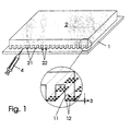
- a carrier plate 1 is assumed in FIG. 1, in which 11 microbeads 12 are provided in each case in individual cavities in such a way that they protrude beyond the cavity.
- microbeads with a diameter of 100 ⁇ m, they protrude from 20 to 50 ⁇ m from the surface of the carrier plate 1 in the sorted state.
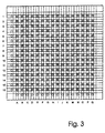
- 9 such microbeads each belong to a sample receiving area, with all sample receiving areas being aligned with one another in rows and columns (cf. FIG. 3).
- a removable cover 2 which, as the most important elements, carries webs 21 which are designed in their web width and length such that they cover all sample receiving areas of a row or column when placed on the carrier plate 1.
- a capillary gap 3 of predeterminable height and the predetermined width of the webs 21 of defined width are created by the protruding of the microbeads 12 in a defined manner.
- such a capillary gap can also be formed in that the carrier plate 1 in the region of the support of the webs 21 and / or the webs 21 themselves are provided with spacers of a defined height ,
- the webs 21 are spaced apart from one another by larger recesses 22 which are dimensioned such that no capillary forces act in them.
- the height of the capillary gap 3, at which capillary forces still act to transport liquids, depends on the surface tension of the materials for the carrier plate 1 and the webs 21 and the liquid used.
- the capillary forces act up to gap heights of 500 ⁇ m.
- the webs 21 can be provided with a hydrophilic or hydrophobic surface in the area of their support on the carrier plate, with at least the side walls of the recesses 22 delimiting the webs being provided with an oppositely acting surface coating.
- the capillary gap formed by the protruding microbeads 12 in the example opens up the possibility of specifically allowing liquids to flow along the gap.
- a structured cover plate is used, which has parallel recesses 22.
- the recesses 22 separate two parallel capillary gaps.
- the capillary gaps can be filled by pipetting liquid onto the end face of the cover, in each case at the beginning of a gap, as is schematically indicated in FIG. 1 by means of a gap by means of a meterable liquid dispenser 4. In order to fill each capillary gap with a different liquid, this requires very careful pipetting of the liquids in order to prevent the mixing of two liquids.
- a hose-like connections 5 or adapter pieces connected to these bores are used to connect to liquid reservoirs, for example a syringe pump, which are not shown in the following and are each assigned to a row or column, advantageously providing all of the liquid reservoirs with a uniformly defined pressure.
- Such connections can now be used to introduce liquids into the capillary gaps in a well-dosed manner.
- the pumping rate of the syringe pump must be adapted very precisely to the flow rate of the liquid, driven by the capillary forces, which can be determined experimentally in individual cases in order to avoid crosstalk of the liquid from one capillary gap to the next.
- the holes for the connection of hoses are to be made in the cover plate, in the center of the webs 21.
- Such an embodiment also makes it possible to provide an adapter for a microtiter plate instead of hose connections and to fill the capillary gaps by utilizing hydrostatic pressure differences.
- Figure 2a shows an embodiment of the device of FIG. 1 in a front side view, here is the support plate 1 with holes 13 provided, of which only five are shown in Fig. 2a, to which join hose-like connections 5 to the not shown Guide liquid reservoirs 4.
- the carrier plate 1 is in turn from one Displacement table V included a lateral displacement in parallel to the sheet normal.
- the carrier plate 1 and the cover 2 are still connected to each other by means of a guide 6.
- a such training enables the inclusion of a further developed Cover 2, as shown in Fig. 2b in plan view.
- the cover 2 further includes one porous section 23, which is followed by a planar section 24 is, which is dimensioned in such a way that it covers the entire Carrier plate 1 to form one that covers all sample areas Capillary gap can cover if this coverage area is moved over the support plate 1.
- the complete training of a such cover alone is shown in Fig. 4, with an alternative there the holes 25 are assigned to the first part of the cover 2.
- the procedure described for the actual synthesis of the desired samples is as follows:
- Carrier plate 1 and cover 2 are aligned with one another by means of an adjusting device (not shown in more detail), so that in each case a projecting web 21 rests on a row with pearl-filled reaction chambers.
- the webs 21 connect, for example, a row with 96 sample fields which carry 864 microbeads 12.
- the carrier plate also has two 96 through bores 13, which lie in the extension of the rows and columns of the pearl arrays.
- the hoses 5 described are attached to these holes on the back of the carrier plate.
- the 192 hoses lead to the liquid reservoirs filled with chemicals, e.g. syringes.
- the syringes are simultaneously pressurized with a syringe drive, and the liquids are transported to the carrier plate 1 via the tubes 5.
- One capillary gap 3 each is filled with one chemical. This is achieved by having the end of each web sit exactly over a hole from which the liquid penetrates into the capillary gap.
- the pumping rate, controlled by the syringe drives, must correlate with the flow rate of the liquid which is driven by the capillary forces.
- the carrier plate 1 is located on the sliding table V, which enables movement parallel to the webs 21. In the example, however, the cover should be firmly locked during the entire synthesis.
- the carrier plate 1 is moved beneath the cover 2 along the webs 21.
- the microbeads are guided past the porous section 23 of the cover 2.
- the pore size of the porous section must be significantly smaller than the diameter of the microbeads.
- the porous area absorbs the synthetic chemicals and these are discharged from there by means of a device which works under negative pressure and is not shown in more detail and the microbeads 12 are dried in this way.
- the carrier plate 1 is passed completely under the porous zone until the entire carrier plate is in the rear region of the cover, which is given a flat surface.
- this area 24 there is a rotation of the carrier plate 1 by 90 °, which is necessary for the second synthesis step.
- the carrier plate 1 is moved by means of a turntable, while the cover remains firmly clamped. After the rotation of the carrier plate 1, the microsynthesis beads are rinsed. The rinsing solution is also transported to the beads by capillary forces.
- the beads are dried again by painting over the porous section 23 of the cover, as described above.
- the cover 2 is then again in a synthesis position.
- the second synthesis step now proceeds in the same way, but the carrier plate 1 is rotated 90 ° under the cover plate, and a further coupling step takes place. Any number of further coupling steps are possible. According to the two-step synthesis described, starting from 96 rows and 96 columns, 9216 different combinations of twice 96 substances were created. Any number of further synthetic steps, each after rotating the plates relative to one another, are possible. Two of the synthesis positions described are shown in FIG. 3 using the example of sixteen rows (1 to 16) and sixteen columns (A to Q) as examples.
- the use of the cover 2 has proven to be particularly advantageous proven by borofloat glass. To the liquid flow, which is in to be able to visually monitor the capillary channels mentioned, in any case, a transparent material for the cover 2 to get voted.
- the glass is also characterized by high flatness off, an important criterion for the realization evenly thicker Capillary gaps over a length of 250 mm.
- In the cover are in a first area, provided that 96 lines or Columns, 97 recesses 22 with a distance of 2.25 mm by means of Diamond tools incorporated.
- the depth and breadth of one The recess is dimensioned such that the recess 22 itself is not more than capillary works. In the version described are therefor chosen a width of 1000 microns and a depth of 1500 microns, thus remain webs 21 with a width of between two recesses 1.25 mm.
- the use of other materials for the cover is within the scope of the invention.
- the design of the cover 2 described above is in the sense of Handling and stability of the facility the most advantageous. It is however, also within the scope of the invention, the webs provided realized by a parallel arrangement of strips. Therefor are individually dimensioned in width and length Glass strips used. The height of the strips can be any be chosen and depends on the desired stability of the Facility. The individual strips are spaced at the Sample receiving areas arranged in parallel and at their ends through Stick to each other on a carrier strip or a carrier plate fixed.
Landscapes
- Chemical & Material Sciences (AREA)
- Health & Medical Sciences (AREA)
- Chemical Kinetics & Catalysis (AREA)
- Analytical Chemistry (AREA)
- Clinical Laboratory Science (AREA)
- Organic Chemistry (AREA)
- General Health & Medical Sciences (AREA)
- Hematology (AREA)
- Dispersion Chemistry (AREA)
- Physical Or Chemical Processes And Apparatus (AREA)
- Feeding, Discharge, Calcimining, Fusing, And Gas-Generation Devices (AREA)
- Organic Low-Molecular-Weight Compounds And Preparation Thereof (AREA)
- Analysing Materials By The Use Of Radiation (AREA)
Description
So beschreibt WO 98/24543 A1 eine Vorrichtung zur Übertragung von Flüssigkeiten, bei der unter anderem eine Mikrotiterplatte vorgesehen ist, deren Kammern im Bodenbereich mindestens eine Öffnung aufweisen, die so dimensioniert ist, daß bei einem Befüllvorgang der Flüssigkeitsdurchtritt durch diese Öffnung mittels Kapillarkräften vermieden wird. In WO 98/06490 A1 wird eine Apparatur für eine organische Festphasensynthese beschrieben, bei der das Reaktionsgefäß derart über einem Sammelgefäß zur Aufnahme von Flüssigkeit angeordnet ist, daß die Überführung der Flüssigkeit durch Erzeugen eines Unterdrucks erreicht werden kann. Das Halten der Flüssigkeit im Reaktionsgefäß wird hingegen durch einen geringen Überdruck gewährleistet. Aus WO 97/19749 A1 ist eine Vorrichtung für adressierbare kombinatorische Substanzbibliotheken bekannt, bei der jeweils eine Substanz in einem Kapillarröhrchen dargestellt wird, wobei das Befüllen mit Flüssigkeit durch Kapillarkräfte erfolgt. In WO 97/37755 A1 ist eine Platte beschrieben, die eine Vielzahl von Reaktionszellen enthält, die in Reihen und Spalten angeordnet sind, welche durch Pumpen mit Flüssigkeit versorgt werden. Weiterhin sind in den Schriften WO97/43629A1 und WO 98/16315 A1 Flüssigkeitsverteilungssysteme beschrieben, die aus mehreren Platten bestehen, wobei der Flüssigkeitsfluß durch eine Kapillarbarriere bzw. durch elektrokinetisches Pumpen gesteuert und kontrolliert wird.
- Fig. 1
- den grundsätzlichen Aufbau einer erfindungsgemäßen Einrichtung in perspektivischer Ansicht, sowie einer vergrößerten Detaildarstellung,
- Fig. 2a
- eine seitliche Ansicht einer Einrichtung nach Fig. 1,
- Fig. 2b
- eine Draufsicht auf eine Einrichtung nach Fig. 1,
- Fig. 3
- eine Draufsicht auf eine Einrichtung nach Fig. 1 mit der Lage einer erfindungsgemäßen Abdeckung in zwei Syntheseschritten und
- Fig. 4
- eine Ausbildungsmöglichkeit einer Abdeckung mit mehreren Funktionsabschnitten in Draufsicht.
Zur seitlichen Festlegung der derart gebildeten Kapillarspalte 3 sind die Stege 21 durch größere Ausnehmungen 22 voneinander beabstandet, die so bemessen sind, daß in ihnen keine Kapillarkräfte mehr wirken.
Die Höhe des Kapillarspaltes 3, bei dem noch Kapillarkräfte zum Transport von Flüssigkeiten wirken, hängt von der Oberflächenspannung der Materialien für die Trägerplatte 1 und der Stege 21 und der zum Einsatz gelangenden Flüssigkeit ab. Bei Verwendung von Materialien wie Glas und Metall, zwischen denen ein Spalt gebildet ist, und Wasser als Flüssigkeit, wirken die Kapillarkräfte bis zu Spalthöhen von 500 µm. Eine gezielte Hydrophilisierung des Glases und/oder der Metalloberfläche läßt, bei Verwendung von Wasser, einen Flüssigkeitsstrom durch Kapillarkräfte auch bei größeren Abständen zu. Je nach der zum Einsatz gelangenden Syntheseflüssigkeit können die Stege 21 im Bereich ihrer Auflage auf der Trägerplatte mit einer hydrophilen oder hydrophoben Oberfläche versehen sein, wobei zumindest die Seitwandungen der die Stege begrenzenden Ausnehmungen 22 mit einer jeweils entgegengesetzt wirkenden Oberflächenbelegung versehen sein sollen.
Die Befüllung der Kapillarspalte kann erfolgen, indem an die Stirnfläche der Abdeckung, jeweils an den Anfang eines Spalts, Flüssigkeit pipettiert wird, wie es in Fig. 1 anhand eines Spaltes mittels eines dosierbaren Flüssigkeitsspenders 4 schematisch angedeutet ist.
Um jeden Kapillarspalt mit einer anderen Flüssigkeit zu befüllen, erfordert dies ein sehr sorgfältiges Pipettieren der Flüssigkeiten, um das Vermischen zweier Flüssigkeiten zu verhindern. Um eine gleichzeitige und gleichmäßig dosierte Befüllung aller Kapillarspalte 3 zu gewährleisten, ist es vorteilhafter, die Flüssigkeitszufuhr über Bohrungen 13 in der Trägerplatte 1 oder Bohrungen 25 in der Abdeckung 2, die jeweils einer Zeile und Spalte der in einer Reihe befindlichen Kavitäten vorgelagert ist, vorzunehmen. Über mit diesen Bohrungen verbundene schlauchartige Anschlüsse 5 oder Adapterstücke erfolgt eine Verbindung zu im weiteren nicht näher dargestellten und jeweils einer Zeile oder Spalte zugeordneten Flüssigkeitsreservoirs, z.B. einer Spritzenpumpe, wobei vorteilhaft vorgesehen ist, alle Flüssigkeitreservoirs gemeinsam mit einem einheitlichen definierten Druck zu beaufschlagen. Über solche Anbindungen können nun wohldosiert Flüssigkeiten in die Kapillarspalte eingeführt werden. Die Pumprate der Spritzenpumpe muß dabei sehr genau an die Fließgeschwindigkeit der Flüssigkeit, getrieben durch die Kapillarkräfte, angepaßt sein, was im Einzelfall experimentell ermittelbar ist, um ein Übersprechen der Flüssigkeit von einem Kapillarspalt zum benachbarten zu vermeiden.
Wie bereits angedeutet, ist es ebenfalls möglich, die Befüllung der Kapillarspalte über die Deckplatte 2 zu realisieren. Dann sind in der Deckplatte, mittig zu den Stegen 21, die Bohrungen für die Anbindung von Schläuche herzustellen. Eine solche Ausführung erlaubt es ebenso, anstatt von Schlauchanbindungen einen Adapter für eine Mikrotiterplatte vorzusehen, und die Befüllung der Kapillarspalte durch Ausnutzung von hydrostatischen Druckunterschieden zu realisieren.
Die Trägerplatte 1 befindet sich auf dem Verschiebetisch V, der eine Bewegung parallel zu den Stegen 21 ermöglicht. Die Abdeckung soll im Beispiel hingegen während der gesamten Synthese fest arretiert sein. Im Anschluß an den ersten Syntheseschritt wird die Trägerplatte 1 unterhalb der Abdeckung 2 entlang der Stege 21 verschoben. Dabei werden die Mikroperlen an dem porösen Abschnitt 23 der Abdeckung 2 vorbeigeführt. Die Porengröße des porösen Abschnitts muß dabei deutlich geringer sein, als der Durchmesser der Mikroperlen. Das poröse Gebiet saugt die Synthesechemikalien auf und diese werden von dort mittels einer unter Unterdruck abreitenden und nicht näher dargestellten Vorrichtung ableitet und die Mikroperlen 12 auf diese Weise getrocknet. Die Trägerplatte 1 wird vollständig unter der porösen Zone vorbeigeführt, bis die gesamte Trägerplatte sich im hinteren Bereich der Abdeckung, der eine ebene Oberfläche gegeben ist, befindet. In diesem Bereich 24 erfolgt eine Drehung der Trägerplatte 1 um 90°, die für den zweiten Syntheseschritt notwendig ist. Dabei wird auch hier die Trägerplatte 1 mittels eines Drehtischs bewegt, während die Abdeckung fest eingespannt bleibt. Nach der Drehung der Trägerplatte 1 erfolgt ein Spülen der Mikrosyntheseperlen. Die Spüllösung wird ebenfalls durch Kapillarkräfte zu den Perlen transportiert. Ein erneutes Trocknen der Perlen erfolgt durch ein Überstreichen des porösen Abschnitts 23 der Abdeckung, wie oben beschrieben. Danach befindet sich die Abdeckung 2 wieder in einer Syntheseposition. Der zweite Syntheseschritt läuft nun in der gleichen Art und Weise ab, die Trägerplatte 1 liegt jedoch um 90° gedreht unter der Deckplatte, und ein weiterer Kopplungsschritt erfolgt. Weitere Kopplungsschritte sind in beliebiger Anzahl möglich. Nach der beschriebenen zweistufigen Synthese sind somit, ausgehend von 96 Zeilen und 96 Spalten, 9216 verschiedene Kombinationen von zweimal 96 Substanzen entstanden. Weitere Syntheseschritte, jeweils nach einer Drehung der Platten zueinander, sind in beliebiger Anzahl möglich. Zwei der beschriebenen Synthesepositionen sind in Figur 3 am Beispiel von sechzehn Zeilen (1 bis 16) und sechzehn Spalten (A bis Q) beispielhaft dargestellt.
- 1 -
- Trägerplatte
- 11 -
- Kavitäten
- 12 -
- Mikroperlen
- 13, 25 -
- Bohrungen
- 2 -
- Abdeckung
- 21 -
- Stege
- 22 -
- Ausnehmungen zwischen den Stegen 21
- 23 -
- poröser Abschnitt
- 24 -
- planarer Abschnitt
- 3 -
- Kapillarspalt
- 4 -
- Flüssigkeitsspender
- 5 -
- Anschlüsse
- 6 -
- Führung
Claims (10)
- Einrichtung für eine nahezu gleichzeitige Synthese einer Vielzahl von Proben, beinhaltend eine plane Trägerplatte (1) mit einer Vielzahl von Kavitäten (11), welche in einem wiederholenden Raster unter Ausbildung von Reihen regelmäßig angeordnet sind und welche Mikroperlen (12) aufnehmen, dadurch gekennzeichnet, daß eine abnehmbare Abdeckung (2) vorgesehen ist, die mit Stegen (21) definierter Breite versehen ist, welche jeweils mindestens eine einer Reihe zugehöriger Kavitäten (11) derart überdecken und beabstanden, daß zwischen den Mikroperlen (12) und den Stegen (21) Kapillarspalte (3) gebildet werden, denen jeweils ein dosierbarer Flüssigkeitsspender (4) zugeordnet ist, und zwischen benachbarten Stegen (21) jeweils eine so große Ausnehmung (22) verbleibt, daß diese kapillarinaktiv ist.
- Einrichtung nach Anspruch 1, dadurch gekennzeichnet, daß die Abdeckung (2) gebildet ist durch eine transparente Platte, in die parallele Vertiefungen zur Bildung der größeren Ausnehmungen (22) eingebracht sind.
- Einrichtung nach Anspruch 1, dadurch gekennzeichnet, daß die Kapillarspalte (3) gebildet sind durch eine Beabstandung von aus den Kavitäten (11) herausragenden Mikroperlen (12).
- Einrichtung nach Anspruch 1, dadurch gekennzeichnet, daß die Kapillarspalte (3) gebildet sind durch Abstandshalter auf der Trägerplatte (1) und/oder auf den Stegen (21).
- Einrichtung nach Anspruch 1, dadurch gekennzeichnet, daß die Stege (21) im Bereich ihrer Auflage auf der Trägerplatte (1) mit einer hydrophilen oder hydrophoben Oberfläche versehen sind, wobei zumindest die Seitwandungen der die Stege (21) begrenzenden Ausnehmungen (22) mit einer jeweils entgegengesetzt wirkenden Oberflächenbelegung versehen sind.
- Einrichtung nach Anspruch 1, dadurch gekennzeichnet, daß die Trägerplatte (1) und die Abdeckung (2) zueinander in einer lateral verschiebbaren und um 90° drehbaren Verbindung vermittels einer Führung (6) gehaltert sind.
- Einrichtung nach Anspruch 1 und 6, dadurch gekennzeichnet, daß der Abdeckung (2), den Stegen (21) nachgeordnet, ein oder mehrere poröse Abschnitte (23) und ein weiterer, die gesamte Trägerplatte (1) erfassender planarer Abschnitt (24) zugeordnet sind.
- Einrichtung nach Anspruch 1, dadurch gekennzeichnet, daß die spaltbezogene Flüssigkeitszufuhr über Bohrungen (13), die jeweils einer Reihe von Kavitäten vorgelagert sind, in der Trägerplatte (1) erfolgt.
- Einrichtung nach Anspruch 1, dadurch gekennzeichnet, daß die spaltbezogene Flüssigkeitszufuhr über Bohrungen (25), die jeweils einer Reihe von Kavitäten vorgelagert sind, in der Abdeckung (2) erfolgt
- Einrichtung nach Anspruch 1 und 8 oder 9, dadurch gekennzeichnet, daß genannte Bohrungen (13 oder 25) mit schlauchartigen Anschlüssen (5) oder Adapterstücken versehen sind, die jeweils mit einem, mit einem definierten Druck beaufschlagbaren Flüssigkeitreservoir (4) in Verbindung stehen.
Applications Claiming Priority (3)
| Application Number | Priority Date | Filing Date | Title |
|---|---|---|---|
| DE19827754 | 1998-06-23 | ||
| DE19827754A DE19827754C1 (de) | 1998-06-23 | 1998-06-23 | Einrichtung für eine nahezu gleichzeitige Synthese einer Vielzahl von Proben |
| PCT/EP1999/004050 WO1999067024A1 (de) | 1998-06-23 | 1999-06-10 | Einrichtung für eine nahezu gleichzeitige synthese einer vielzahl von proben |
Publications (2)
| Publication Number | Publication Date |
|---|---|
| EP1089822A1 EP1089822A1 (de) | 2001-04-11 |
| EP1089822B1 true EP1089822B1 (de) | 2003-09-03 |
Family
ID=7871641
Family Applications (1)
| Application Number | Title | Priority Date | Filing Date |
|---|---|---|---|
| EP99927960A Expired - Lifetime EP1089822B1 (de) | 1998-06-23 | 1999-06-10 | Einrichtung für eine nahezu gleichzeitige synthese einer vielzahl von proben |
Country Status (6)
| Country | Link |
|---|---|
| US (1) | US6921514B1 (de) |
| EP (1) | EP1089822B1 (de) |
| AT (1) | ATE248653T1 (de) |
| AU (1) | AU4511999A (de) |
| DE (1) | DE19827754C1 (de) |
| WO (1) | WO1999067024A1 (de) |
Families Citing this family (44)
| Publication number | Priority date | Publication date | Assignee | Title |
|---|---|---|---|---|
| US6908770B1 (en) | 1998-07-16 | 2005-06-21 | Board Of Regents, The University Of Texas System | Fluid based analysis of multiple analytes by a sensor array |
| FR2790684B1 (fr) * | 1999-03-09 | 2001-05-11 | Biomerieux Sa | Appareil permettant en son sein le transfert de liquides par capillarite |
| US6770482B1 (en) * | 1999-07-16 | 2004-08-03 | General Electric | Method and apparatus for rapid screening of multiphase reactions |
| US7022517B1 (en) | 1999-07-16 | 2006-04-04 | Board Of Regents, The University Of Texas System | Method and apparatus for the delivery of samples to a chemical sensor array |
| US6572828B1 (en) | 1999-07-16 | 2003-06-03 | General Electric Company | Method and apparatus for high-throughput chemical screening |
| CA2401782A1 (en) | 2000-01-31 | 2001-08-02 | John T. Mcdevitt | Portable sensor array system |
| DE10120035B4 (de) * | 2001-04-24 | 2005-07-07 | Advalytix Ag | Verfahren und Vorrichtung zur Manipulation kleiner Flüssigkeitsmengen auf Oberflächen |
| DE10121571A1 (de) * | 2001-04-26 | 2002-10-31 | Lifebits Ag | Festphasen-Synthese von Oligomeren |
| DE10142788A1 (de) * | 2001-08-31 | 2003-03-27 | Advalytix Ag | Vorrichtung und Verfahren zur Erzeugung dünner Flüssigkeitsfilme |
| US8257967B2 (en) * | 2002-04-26 | 2012-09-04 | Board Of Regents, The University Of Texas System | Method and system for the detection of cardiac risk factors |
| DE10232849A1 (de) * | 2002-07-19 | 2004-02-12 | Abb Patent Gmbh | Gasanalyseeinrichtung zur Qualitätsüberwachung eines gasförmigen Stoffes oder Stoffgemisches, insbesondere Luft |
| TWI245739B (en) * | 2002-12-05 | 2005-12-21 | Ibm | Method and device for flowing a liquid on a surface |
| DE102008009184B4 (de) * | 2008-02-15 | 2015-10-22 | Boehringer Ingelheim Vetmedica Gmbh | Vorrichtung und Verfahren mit einem Sensor-Array und mit einem Stempel sowie deren Verwendung |
| EP2163901A1 (de) * | 2008-09-10 | 2010-03-17 | Roche Diagnostics GmbH | Verfahren und Dosiereinrichtung zum Dosieren einer Flüssigkeit in einen Aufnahmekanal eines Testelementes zur Analyse von Körperflüssigkeiten |
| RU2018107453A (ru) | 2015-08-10 | 2019-09-12 | Эссенликс Корп. | Устройства для анализов и способы в биологии/химии, предусматривающие упрощенные стадии, образцы небольшого объема, повышенную скорость и простоту применения |
| KR101982330B1 (ko) | 2015-09-14 | 2019-05-24 | 에센릭스 코프. | 증기 응축액 특히 입김 응축액을 수집 및 분석하기 위한 장치 및 시스템 그리고 이 장치 및 시스템을 사용하는 방법 |
| MY194887A (en) | 2015-09-14 | 2022-12-21 | Essenlix Corp | Device and System for Analyzing a Sample, Particularly Blood, as Well as Methods of Using The Same |
| CA3048002A1 (en) | 2016-12-21 | 2018-06-28 | Essenlix Corporation | Devices and methods for authenticating a sample and use of the same |
| JP7003158B2 (ja) | 2017-02-07 | 2022-01-20 | エッセンリックス コーポレーション | 圧縮開放流アッセイおよび使用 |
| CA3052809A1 (en) | 2017-02-08 | 2018-08-23 | Essenlix Corporation | Qmax assays and applications |
| WO2018148764A1 (en) | 2017-02-08 | 2018-08-16 | Essenlix Corporation | Molecular manipulation and assay with controlled temperature |
| CA3053005A1 (en) | 2017-02-08 | 2018-08-16 | Essenlix Corporation | Sample collection and handling for delayed analysis |
| CN120685901A (zh) | 2017-02-08 | 2025-09-23 | 上海宜晟生物科技有限公司 | 数字测定 |
| US11927560B2 (en) | 2017-02-08 | 2024-03-12 | Essenlix Corporation | Bio/chemical material extraction and assay |
| WO2018148607A1 (en) | 2017-02-09 | 2018-08-16 | Essenlix Corporation | Assay using different spacing heights |
| CN110770572B (zh) | 2017-02-09 | 2023-08-18 | Essenlix公司 | 比色测定 |
| CN110998325B (zh) | 2017-02-09 | 2024-08-16 | 上海宜晟生物科技有限公司 | 扩增测定 |
| CA3053295A1 (en) | 2017-02-15 | 2018-08-23 | Essenlix Corporation | Assay with rapid temperature change |
| JP7107953B2 (ja) | 2017-02-16 | 2022-07-27 | エッセンリックス コーポレーション | テクスチャ表面を用いたアッセイ |
| WO2018231877A1 (en) | 2017-06-12 | 2018-12-20 | Essenlix Corporation | Homogeneous assay |
| US11280706B2 (en) | 2017-08-01 | 2022-03-22 | Essenlix Corporation | Dilution calibration |
| WO2019028133A1 (en) | 2017-08-01 | 2019-02-07 | Essenlix Corporation | DEVICES AND METHODS FOR EXAMINING THE EFFECTS OF MEDICINE ON MICROORGANISMS |
| US11243201B2 (en) | 2017-08-01 | 2022-02-08 | Essenlix Corporation | Sample collection, holding and assaying |
| US12403465B2 (en) | 2017-10-11 | 2025-09-02 | Essenlix Corporation | Containing a liquid sample |
| US11393561B2 (en) | 2017-10-13 | 2022-07-19 | Essenlix Corporation | Devices and methods for authenticating a medical test and use of the same |
| US10807095B2 (en) | 2017-10-26 | 2020-10-20 | Essenlix Corporation | Making and tracking assay card |
| US11237113B2 (en) | 2017-10-26 | 2022-02-01 | Essenlix Corporation | Rapid pH measurement |
| US11609224B2 (en) | 2017-10-26 | 2023-03-21 | Essenlix Corporation | Devices and methods for white blood cell analyses |
| US11648551B2 (en) | 2017-12-12 | 2023-05-16 | Essenlix Corporation | Sample manipulation and assay with rapid temperature change |
| US11510608B2 (en) | 2017-12-14 | 2022-11-29 | Essenlix Corporation | Devices, systems, and methods for monitoring hair |
| US11156606B2 (en) | 2018-01-11 | 2021-10-26 | Essenlix Corporation | Homogeneous assay (II) |
| US11885952B2 (en) | 2018-07-30 | 2024-01-30 | Essenlix Corporation | Optics, device, and system for assaying and imaging |
| US12220699B2 (en) | 2019-01-21 | 2025-02-11 | Forward Biotech, Inc. | Liquid evaluation |
| WO2023107663A1 (en) * | 2021-12-09 | 2023-06-15 | Forward Biotech, Inc. | Liquid evaluation device |
Family Cites Families (19)
| Publication number | Priority date | Publication date | Assignee | Title |
|---|---|---|---|---|
| EP0075605B1 (de) * | 1981-09-25 | 1987-01-21 | Winfried Dr. med. Stöcker | Vorrichtung für photometrische Analysen |
| WO1991017832A1 (de) * | 1990-05-23 | 1991-11-28 | Rainer Dylla | Objektträger für nasse oder feuchte präparate, z.b. blut |
| US5429807A (en) * | 1993-10-28 | 1995-07-04 | Beckman Instruments, Inc. | Method and apparatus for creating biopolymer arrays on a solid support surface |
| JPH08178926A (ja) * | 1994-10-25 | 1996-07-12 | Sumitomo Pharmaceut Co Ltd | イムノアッセイプレートおよびその用途 |
| US5985119A (en) * | 1994-11-10 | 1999-11-16 | Sarnoff Corporation | Electrokinetic pumping |
| US5763263A (en) * | 1995-11-27 | 1998-06-09 | Dehlinger; Peter J. | Method and apparatus for producing position addressable combinatorial libraries |
| EP0894043B1 (de) * | 1996-03-15 | 2001-10-31 | President And Fellows Of Harvard College | Verfahren zum formen von gegenständen und zum mikrostrukturieren von oberflächen durch giessformen mit kapillarwirkung |
| US6033544A (en) * | 1996-10-11 | 2000-03-07 | Sarnoff Corporation | Liquid distribution system |
| EP0892672A4 (de) * | 1996-04-09 | 2001-02-28 | Sarnoff Corp | Platte fur reaktionssystem |
| AU4062597A (en) * | 1996-08-12 | 1998-03-06 | Monsanto Company | Solid phase organic synthesis device with pressure-regulated manifold |
| AU4747197A (en) | 1996-10-10 | 1998-05-05 | Corning Incorporated | Tool for the transport of liquid drops and method for the transfer of drops using such a tool |
| US6054325A (en) * | 1996-12-02 | 2000-04-25 | Glaxo Wellcom Inc. | Method and apparatus for transferring and combining distinct chemical compositions with reagents |
| US6692672B1 (en) * | 1997-06-02 | 2004-02-17 | Avery Dennison Corporation | EAS marker and method of manufacturing same |
| US6051190A (en) * | 1997-06-17 | 2000-04-18 | Corning Incorporated | Method and apparatus for transferring and dispensing small volumes of liquid and method for making the apparatus |
| DE19754978C2 (de) * | 1997-12-11 | 2000-07-13 | Bruker Daltonik Gmbh | Probenträger für die MALDI-Massenspektrometrie nebst Verfahren zur Herstellung der Platten und zum Aufbringen der Proben |
| JP4387588B2 (ja) * | 1998-02-04 | 2009-12-16 | メルク エンド カムパニー インコーポレーテッド | 高スループットスクリーニングアッセイ用仮想ウェル |
| US6689323B2 (en) * | 1998-10-30 | 2004-02-10 | Agilent Technologies | Method and apparatus for liquid transfer |
| US6432358B2 (en) * | 1999-01-27 | 2002-08-13 | Polaroid Corporation | Diagnostic assay device |
| US6558628B1 (en) * | 1999-03-05 | 2003-05-06 | Specialty Silicone Products, Inc. | Compartment cover, kit and method for forming the same |
-
1998
- 1998-06-23 DE DE19827754A patent/DE19827754C1/de not_active Expired - Fee Related
-
1999
- 1999-06-10 EP EP99927960A patent/EP1089822B1/de not_active Expired - Lifetime
- 1999-06-10 AT AT99927960T patent/ATE248653T1/de not_active IP Right Cessation
- 1999-06-10 AU AU45119/99A patent/AU4511999A/en not_active Abandoned
- 1999-06-10 US US09/720,284 patent/US6921514B1/en not_active Expired - Fee Related
- 1999-06-10 WO PCT/EP1999/004050 patent/WO1999067024A1/de not_active Ceased
Also Published As
| Publication number | Publication date |
|---|---|
| WO1999067024A1 (de) | 1999-12-29 |
| ATE248653T1 (de) | 2003-09-15 |
| EP1089822A1 (de) | 2001-04-11 |
| US6921514B1 (en) | 2005-07-26 |
| AU4511999A (en) | 2000-01-10 |
| DE19827754C1 (de) | 2000-02-10 |
Similar Documents
| Publication | Publication Date | Title |
|---|---|---|
| DE19827754C1 (de) | Einrichtung für eine nahezu gleichzeitige Synthese einer Vielzahl von Proben | |
| DE60000539T2 (de) | Vorrichtung und verfahren zur übertragung von kleinen substanzvolumen | |
| DE69909753T2 (de) | Apparat zur abgabe einer vorherbestimmten flüssigkeitsmenge | |
| EP1019718B1 (de) | Zur zelluntersuchung mittels der patch clamp-methode bestimmte vorrichtung und verfahren | |
| DE60215377T2 (de) | Multiwell-Zellwachstumsvorrichtung | |
| DE69418595T2 (de) | Verfahren und vorrichtung zur erzeugung von biopolymermatrizen auf einer festphasenträgeroberfläche | |
| EP1759215A1 (de) | Vorrichtung und verfahren zum anordnen von pipetten- oder dispenser-spitzen in einem system zum manipulieren von flüssigkeitsproben | |
| EP1070963B1 (de) | Spülwannensystem | |
| EP1083992A1 (de) | Reaktorträger mit mehreren porösen mikroprobenaufnahmekammern | |
| EP1075326B1 (de) | Vorrichtung für den transport von flüssigkeiten entlang vorgegebener leitwege | |
| EP1738179B1 (de) | Vorrichtung für das transportieren oder untersuchen von flüssigkeiten | |
| EP1086371B1 (de) | Vorrichtung und verfahren zur miniaturisierten, hochparallelen elektrophoretischen trennung | |
| DE102021109850A1 (de) | Dosiermodul | |
| EP1128902B1 (de) | Probensortier-, übergabe- und aufnahmevorrichtung für mikroperlen und verfahren zu deren betrieb | |
| EP1222028B1 (de) | Trägerplatte für eine geordnete aufnahme von probenpartikeln | |
| DE19652327C2 (de) | Verfahren und Vorrichtung zur Durchführung chemischer Reaktionsfolgen | |
| EP0925828B1 (de) | Vorrichtung zur Durchführung chemischer Reaktionsfolgen | |
| WO2009121342A1 (de) | Vorrichtung zur gleichgewichtsdialyse von flüssigkeiten | |
| WO2002049763A2 (de) | Vorrichtung zur aufnahme und abgabe von flüssigen substanzen | |
| DE19964054A1 (de) | Vorrichtung zum Übertragen kleiner Flüssigkeitsmengen | |
| EP1207960A1 (de) | Nadel und verfahren zum transfer von liquiden sowie verfahren zum herstellen der nadel | |
| EP1401569A2 (de) | Vorrichtung zur gleichzeitigen multiplen und hochparallelen synthese | |
| WO2019068724A1 (de) | Vorrichtung zur bestimmung des volumens einer flüssigkeit | |
| DE102004062280A1 (de) | Verfahren und Vorrichtung zum Dispensieren von Flüssigkeiten im Mikroraster | |
| DE102012106675B3 (de) | Absaugvorrichtung für eine matrixförmige Anordnung von Pipettenspitzen |
Legal Events
| Date | Code | Title | Description |
|---|---|---|---|
| PUAI | Public reference made under article 153(3) epc to a published international application that has entered the european phase |
Free format text: ORIGINAL CODE: 0009012 |
|
| AK | Designated contracting states |
Kind code of ref document: A1 Designated state(s): AT BE CH CY DK ES FI FR GB GR IE IT LI LU MC NL PT SE |
|
| 17P | Request for examination filed |
Effective date: 20001215 |
|
| GRAH | Despatch of communication of intention to grant a patent |
Free format text: ORIGINAL CODE: EPIDOS IGRA |
|
| GRAH | Despatch of communication of intention to grant a patent |
Free format text: ORIGINAL CODE: EPIDOS IGRA |
|
| RIN1 | Information on inventor provided before grant (corrected) |
Inventor name: VETTER, DIRK Inventor name: SCHMIDT, KRISTINA |
|
| RAP1 | Party data changed (applicant data changed or rights of an application transferred) |
Owner name: GRAFFINITY PHARMACEUTICALS AKTIENGESELLSCHAFT |
|
| GRAA | (expected) grant |
Free format text: ORIGINAL CODE: 0009210 |
|
| AK | Designated contracting states |
Kind code of ref document: B1 Designated state(s): AT BE CH CY DK ES FI FR GB GR IE IT LI LU MC NL PT SE |
|
| PG25 | Lapsed in a contracting state [announced via postgrant information from national office to epo] |
Ref country code: NL Free format text: LAPSE BECAUSE OF FAILURE TO SUBMIT A TRANSLATION OF THE DESCRIPTION OR TO PAY THE FEE WITHIN THE PRESCRIBED TIME-LIMIT Effective date: 20030903 Ref country code: IT Free format text: LAPSE BECAUSE OF FAILURE TO SUBMIT A TRANSLATION OF THE DESCRIPTION OR TO PAY THE FEE WITHIN THE PRESCRIBED TIME-LIMIT;WARNING: LAPSES OF ITALIAN PATENTS WITH EFFECTIVE DATE BEFORE 2007 MAY HAVE OCCURRED AT ANY TIME BEFORE 2007. THE CORRECT EFFECTIVE DATE MAY BE DIFFERENT FROM THE ONE RECORDED. Effective date: 20030903 Ref country code: IE Free format text: LAPSE BECAUSE OF FAILURE TO SUBMIT A TRANSLATION OF THE DESCRIPTION OR TO PAY THE FEE WITHIN THE PRESCRIBED TIME-LIMIT Effective date: 20030903 Ref country code: FI Free format text: LAPSE BECAUSE OF FAILURE TO SUBMIT A TRANSLATION OF THE DESCRIPTION OR TO PAY THE FEE WITHIN THE PRESCRIBED TIME-LIMIT Effective date: 20030903 Ref country code: CY Free format text: LAPSE BECAUSE OF FAILURE TO SUBMIT A TRANSLATION OF THE DESCRIPTION OR TO PAY THE FEE WITHIN THE PRESCRIBED TIME-LIMIT Effective date: 20030903 |
|
| REG | Reference to a national code |
Ref country code: GB Ref legal event code: FG4D Free format text: NOT ENGLISH |
|
| REG | Reference to a national code |
Ref country code: CH Ref legal event code: EP |
|
| REG | Reference to a national code |
Ref country code: IE Ref legal event code: FG4D Free format text: GERMAN |
|
| PG25 | Lapsed in a contracting state [announced via postgrant information from national office to epo] |
Ref country code: SE Free format text: LAPSE BECAUSE OF FAILURE TO SUBMIT A TRANSLATION OF THE DESCRIPTION OR TO PAY THE FEE WITHIN THE PRESCRIBED TIME-LIMIT Effective date: 20031203 Ref country code: GR Free format text: LAPSE BECAUSE OF FAILURE TO SUBMIT A TRANSLATION OF THE DESCRIPTION OR TO PAY THE FEE WITHIN THE PRESCRIBED TIME-LIMIT Effective date: 20031203 Ref country code: DK Free format text: LAPSE BECAUSE OF FAILURE TO SUBMIT A TRANSLATION OF THE DESCRIPTION OR TO PAY THE FEE WITHIN THE PRESCRIBED TIME-LIMIT Effective date: 20031203 |
|
| PG25 | Lapsed in a contracting state [announced via postgrant information from national office to epo] |
Ref country code: ES Free format text: LAPSE BECAUSE OF FAILURE TO SUBMIT A TRANSLATION OF THE DESCRIPTION OR TO PAY THE FEE WITHIN THE PRESCRIBED TIME-LIMIT Effective date: 20031214 |
|
| REG | Reference to a national code |
Ref country code: CH Ref legal event code: NV Representative=s name: PATENTANWAELTE FELDMANN & PARTNER AG |
|
| GBT | Gb: translation of ep patent filed (gb section 77(6)(a)/1977) |
Effective date: 20031216 |
|
| NLV1 | Nl: lapsed or annulled due to failure to fulfill the requirements of art. 29p and 29m of the patents act | ||
| PG25 | Lapsed in a contracting state [announced via postgrant information from national office to epo] |
Ref country code: PT Free format text: LAPSE BECAUSE OF FAILURE TO SUBMIT A TRANSLATION OF THE DESCRIPTION OR TO PAY THE FEE WITHIN THE PRESCRIBED TIME-LIMIT Effective date: 20040203 |
|
| REG | Reference to a national code |
Ref country code: IE Ref legal event code: FD4D |
|
| ET | Fr: translation filed | ||
| PG25 | Lapsed in a contracting state [announced via postgrant information from national office to epo] |
Ref country code: MC Free format text: LAPSE BECAUSE OF NON-PAYMENT OF DUE FEES Effective date: 20040630 |
|
| PLBE | No opposition filed within time limit |
Free format text: ORIGINAL CODE: 0009261 |
|
| STAA | Information on the status of an ep patent application or granted ep patent |
Free format text: STATUS: NO OPPOSITION FILED WITHIN TIME LIMIT |
|
| 26N | No opposition filed |
Effective date: 20040604 |
|
| PGFP | Annual fee paid to national office [announced via postgrant information from national office to epo] |
Ref country code: LU Payment date: 20050502 Year of fee payment: 7 |
|
| PGFP | Annual fee paid to national office [announced via postgrant information from national office to epo] |
Ref country code: BE Payment date: 20050513 Year of fee payment: 7 |
|
| PGFP | Annual fee paid to national office [announced via postgrant information from national office to epo] |
Ref country code: AT Payment date: 20050525 Year of fee payment: 7 |
|
| PGFP | Annual fee paid to national office [announced via postgrant information from national office to epo] |
Ref country code: CH Payment date: 20050602 Year of fee payment: 7 |
|
| PG25 | Lapsed in a contracting state [announced via postgrant information from national office to epo] |
Ref country code: AT Free format text: LAPSE BECAUSE OF NON-PAYMENT OF DUE FEES Effective date: 20060610 |
|
| PG25 | Lapsed in a contracting state [announced via postgrant information from national office to epo] |
Ref country code: LI Free format text: LAPSE BECAUSE OF NON-PAYMENT OF DUE FEES Effective date: 20060630 Ref country code: CH Free format text: LAPSE BECAUSE OF NON-PAYMENT OF DUE FEES Effective date: 20060630 Ref country code: BE Free format text: LAPSE BECAUSE OF NON-PAYMENT OF DUE FEES Effective date: 20060630 |
|
| REG | Reference to a national code |
Ref country code: CH Ref legal event code: PL |
|
| PGFP | Annual fee paid to national office [announced via postgrant information from national office to epo] |
Ref country code: GB Payment date: 20070606 Year of fee payment: 9 |
|
| BERE | Be: lapsed |
Owner name: *GRAFFINITY PHARMACEUTICALS A.G. Effective date: 20060630 |
|
| PGFP | Annual fee paid to national office [announced via postgrant information from national office to epo] |
Ref country code: FR Payment date: 20070516 Year of fee payment: 9 |
|
| PG25 | Lapsed in a contracting state [announced via postgrant information from national office to epo] |
Ref country code: LU Free format text: LAPSE BECAUSE OF NON-PAYMENT OF DUE FEES Effective date: 20060610 |
|
| GBPC | Gb: european patent ceased through non-payment of renewal fee |
Effective date: 20080610 |
|
| REG | Reference to a national code |
Ref country code: FR Ref legal event code: ST Effective date: 20090228 |
|
| PG25 | Lapsed in a contracting state [announced via postgrant information from national office to epo] |
Ref country code: GB Free format text: LAPSE BECAUSE OF NON-PAYMENT OF DUE FEES Effective date: 20080610 |
|
| PG25 | Lapsed in a contracting state [announced via postgrant information from national office to epo] |
Ref country code: FR Free format text: LAPSE BECAUSE OF NON-PAYMENT OF DUE FEES Effective date: 20080630 |