EP1089615B1 - Machine a traire dotee d'un organe de nettoyage - Google Patents
Machine a traire dotee d'un organe de nettoyage Download PDFInfo
- Publication number
- EP1089615B1 EP1089615B1 EP99929948A EP99929948A EP1089615B1 EP 1089615 B1 EP1089615 B1 EP 1089615B1 EP 99929948 A EP99929948 A EP 99929948A EP 99929948 A EP99929948 A EP 99929948A EP 1089615 B1 EP1089615 B1 EP 1089615B1
- Authority
- EP
- European Patent Office
- Prior art keywords
- milk
- closing
- teat cup
- cleansing
- line
- Prior art date
- Legal status (The legal status is an assumption and is not a legal conclusion. Google has not performed a legal analysis and makes no representation as to the accuracy of the status listed.)
- Expired - Lifetime
Links
Images


Classifications
-
- A—HUMAN NECESSITIES
- A01—AGRICULTURE; FORESTRY; ANIMAL HUSBANDRY; HUNTING; TRAPPING; FISHING
- A01J—MANUFACTURE OF DAIRY PRODUCTS
- A01J7/00—Accessories for milking machines or devices
- A01J7/04—Accessories for milking machines or devices for treatment of udders or teats, e.g. for cleaning
Definitions
- the invention relates to a milking device provided with cleansing means, in particular for cleansing/disinfecting the teat to which the milking device is connected.
- the invention furthermore relates to a method for cleansing the teats of an udder after milking.
- the method used is to first place the teat cups around the cow's teats, after which the cow is milked with the help of the changing underpressure. After finishing milking the cow, while the cow's teats are still in the teat cups, a certain quantity of cleansing liquid is squirted into the teat cup. Said liquid will disinfect the teat and the space in the teat cup, but will subsequently together with the milk residue in the teat cup deposit on the inner wall of the teat cup. The liquid will then have the chance, even before the teat cups have been removed from the teats, to go back past the inner wall or from the teat back down and thus partially end up in the milk line.
- An object of the invention is to provide a device and a method with which this is prevented.
- the invention provides a device for pneumatically milking a cow, comprising a number of milk extractors, each comprising a teat cup as well as a milk line connected to the lower end of the teat cup, which leads from the teat cup to a collection chamber for the milk from the teat cups, each milk extractor being provided with a supply for a cleansing medium, such as a disinfectant, to the teat cup, in particular to the teat present in the teat cup, the supply comprising a line which at the location of an outlet debouches into the milk extractor, in particular the milk line, and each milk extractor being provided with means for closing off the milk extractor near or downstream of the outlet, preferably at that level, when discharging the cleansing medium through the outlet.
- a cleansing medium such as a disinfectant
- the supply line for cleansing medium can have its outlet in the teat cup, but preferably in the milk line, preferably as close as possible near the lower end of the teat cup.
- the closing means are arranged near the transition of the teat cup to the milk line, so that the portion of the milk line in which cleansing medium could possibly end up is as short as possible.
- the path the cleansing medium has to take in order to get into the teat cup can also be as short as possible.
- the closing means close off the supply line when in the deactivated position, so that entrance of milk therein is prevented.
- the closing means close off the outlet of the supply line when in the deactivated position, so that there are no blind spots present in which the milk may end up.
- the closing means comprise a closing body, which can reciprocate between a milking position in which it closes off the outlet and a cleansing position in which it closes off the milk extractor.
- a closing body which can reciprocate between a milking position in which it closes off the outlet and a cleansing position in which it closes off the milk extractor.
- the one passage (for cleansing medium) and the other passage (to the milk collection chamber) is closed off/opened alternatingly with one single body.
- the closing body has planes for guiding the cleansing medium in the milk extractor in the direction of the teat cup, the supply line preferably debouching with a component in the direction towards the teat. In this way the closing body performs an additional function.
- These planes can also cooperate in the guidance of cleansing medium falling back to the supply line, where it can do no harm.
- means are furthermore preferably provided for biassing the closing body in the cleansing position towards the milking position.
- the closing body comprises an elastically flexible strip of material fixed at one end, which can be moved from the milking position to the cleansing position by bending.
- the elastically flexible strip is attached in the milk extractor, in particular in the milk line, near or downstream of the outlet, such as in a coupling piece between the teat cup and the rest of the milk line.
- a seat is placed in the milk extractor for sealing support of the closing body in the cleansing position, the seat preferably having a curved course in accordance with the bend line of the closing body.
- the closing body can then -freely or urged, see below- move towards or from the cleansing position, but provide an optimal sealing in the cleansing position.
- the seat is formed in the wall of the milk extractor, particularly in the milk line, so that the number of parts can be kept limited and moreover slits and holes in which milk could be left behind are prevented.
- a simple and long term reliably working embodiment of the closing body is the one in which the strip is made of metal, particularly being a leaf spring.
- the device according to the invention is preferably provided with operating means for the closing means, as well as control means for controlling the operating means in dependency of the discharge of the cleansing medium.
- the operating means comprise an operating member, which can be moved between an active position which puts the closing means in the cleansing or closing position and a rest position. In this way it is promoted that the closing means can close off the milk line in a certain manner, for as long such is desired.
- the operating member when in the active position, is accommodated to urge the closing means to the closing position, preferably against a returning force.
- the closing means are thus kept in the closing position in a positive manner, for as long such is desired. After that the returning force can be utilized for automatic clearance of the passage in the milk line.
- the operating member is in press contact with the closing means, which makes simple constructive arrangements possible.
- Such a arrangement may for instance be one in which the operating means comprise a pusher member and the closing means comprise a closing body which, at least in the rest position, is biassed towards the operating member.
- control means are advantageously adapted for activating means for pressurizing the supply line simultaneously with or shortly after activating the operating means for the closing means.
- the operation of the supply line and the discharge of cleansing medium will take place most reliably when the control means are adapted for activating the means for pressurizing the supply line shortly after activating the operating means for the closing means.
- the closing means can also be adapted for activation by a rise of pressure in the supply line.
- the operating means comprise an operating line, for instance pneumatic, which is separate from the supply line, so that for supply line and for closing means the optimal operation means can always be designed.
- the operating means comprise an operating line, for instance pneumatic, which coincides with the supply line and for operation of both use can be made of the same pressure source.
- the closing means can then for instance be designed for activation as a result of a rise in pressure in the supply line.
- the invention further relates to an assembly of a number of devices according to the invention and to a central milk storage connected to the milk collection chamber.
- the invention relates to a device as described in claim 25 and a coupling piece therefore that can be placed in the milk extractor.
- the milk line is modular, and the coupling piece can easily be replaced, for instance when the closing valve does not function well. It is also possible to arrange such a provision in already existing devices for mechanical milking of cows.
- the invention also relates to a coupling piece as described above.
- the invention provides a method for cleansing and/or disinfecting the teats of a cow's udder, after the cow has been milked with the help of a device for pneumatically milking a cow, which device comprises a milk collection chamber and a system of milk extractors, which each comprise a teat cup and a milk line extending between the teat cup concerned and the milk collection chamber, wherein immediately after milking has ended, but before the teat cup is removed from the teat a certain quantity of cleansing liquid is introduced into the teat cup, via a supply line and an outlet thereof in the milk extractor, and simultaneously or shortly after the milk extractor, in particular the milk line, is closed off near or downstream of the outlet of the supply line.
- the milk extractor is then closed off at the level of the outlet.
- the cleansing liquid is supplied with a pressurized carrier gas, such as air, during a certain period of time, which is of such a length, that the gas flow first blows the cleansing liquid into the teat cup and subsequently blows the contents of the teat cup to the outside, so that the teat cup comes free from the teat, the milk extractor being kept closed off downstream of the outlet at least until the teat cup comes free.
- a pressurized carrier gas such as air
- the end of the certain period of time that the gas flow is kept going is more or less the same as the moment, that the teat cup is tilted half a turn after the teat cup has come entirely free from the teat, preferably approximately 5 seconds.
- the certain quantity of cleansing or disinfecting liquid is 5 to 7 cc.
- the closing off of the milk extractor takes place with the help of a closing body, which is urged into a cleansing position which closes off the milk extractor by the gas flow or by a separate operating means.
- a closing body which is urged into a cleansing position which closes off the milk extractor by the gas flow or by a separate operating means.
- the closing member closes off the outlet when there is no gas flow.
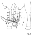
- Figure 1 shows a cow 1 of which only the hind legs are shown with an udder 2, with four teats 3, in which a device 4 according to the invention is arranged around the teats 3 of the udder 4 of the cow 1.
- the device 4 for pneumatically milking a cow here comprises four milk extractors, which each comprise a teat cup 5 and a milk line 6, the milk lines 6 supplying the milk to a milk collection chamber 7, from where the milk is transported to a central storage via common discharge line 25.
- Each teat cup 5 is connected via line 8 to a source of changing underpressure, with the help of which the milking is carried out.
- the milk line 6 is provided with a supply line 9, which supply lines 9 are connected to manifold 10 for cleansing liquid, such as iodine, which is supplied via line 11.
- manifold 10 for cleansing liquid such as iodine
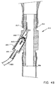
- a coupling piece 14 is clamped in the lower end of the teat cup 5, which coupling piece forms the upper end of the milk line 6, of which the remaining hose-shaped part is clamped on the lower end of the coupling piece 14.
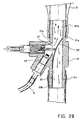
- the coupling piece 14 defines a vertical passage 24 which has a rectangular cross-section and on two opposite inner surfaces is provided with a curved step 22, which forms a valve seat.
- a leaf spring 21 is placed, which at the location of the portion 21b is fixed arranged to said inner surface, in a manner comparable to a restraint, but for the rest can be bent freely in the direction to the right, until in abutment with the seat 22. Also see the discussion of the leaf spring 121 of the figures 3A, 3B.
- the coupling piece 14 is formed with two blocks 30 and 31, in which on the block 30 a supply line 9 for cleansing liquid such as iodine is connected, which supply line may lead to a manifold for cleansing liquid such as the manifold 10 mentioned before in figure 1.
- a supply line 9 for cleansing liquid such as iodine
- a manifold for cleansing liquid such as the manifold 10 mentioned before in figure 1.
- an own line for dosing cleansing liquid can be connected.
- a bore hole 40 is formed, which ends in a debouching 17, which is covered by the leaf spring 21.
- a one way valve 19 is placed with valve 19a.
- the valve 19a will move from the seat to the debouching 17 and as a result make a passage of pressurized air with cleansing liquid past it possible.
- a bore hole 41 is arranged, which is provided with a screw thread 38.
- a bush 32 provided with an external screw thread 37 is screwed, which is closed off towards the debouching 17 by a plate 42 with a hole 43 and on the other side is provided with a connection nipple 33 for a pressurized air lead 34.
- a piston pin 35 Within the bush 32 is a piston pin 35, around which a compression spring 36 has been placed, which on the one side abuts against the plate 42 and on the other side abuts against a piston forming a unity with the piston pin 35 which piston is not further shown.
- the control means first pressurize the line 34 so that the piston or pusher pin 35 presses the leaf spring 21 to the inside in the passage 24, until the leaf spring 21 with the longitudinal edges abuts the seat 22 and with the upper edge 21 a abuts the opposite surface 24a of the passage 24.
- the length of the leaf spring here is adjusted to the dimensions of the passage 24 and the course of the seat 22.
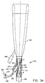
- FIG 3A shows the upper end of a milk extractor, in which a teat cup 105 is connected to the rest of the milk line 106 via a coupling piece 113 which is a part of the milk line and in which an important part of this embodiment of the invention is accommodated.
- the coupling piece 113 has a milk passage 124 and a branch 115 for the supply line 109.
- the branch 115 debouches at the level of the outlet 117 in the milk passage 124.
- the opening 117 is shown in a situation in figure 3A in which milking takes place and milks flows in the direction A, covered by a strip-shaped valve 121, comparable to leaf spring 21 and therefore consisting of a metal leaf spring, which for instance is 4 cm long and for 1 cm fixed to the inner wall of the passage 124, so that as it were a restraint is formed.
- the remaining 3 cm of the leaf spring can be bent towards the passage 124 under the influence of an (air)pressure load, until the leaf spring 121 sealingly abuts the step 122 formed in the wall of the passage 124, which step forms the valve seat.
- the curve of the seat is similar again to the curve of the leaf spring 121 as a result of the evenly distributed load.
- the passage 124 has a square cross-section in order to facilitate the movement of the leaf spring 124.
- the supply of the cleansing liquid here takes place in an alternative manner.
- a line 118 debouches, in which also a valve 119 is accommodated and through which line cleansing liquid dosed in a for the teat concerned wanted quantity (preferably 5-7 cc) is introduced into the line 109.
- a line 120 connected to the central pressure source - controlled by the central control means that are not shown- air is supplied at the wanted moment under the wanted pressure, as a result of which the liquid is transported along and the leaf spring 121 is pressed open and bent until in abutment with the seat 122, as is shown in figure 3B.
- the cleansing liquid is guided along by the leaf spring 121 also and moves upwards in the direction B towards the teat (not shown). A returning movement of the cleansing liquid downwards, in the direction C to the rest of the milk line is prevented by the leaf spring 121 abutting the seat 122. Cleansing liquid can in that case possibly get back into the branch 115, which is not a problem.
- the increased pressure is maintained for some seconds, for instance 5 seconds, after the cleansing liquid has been emitted.
- the cups can be urged from the teats, but also any risk of the cleansing medium flowing back into the milk line is prevented, because as a result of the pressure the leaf spring 21, 121 keeps on closing off the milk line 6, 106, until the teat cups have fallen off the teats and no returning pressure blast may occur.
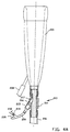
- FIG 4A shows a teat cup 205 to which a coupling piece 213 had been connected.
- Line 208 is the line to the source of changing underpressure.
- the coupling piece 213 consists of a tube-shaped part 214 with two ends to which the milk line 206 is connected to both the upper side and the lower side, just below the teat cup 205 and has a branch 215 for a supply line 209 for a cleansing medium.
- a valve 216 is accommodated on the one hand to be able to discharge the cleansing liquid at the wanted moment and for the wanted time and on the other hand preventing the milk from entering the supply line 209 of the cleansing liquid.
- a tube 217 has been arranged, which extends into the milk line 206 and with the help of a mandrel (not shown here) is pressed into the wanted shape. As a result the round tube is bent and pressed flat against the wall of the milk line.
- the jet of the cleansing liquid which is supplied through the supply line 209 will be squirted out of tube 217 and directed parallel to the centre line of the teat cup 205 at the teat (not shown).
- a line 218 debouches, in which also a valve 219 is accommodated and through which line, dosed in the wanted quantity, the cleansing liquid is introduced into the line 209.
- air is supplied at the wanted moment under the wanted pressure, as a result of which the quantity of liquid introduced in the line will be squirted in the teat cup 205 via the valve 216.
- FIG 4B shows a coupling piece 214 from figure 4A strongly enlarged.
- a valve 216 is arranged in its branch, to which a connection end 221 for the supply hose 209 for the air and cleansing liquid is arranged.
- the valve 216 is designed here as a valve 222, which with the help of a spring 223 is pressed on the seat 224.
- the valve 222 is pressed to the outside counter to the activity of the compression spring 223 by the pressure of the air with the cleansing liquid, after which the cleansing liquid is squirted upwards in the teat cup on the teat via the flattened tube 217.
- figure 5 the method is shown in four stages, figure 5A showing the teat 203 with the teat cup 205, while the cleansing liquid together with the air flow 225 is blown into the inside of the teat cup 205 via the outlet of the flattened tube 217, directed at the teat end 226.
- the air flow 225 is directed at the milk residues 227 which are at the lower end of the cow's teat.
- figure 5B the moment is shown that the inner lining 228 of the teat cup 205 is pressed to the outside by the incoming air flow and the milk residue with the cleansing liquid 229 blown in is blown upwards and subsequently as shown in figure 5C to the upper side of the teat cup and possibly after that to the outside as shown in figure 5D.
- the release of the teat cup 205 from the teat 302 as a result is particularly promoted and the teat cup 205 will afterwards be able to fall down.
- the cow's teat as well as the inside of the teat cup will then be entirely cleansed from milk residues and also disinfected with the help of the disinfecting liquid.
Landscapes
- Life Sciences & Earth Sciences (AREA)
- Animal Husbandry (AREA)
- Environmental Sciences (AREA)
- Cleaning In General (AREA)
- Dairy Products (AREA)
- External Artificial Organs (AREA)
- Apparatus For Making Beverages (AREA)
Claims (38)
- Dispositif (4) pour traire de manière pneumatique une vache, comprenant un certain nombre d'extracteurs de lait, comprenant chacun un gobelet trayeur (5 ; 105), ainsi qu'un lactoduc (6 ; 106) relié à l'extrémité inférieure du gobelet trayeur, qui mène du gobelet trayeur à une chambre (7) de collecte du lait provenant des gobelets trayeurs, dans lequel le dispositif est muni, pour chaque extracteur de lait, d'une alimentation (9 ; 109) en agent de nettoyage, tel qu'un désinfectant, dirigée sur le gobelet trayeur, en particulier sur le trayon se trouvant dans le gobelet trayeur, chaque alimentation comprenant une conduite (9 ; 109) qui, à l'emplacement d'une sortie, débouche dans l'extracteur de lait concerné, en particulier dans le lactoduc, caractérisé en ce que chaque extracteur de lait est muni d'un moyen (21 ; 121) permettant de fermer l'extracteur de lait à proximité ou en aval de la sortie, de préférence au niveau de celle-ci, lors de la décharge de l'agent de nettoyage par la sortie.
- Dispositif selon la revendication 1, le moyen de fermeture (21 ; 121) étant placé près de la jonction entre le gobelet trayeur (5 ; 105) et le lactoduc.
- Dispositif selon la revendication 1 ou 2, le moyen de fermeture (21 ; 121) fermant la conduite d'alimentation (9 ; 109) lorsqu'il est en position désactivée.
- Dispositif selon la revendication 3, le moyen de fermeture (21 ; 121) fermant la sortie de la conduite d'alimentation (9 ; 109) lorsqu'il est en position désactivée.
- Dispositif selon la revendication 4, le moyen de fermeture comprenant un élément de fermeture (21 ; 121) qui peut effectuer un mouvement de va-et-vient entre une position de traite, dans laquelle il ferme la sortie, et une position de nettoyage, dans laquelle il ferme l'extracteur de lait.
- Dispositif selon la revendication 5, l'élément de fermeture (21 ; 121) ayant des plans permettant de diriger l'agent de nettoyage dans l'extracteur de lait dans la direction du gobelet trayeur (5 ; 105), la conduite d'alimentation (9 ; 109) débouchant de préférence avec une composante en direction du trayon.
- Dispositif selon la revendication 5 ou 6, comprenant en outre un moyen pour incliner l'élément de fermeture (21 ; 121) se trouvant en position de nettoyage vers la position de traite.
- Dispositif selon la revendication 7, l'élément de fermeture comprenant une bande de matière flexible élastiquement (21 ; 121) fixée à une extrémité (21b), qui peut être déplacée par flexion de la position de traite vers la position de nettoyage.
- Dispositif selon la revendication 8, la bande flexible élastiquement (21 ; 121) étant fixée dans l'extracteur de lait, en aval de la sortie.
- Dispositif selon la revendication 8 ou 9, un siège (22 ; 122) étant placé dans l'extracteur de lait pour supporter de manière étanche l'élément de fermeture (21 ; 121) en position de nettoyage.
- Dispositif selon la revendication 10, le siège (22 ; 122) ayant une course incurvée suivant la ligne de courbure de l'élément de fermeture.
- Dispositif selon la revendication 10 ou 11, le siège (22 ; 122) étant formé dans la paroi de l'extracteur de lait, en particulier dans le lactoduc.
- Dispositif selon l'une quelconque des revendications 8 à 12, la bande (21 ; 121) étant constituée de métal et étant, en particulier, une lame ressort.
- Dispositif selon l'une quelconque des revendications précédentes, pourvu en outre d'un moyen de manoeuvre (34, 35 ; 120) pour le moyen de fermeture (21 ; 121), ainsi que d'un moyen de commande permettant de commander le moyen de manoeuvre en fonction de la décharge de l'agent de nettoyage.
- Dispositif selon la revendication 14, le moyen de manoeuvre comprenant un organe de manoeuvre (35), qui peut être déplacé entre une position active, qui place le moyen de fermeture (21) en position de fermeture, et une position de repos.
- Dispositif selon la revendication 15, l'organe de manoeuvre (35), en position active, étant adapté pour pousser le moyen de fermeture (21) vers la position de fermeture, de préférence à l'encontre d'une force de rappel.
- Dispositif selon la revendication 16, l'organe de manoeuvre (35) étant mis en contact par pression avec le moyen de fermeture (21).
- Dispositif selon la revendication 17, l'organe de manoeuvre comprenant un élément formant poussoir (35) et le moyen de fermeture comprenant un élément de fermeture (21) qui, au moins en position de repos, est incliné vers l'organe de manoeuvre.
- Dispositif selon l'une quelconque des revendications 15 à 18, l'organe de manoeuvre (35) et la sortie de la conduite d'alimentation étant situés sur le même côté de l'extracteur de lait.
- Dispositif selon l'une quelconque des revendications 14 à 19, le moyen de commande étant adapté pour activer un moyen destiné à mettre sous pression la conduite d'alimentation au moment de, ou peu après, l'activation du moyen de manoeuvre (34, 35 ; 120) du moyen de fermeture (21 ; 121).
- Dispositif selon la revendication 20, le moyen de commande étant adapté pour activer le moyen destiné à mettre sous pression la conduite d'alimentation (9) peu après l'activation du moyen de manoeuvre (34, 35) du moyen de fermeture.
- Dispositif selon la revendication 21, le moyen de manoeuvre comprenant une conduite de manoeuvre (34), par exemple pneumatique, qui est séparée de la conduite d'alimentation (9).
- Dispositif selon la revendication 14, le moyen de fermeture (121) étant adapté pour être activé sous l'effet d'une montée en pression dans la conduite d'alimentation (109).
- Dispositif selon la revendication 14 ou 15, le moyen de manoeuvre comprenant une conduite de manoeuvre, par exemple pneumatique, qui coïncide avec la conduite d'alimentation.
- Dispositif selon l'une quelconque des revendications précédentes, le moyen de fermeture étant logé dans un élément de couplage (14 ; 113) qui est placé dans l'extracteur de lait, de préférence à proximité de la jonction entre le gobelet trayeur (5 ; 105) et le lactoduc (6 ; 106).
- Elément de couplage (14 ; 113) adapté pour un dispositif selon la revendication 25.
- Procédé pour nettoyer et/ou désinfecter les trayons d'une mamelle de vache, lorsque la vache a été traite à l'aide d'un dispositif pneumatique de traite d'une vache, lequel dispositif comprend une chambre de collecte de lait et un système comportant des extracteurs de lait, qui comprennent chacun un gobelet trayeur et un lactoduc s'étendant entre le gobelet trayeur concerné et la chambre de collecte de lait, juste après la fin de la traite, mais avant que le gobelet trayeur soit retiré du trayon, dans lequel une certaine quantité de liquide de nettoyage est introduite dans le gobelet trayeur par l'intermédiaire d'une conduite d'alimentation et d'une sortie de cette dernière dans l'extracteur de lait, caractérisé en ce que simultanément ou peu après l'extracteur de lait, en particulier le lactoduc, est fermé à proximité ou en aval de la sortie de la conduite d'alimentation.
- Procédé selon la revendication 27, le liquide de nettoyage incluant un gaz porteur sous pression, tel que de l'air, étant fourni pendant une certaine période de temps, dont la durée est telle que l'écoulement du gaz souffle tout d'abord le liquide de nettoyage dans le gobelet trayeur, puis souffle le contenu du gobelet trayeur vers l'extérieur, de sorte que le gobelet trayeur soit libéré du trayon, l'extracteur de lait restant fermé en aval de la sortie au moins jusqu'à ce que le gobelet trayeur soit libéré.
- Procédé selon la revendication 27 ou 28, la fin de la certaine période de temps, durant laquelle l'écoulement du gaz se poursuit, correspondant plus ou moins au moment où le gobelet trayeur est pivoté d'un demi tour après avoir été complètement libéré du trayon.
- Procédé selon la revendication 29, la période de temps, durant laquelle l'écoulement du gaz se poursuit, étant environ de 5 secondes.
- Procédé selon l'une quelconque des revendications 27 à 30, la certaine quantité de liquide de nettoyage ou de désinfectant étant comprise entre 5 et 7 cm3.
- Procédé selon l'une quelconque des revendications 27 à 31, la fermeture de l'extracteur de lait étant effectuée à l'aide d'un élément de fermeture qui est poussé dans une position de nettoyage qui ferme l'extracteur de lait avant ou pendant la décharge de l'agent de nettoyage.
- Procédé selon la revendication 32, la fermeture au moyen de l'élément de fermeture étant due à un contact mécanique entre l'élément de fermeture et le moyen de manoeuvre, de préférence une butée ou un contact par pression.
- Procédé selon la revendication 33, le moyen de manoeuvre étant incliné vers la position de repos.
- Procédé selon la revendication 32, la fermeture au moyen de l'élément de fermeture se produisant sous l'effet de la pression de l'écoulement du gaz.
- Procédé selon l'une quelconque des revendications 32 à 35, la sortie étant fermée lorsque l'élément de fermeture se trouve en position de repos.
- Procédé selon l'une quelconque des revendications 32 à 36, l'écoulement du gaz et le liquide de nettoyage étant guidés par l'élément de fermeture en direction du trayon.
- Système comportant un certain nombre de dispositifs selon l'une quelconque des revendications 1 à 25 précédentes et un stockage central du lait relié à leur chambre de collecte de lait.
Applications Claiming Priority (7)
| Application Number | Priority Date | Filing Date | Title |
|---|---|---|---|
| NL1009461A NL1009461C2 (nl) | 1998-06-22 | 1998-06-22 | Werkwijze en inrichting voor het reinigen van de tepels van de uier na het melken van een koe. |
| NL1009461 | 1998-06-22 | ||
| NL1011104 | 1999-01-21 | ||
| NL1011104 | 1999-01-21 | ||
| NL1011765A NL1011765C2 (nl) | 1999-01-21 | 1999-04-09 | Melkinrichting voorzien van reinigingsmiddelen. |
| NL1011765 | 1999-04-09 | ||
| PCT/NL1999/000384 WO1999066787A1 (fr) | 1998-06-22 | 1999-06-22 | Machine a traire dotee d'un organe de nettoyage |
Publications (2)
| Publication Number | Publication Date |
|---|---|
| EP1089615A1 EP1089615A1 (fr) | 2001-04-11 |
| EP1089615B1 true EP1089615B1 (fr) | 2003-03-26 |
Family
ID=27351190
Family Applications (1)
| Application Number | Title | Priority Date | Filing Date |
|---|---|---|---|
| EP99929948A Expired - Lifetime EP1089615B1 (fr) | 1998-06-22 | 1999-06-22 | Machine a traire dotee d'un organe de nettoyage |
Country Status (10)
| Country | Link |
|---|---|
| US (1) | US6644240B1 (fr) |
| EP (1) | EP1089615B1 (fr) |
| JP (1) | JP2002518029A (fr) |
| CN (1) | CN1306389A (fr) |
| AU (1) | AU4658099A (fr) |
| BR (1) | BR9911419A (fr) |
| CA (1) | CA2335574A1 (fr) |
| DE (1) | DE69906288T2 (fr) |
| ES (1) | ES2195580T3 (fr) |
| WO (1) | WO1999066787A1 (fr) |
Cited By (14)
| Publication number | Priority date | Publication date | Assignee | Title |
|---|---|---|---|---|
| US8025029B2 (en) | 2004-06-12 | 2011-09-27 | Gea Farm Technologies, Inc. | Automatic dairy animal milker unit backflusher and teat dip applicator system and method |
| US8033247B2 (en) | 2004-06-12 | 2011-10-11 | Gea Farm Technologies, Inc. | Automatic dairy animal milker unit backflusher and teat dip applicator system and method |
| US8336502B2 (en) | 2008-11-10 | 2012-12-25 | Gea Farm Technologies Gmbh | Method and device for automatically bringing a fluid into contact with the teats of an animal |
| US8342125B2 (en) | 2004-06-12 | 2013-01-01 | Gea Farm Technologies, Inc. | Safety valve for an automatic dairy animal milker unit backflusher and teat dip applicator |
| US8770146B2 (en) | 2009-09-04 | 2014-07-08 | Gea Farm Technologies, Inc. | Methods and apparatus for applying teat dip to a dairy animal |
| US8925483B2 (en) | 2010-02-22 | 2015-01-06 | Gea Farm Technologies, Inc. | Dairy harvesting facility with milk line protection system and methods |
| US8991335B2 (en) | 2008-06-27 | 2015-03-31 | Gea Farm Technologies, Inc. | Milk tube dome with flow controller |
| US9526224B2 (en) | 2013-12-20 | 2016-12-27 | Gea Farm Technologies Gmbh | Safety valve device |
| US10502330B2 (en) | 2013-12-20 | 2019-12-10 | Gea Farm Technologies Gmbh | Safety valve |
| US10681895B2 (en) | 2010-02-22 | 2020-06-16 | Gea Farm Technologies, Inc. | Dairy animal milking preparation system and methods |
| US10874084B2 (en) | 2004-06-12 | 2020-12-29 | Gea Farm Technologies, Inc. | Safety valve for a dairy system component |
| US11015722B2 (en) | 2016-05-04 | 2021-05-25 | Gea Farm Technologies Gmbh | Safety valve |
| US11206805B2 (en) | 2017-11-03 | 2021-12-28 | Gea Farm Technologies Gmbh | Automated milking system safety valve arrangement |
| US11723341B2 (en) | 2009-09-04 | 2023-08-15 | Gea Farm Technologies, Inc. | Safety valve for an automated milker unit backflushing and teat dip applicator system |
Families Citing this family (32)
| Publication number | Priority date | Publication date | Assignee | Title |
|---|---|---|---|---|
| US6752102B2 (en) * | 1999-09-27 | 2004-06-22 | Pro Chemicals, Llc | Apparatus for producing a foam bovine teat dip |
| US7290497B2 (en) | 2001-09-21 | 2007-11-06 | Westfaliasurge, Inc. | Milking device provided with cleansing means |
| US20080022932A1 (en) * | 2001-09-21 | 2008-01-31 | Westfaliasurge, Inc. | Milking device provided with cleansing means |
| NL1016237C2 (nl) * | 2000-09-22 | 2002-03-25 | Rieberjo B V | Melkinrichting voorzien van reinigingsmiddelen. |
| DE10100840C2 (de) * | 2001-01-10 | 2003-01-30 | Westfalia Landtechnik Gmbh | Verfahren und Vorrichtung zum Melken |
| US6895892B2 (en) | 2002-10-01 | 2005-05-24 | Westfaliasurge, Inc. | Short milk tube |
| SE0301934L (sv) * | 2003-06-30 | 2005-02-22 | Delaval Holding Ab | Mjölkningsanordning och förfarande för hantering av en mjölkningsanordning |
| DK1679956T4 (en) † | 2003-10-22 | 2018-04-03 | An Udder Ip Company Ltd | Milking equipment and method. |
| GB0408968D0 (en) | 2004-04-22 | 2004-05-26 | Duke James R J | Milking equipment |
| WO2005072516A1 (fr) * | 2004-01-30 | 2005-08-11 | James Richard John Duke | Materiel de traite |
| GB0518976D0 (en) † | 2005-09-16 | 2005-10-26 | Duke James R J | Teat cup |
| US20070074673A1 (en) * | 2005-09-30 | 2007-04-05 | Pro-Chemicals Llc | System and method for foaming liquid |
| NL1031749C2 (nl) | 2006-05-04 | 2007-11-06 | Jacob Hendrik Berthold Dietric | Melkklauwinrichting. |
| NL1031764C2 (nl) | 2006-05-08 | 2007-11-13 | Jacob Hendrik Berthold Dietric | Melkklauwinrichting eventueel met reinigingsfunctie. |
| WO2008030084A2 (fr) * | 2006-09-05 | 2008-03-13 | Maasland N.V. | Outil de traite |
| NZ585871A (en) * | 2007-12-19 | 2011-12-22 | Gea Farm Technologies Gmbh | Milk collecting pieces with closable chambers |
| EP2473026B1 (fr) * | 2009-09-04 | 2014-07-02 | GEA Farm Technologies, Inc. | Appareil de rinçage à contre-courant automatique pour unité de traite automatique d'animal laitier et système et procédé relatifs à un applicateur de produit de trempage des trayons |
| RU2654747C2 (ru) * | 2013-05-02 | 2018-05-22 | Делаваль Холдинг Аб | Картридж и доильный стакан |
| NL2010864C2 (en) * | 2013-05-27 | 2014-12-01 | M Van Wenum Holding B V | Disinfection dip system for a nipple. |
| US9072274B2 (en) * | 2013-08-29 | 2015-07-07 | Terry S. Ewert | Devices and methods for preparing animals for milking |
| CN104027184B (zh) * | 2014-04-16 | 2016-03-23 | 黑龙江省兽医科学研究所 | 一种奶牛乳头药浴车 |
| CA2966997C (fr) | 2014-11-07 | 2022-06-28 | Gea Farm Technologies, Inc. | Tube de lait court avec eventprotecteur pour unite de traite d'animal laitier |
| CN104982338B (zh) * | 2015-07-13 | 2017-05-03 | 江苏银蕨智能科技有限公司 | 一种智能挤奶系统及方法 |
| CN105123533B (zh) * | 2015-09-07 | 2017-07-04 | 北京京鹏环宇畜牧科技股份有限公司 | 一种挤奶杯组变频清洗装置及清洗方法 |
| USD830649S1 (en) | 2016-01-28 | 2018-10-09 | Gea Farm Technologies, Inc. | Vent protecting stiffener for a dairy animal milker unit tube |
| CN105941165B (zh) * | 2016-06-22 | 2019-10-01 | 中国农业科学院农业信息研究所 | 一种智能挤奶系统 |
| CN107080603B (zh) * | 2017-05-10 | 2019-01-08 | 重庆市长寿区莲莲奶牛养殖场 | 奶牛乳头消毒车 |
| GB201902189D0 (en) * | 2019-02-18 | 2019-04-03 | Avon Polymer Prod Ltd | Milking apparatus |
| US11632931B2 (en) | 2019-08-19 | 2023-04-25 | Gea Farm Technologies, Inc. | Milker unit short milk tube with milk claw end connector |
| US11516990B2 (en) | 2019-08-19 | 2022-12-06 | Gea Farm Technologies, Inc. | Milker unit short milk tube with milk claw end connector |
| CN111328716A (zh) * | 2020-04-02 | 2020-06-26 | 安徽科技学院 | 转盘式挤奶机器人 |
| USD1022350S1 (en) | 2021-09-22 | 2024-04-09 | Gea Farm Technologies, Inc. | Milker unit short milk tube milk claw end connector |
Family Cites Families (9)
| Publication number | Priority date | Publication date | Assignee | Title |
|---|---|---|---|---|
| DE2622794A1 (de) | 1976-05-21 | 1977-12-08 | Alfa Laval Agrar Gmbh | Verfahren und vorrichtung zur automatisierten anwendung von sanitisern an strichen und melkzeug |
| EP0332235B2 (fr) | 1985-07-01 | 1998-12-30 | C. van der Lely N.V. | Dispositif de traite automatique d'animaux |
| EP0543463B1 (fr) | 1991-11-22 | 2001-03-21 | Berthold Johannes Theodor Dietrich | Dispositif de traite et gobelet trayeur pour ce dispositif |
| US5850845A (en) * | 1996-10-17 | 1998-12-22 | Pereira Construction, Inc. | Backflush valve for milking machine system |
| NL1004921C2 (nl) * | 1996-12-31 | 1998-07-01 | Prolion Bv | Inrichting en werkwijze voor het melken van dieren. |
| US6089242A (en) * | 1998-02-10 | 2000-07-18 | Babson Bros. Co. | Dairy harvesting facility wash system |
| SE9704781D0 (sv) * | 1997-12-19 | 1997-12-19 | Alfa Laval Agri Ab | A method and an apparatus for separation of foremilk |
| NL1009663C2 (nl) * | 1998-07-06 | 2000-01-10 | Maasland Nv | Werkwijze en inrichting voor het desinfecteren van een melkinstallatie en/of een reinigingsinrichting voor de spenen van een dier. |
| US6302058B1 (en) * | 1999-09-27 | 2001-10-16 | North West Environmental Systems, Inc. | Apparatus and method for producing a foam bovine teat dip |
-
1999
- 1999-06-22 AU AU46580/99A patent/AU4658099A/en not_active Abandoned
- 1999-06-22 JP JP2000555487A patent/JP2002518029A/ja active Pending
- 1999-06-22 WO PCT/NL1999/000384 patent/WO1999066787A1/fr active IP Right Grant
- 1999-06-22 BR BR9911419-4A patent/BR9911419A/pt not_active Application Discontinuation
- 1999-06-22 EP EP99929948A patent/EP1089615B1/fr not_active Expired - Lifetime
- 1999-06-22 DE DE69906288T patent/DE69906288T2/de not_active Expired - Lifetime
- 1999-06-22 CA CA002335574A patent/CA2335574A1/fr not_active Abandoned
- 1999-06-22 CN CN99807663A patent/CN1306389A/zh active Pending
- 1999-06-22 ES ES99929948T patent/ES2195580T3/es not_active Expired - Lifetime
- 1999-06-22 US US09/719,619 patent/US6644240B1/en not_active Expired - Lifetime
Cited By (27)
| Publication number | Priority date | Publication date | Assignee | Title |
|---|---|---|---|---|
| US11540484B2 (en) | 2004-06-12 | 2023-01-03 | Gea Farm Technologies, Inc. | Safety valve for a dairy system component |
| US9468189B2 (en) | 2004-06-12 | 2016-10-18 | Gea Farm Technologies, Inc. | Safety valve for an automated milker unit backflushing and teat dip applicator system |
| US9510556B2 (en) | 2004-06-12 | 2016-12-06 | Gea Farm Technologies, Inc. | Dosage valve for a backflushing and teat dip applicator system |
| US8342125B2 (en) | 2004-06-12 | 2013-01-01 | Gea Farm Technologies, Inc. | Safety valve for an automatic dairy animal milker unit backflusher and teat dip applicator |
| US8528500B2 (en) | 2004-06-12 | 2013-09-10 | Gea Farm Technologies, Inc. | Automatic dairy animal milker unit backflusher and teat dip applicator system and method |
| US8590486B2 (en) | 2004-06-12 | 2013-11-26 | Gea Farm Technologies, Inc. | Safety valve for an automatic dairy animal milker unit backflusher and teat dip applicator |
| US8033247B2 (en) | 2004-06-12 | 2011-10-11 | Gea Farm Technologies, Inc. | Automatic dairy animal milker unit backflusher and teat dip applicator system and method |
| US8025029B2 (en) | 2004-06-12 | 2011-09-27 | Gea Farm Technologies, Inc. | Automatic dairy animal milker unit backflusher and teat dip applicator system and method |
| US9491925B2 (en) | 2004-06-12 | 2016-11-15 | Gea Farm Technologies, Inc. | Valve block for a backflushing and teat dip applicator system |
| US9072273B2 (en) | 2004-06-12 | 2015-07-07 | Gea Farm Technologies, Inc. | Automatic dairy animal milker unit backflusher and teat dip applicator system and method |
| US10874084B2 (en) | 2004-06-12 | 2020-12-29 | Gea Farm Technologies, Inc. | Safety valve for a dairy system component |
| US9545079B2 (en) | 2008-06-27 | 2017-01-17 | Gea Farm Technologies, Inc. | Milk tube dome with flow controller |
| US8991335B2 (en) | 2008-06-27 | 2015-03-31 | Gea Farm Technologies, Inc. | Milk tube dome with flow controller |
| US10499610B2 (en) | 2008-06-27 | 2019-12-10 | Gea Farm Technologies, Inc. | Milk tube dome with flow controller |
| US8336502B2 (en) | 2008-11-10 | 2012-12-25 | Gea Farm Technologies Gmbh | Method and device for automatically bringing a fluid into contact with the teats of an animal |
| US9504226B2 (en) | 2009-09-04 | 2016-11-29 | Gea Farm Technologies, Inc. | Methods and apparatus for applying teat dip to a dairy animal |
| US8770146B2 (en) | 2009-09-04 | 2014-07-08 | Gea Farm Technologies, Inc. | Methods and apparatus for applying teat dip to a dairy animal |
| US11723341B2 (en) | 2009-09-04 | 2023-08-15 | Gea Farm Technologies, Inc. | Safety valve for an automated milker unit backflushing and teat dip applicator system |
| US10681895B2 (en) | 2010-02-22 | 2020-06-16 | Gea Farm Technologies, Inc. | Dairy animal milking preparation system and methods |
| US8925483B2 (en) | 2010-02-22 | 2015-01-06 | Gea Farm Technologies, Inc. | Dairy harvesting facility with milk line protection system and methods |
| US11627718B2 (en) | 2010-02-22 | 2023-04-18 | Gea Farm Technologies, Inc. | Dairy animal milking preparation system and methods |
| US9526224B2 (en) | 2013-12-20 | 2016-12-27 | Gea Farm Technologies Gmbh | Safety valve device |
| US10502330B2 (en) | 2013-12-20 | 2019-12-10 | Gea Farm Technologies Gmbh | Safety valve |
| US11015722B2 (en) | 2016-05-04 | 2021-05-25 | Gea Farm Technologies Gmbh | Safety valve |
| US11206805B2 (en) | 2017-11-03 | 2021-12-28 | Gea Farm Technologies Gmbh | Automated milking system safety valve arrangement |
| US11617343B2 (en) | 2017-11-03 | 2023-04-04 | Gea Farm Technologies Gmbh | Automated teat dip fluid manifold |
| US11930782B2 (en) | 2017-11-03 | 2024-03-19 | Gea Farm Technologies Gmbh | Automated milking system safety valve arrangement |
Also Published As
| Publication number | Publication date |
|---|---|
| WO1999066787A1 (fr) | 1999-12-29 |
| JP2002518029A (ja) | 2002-06-25 |
| DE69906288D1 (de) | 2003-04-30 |
| US6644240B1 (en) | 2003-11-11 |
| EP1089615A1 (fr) | 2001-04-11 |
| CA2335574A1 (fr) | 1999-12-29 |
| DE69906288T2 (de) | 2003-12-04 |
| AU4658099A (en) | 2000-01-10 |
| CN1306389A (zh) | 2001-08-01 |
| BR9911419A (pt) | 2001-03-20 |
| ES2195580T3 (es) | 2003-12-01 |
Similar Documents
| Publication | Publication Date | Title |
|---|---|---|
| EP1089615B1 (fr) | Machine a traire dotee d'un organe de nettoyage | |
| NL1016237C2 (nl) | Melkinrichting voorzien van reinigingsmiddelen. | |
| EP1219167B1 (fr) | Machine pour la traite d'animaux, tels que des vaches | |
| EP0543463B1 (fr) | Dispositif de traite et gobelet trayeur pour ce dispositif | |
| US7290497B2 (en) | Milking device provided with cleansing means | |
| EP1046336B1 (fr) | Dispositif pour la traite d'animaux | |
| EP1933616B1 (fr) | Gobelet de trayeuse | |
| US20040089242A1 (en) | Device intended for injecting a fluid into a system comprising a milk cup and a milk line | |
| EP0805622B2 (fr) | Dispositif pour traire les animaux | |
| US20030101939A1 (en) | Cleaning device | |
| CA2529582A1 (fr) | Dispositif de traite et procede de manipulation d'un dispositif de traite | |
| NL1011765C2 (nl) | Melkinrichting voorzien van reinigingsmiddelen. | |
| MXPA00013011A (es) | Dispositivo de ordeña provisto de medios limpiadores | |
| EP0626129B2 (fr) | Dispositif de traite d'animaux | |
| NL1009461C2 (nl) | Werkwijze en inrichting voor het reinigen van de tepels van de uier na het melken van een koe. | |
| EP1321029A3 (fr) | Dispositif et gobelet trayeur pour la traite d'animaux | |
| WO2005110069A1 (fr) | Machine a traire et element raccord |
Legal Events
| Date | Code | Title | Description |
|---|---|---|---|
| PUAI | Public reference made under article 153(3) epc to a published international application that has entered the european phase |
Free format text: ORIGINAL CODE: 0009012 |
|
| 17P | Request for examination filed |
Effective date: 20010119 |
|
| AK | Designated contracting states |
Kind code of ref document: A1 Designated state(s): BE CH DE DK ES FR GB IT LI NL SE |
|
| 17Q | First examination report despatched |
Effective date: 20010711 |
|
| GRAG | Despatch of communication of intention to grant |
Free format text: ORIGINAL CODE: EPIDOS AGRA |
|
| GRAG | Despatch of communication of intention to grant |
Free format text: ORIGINAL CODE: EPIDOS AGRA |
|
| GRAH | Despatch of communication of intention to grant a patent |
Free format text: ORIGINAL CODE: EPIDOS IGRA |
|
| GRAH | Despatch of communication of intention to grant a patent |
Free format text: ORIGINAL CODE: EPIDOS IGRA |
|
| GRAA | (expected) grant |
Free format text: ORIGINAL CODE: 0009210 |
|
| AK | Designated contracting states |
Designated state(s): BE CH DE DK ES FR GB IT LI NL SE |
|
| PG25 | Lapsed in a contracting state [announced via postgrant information from national office to epo] |
Ref country code: LI Free format text: LAPSE BECAUSE OF FAILURE TO SUBMIT A TRANSLATION OF THE DESCRIPTION OR TO PAY THE FEE WITHIN THE PRESCRIBED TIME-LIMIT Effective date: 20030326 Ref country code: IT Free format text: LAPSE BECAUSE OF FAILURE TO SUBMIT A TRANSLATION OF THE DESCRIPTION OR TO PAY THE FEE WITHIN THE PRESCRIBED TIME-LIMIT;WARNING: LAPSES OF ITALIAN PATENTS WITH EFFECTIVE DATE BEFORE 2007 MAY HAVE OCCURRED AT ANY TIME BEFORE 2007. THE CORRECT EFFECTIVE DATE MAY BE DIFFERENT FROM THE ONE RECORDED. Effective date: 20030326 Ref country code: FR Free format text: LAPSE BECAUSE OF FAILURE TO SUBMIT A TRANSLATION OF THE DESCRIPTION OR TO PAY THE FEE WITHIN THE PRESCRIBED TIME-LIMIT Effective date: 20030326 Ref country code: CH Free format text: LAPSE BECAUSE OF FAILURE TO SUBMIT A TRANSLATION OF THE DESCRIPTION OR TO PAY THE FEE WITHIN THE PRESCRIBED TIME-LIMIT Effective date: 20030326 Ref country code: BE Free format text: LAPSE BECAUSE OF FAILURE TO SUBMIT A TRANSLATION OF THE DESCRIPTION OR TO PAY THE FEE WITHIN THE PRESCRIBED TIME-LIMIT Effective date: 20030326 |
|
| REG | Reference to a national code |
Ref country code: GB Ref legal event code: FG4D |
|
| REG | Reference to a national code |
Ref country code: CH Ref legal event code: EP |
|
| REF | Corresponds to: |
Ref document number: 69906288 Country of ref document: DE Date of ref document: 20030430 Kind code of ref document: P |
|
| PG25 | Lapsed in a contracting state [announced via postgrant information from national office to epo] |
Ref country code: DK Free format text: LAPSE BECAUSE OF FAILURE TO SUBMIT A TRANSLATION OF THE DESCRIPTION OR TO PAY THE FEE WITHIN THE PRESCRIBED TIME-LIMIT Effective date: 20030626 |
|
| REG | Reference to a national code |
Ref country code: SE Ref legal event code: TRGR |
|
| REG | Reference to a national code |
Ref country code: CH Ref legal event code: PL |
|
| PLBE | No opposition filed within time limit |
Free format text: ORIGINAL CODE: 0009261 |
|
| STAA | Information on the status of an ep patent application or granted ep patent |
Free format text: STATUS: NO OPPOSITION FILED WITHIN TIME LIMIT |
|
| EN | Fr: translation not filed | ||
| 26N | No opposition filed |
Effective date: 20031230 |
|
| PGFP | Annual fee paid to national office [announced via postgrant information from national office to epo] |
Ref country code: NL Payment date: 20180622 Year of fee payment: 20 |
|
| PGFP | Annual fee paid to national office [announced via postgrant information from national office to epo] |
Ref country code: SE Payment date: 20180622 Year of fee payment: 20 |
|
| PGFP | Annual fee paid to national office [announced via postgrant information from national office to epo] |
Ref country code: ES Payment date: 20180720 Year of fee payment: 20 Ref country code: GB Payment date: 20180403 Year of fee payment: 20 Ref country code: DE Payment date: 20180625 Year of fee payment: 20 |
|
| REG | Reference to a national code |
Ref country code: DE Ref legal event code: R071 Ref document number: 69906288 Country of ref document: DE |
|
| REG | Reference to a national code |
Ref country code: NL Ref legal event code: MK Effective date: 20190621 |
|
| REG | Reference to a national code |
Ref country code: GB Ref legal event code: PE20 Expiry date: 20190621 |
|
| REG | Reference to a national code |
Ref country code: SE Ref legal event code: EUG |
|
| PG25 | Lapsed in a contracting state [announced via postgrant information from national office to epo] |
Ref country code: GB Free format text: LAPSE BECAUSE OF EXPIRATION OF PROTECTION Effective date: 20190621 |
|
| REG | Reference to a national code |
Ref country code: ES Ref legal event code: FD2A Effective date: 20201203 |
|
| PG25 | Lapsed in a contracting state [announced via postgrant information from national office to epo] |
Ref country code: ES Free format text: LAPSE BECAUSE OF EXPIRATION OF PROTECTION Effective date: 20190623 |