EP1088499B1 - Sitz-/Liegemöbel - Google Patents
Sitz-/Liegemöbel Download PDFInfo
- Publication number
- EP1088499B1 EP1088499B1 EP00121610A EP00121610A EP1088499B1 EP 1088499 B1 EP1088499 B1 EP 1088499B1 EP 00121610 A EP00121610 A EP 00121610A EP 00121610 A EP00121610 A EP 00121610A EP 1088499 B1 EP1088499 B1 EP 1088499B1
- Authority
- EP
- European Patent Office
- Prior art keywords
- pressure
- seating
- reclining furniture
- accordance
- sensitive element
- Prior art date
- Legal status (The legal status is an assumption and is not a legal conclusion. Google has not performed a legal analysis and makes no representation as to the accuracy of the status listed.)
- Expired - Lifetime
Links
Images
Classifications
-
- A—HUMAN NECESSITIES
- A47—FURNITURE; DOMESTIC ARTICLES OR APPLIANCES; COFFEE MILLS; SPICE MILLS; SUCTION CLEANERS IN GENERAL
- A47C—CHAIRS; SOFAS; BEDS
- A47C1/00—Chairs adapted for special purposes
- A47C1/02—Reclining or easy chairs
- A47C1/031—Reclining or easy chairs having coupled concurrently adjustable supporting parts
- A47C1/034—Reclining or easy chairs having coupled concurrently adjustable supporting parts the parts including a leg-rest or foot-rest
- A47C1/0342—Reclining or easy chairs having coupled concurrently adjustable supporting parts the parts including a leg-rest or foot-rest in combination with movable backrest-seat unit or back-rest
-
- A—HUMAN NECESSITIES
- A47—FURNITURE; DOMESTIC ARTICLES OR APPLIANCES; COFFEE MILLS; SPICE MILLS; SUCTION CLEANERS IN GENERAL
- A47C—CHAIRS; SOFAS; BEDS
- A47C1/00—Chairs adapted for special purposes
- A47C1/02—Reclining or easy chairs
- A47C1/022—Reclining or easy chairs having independently-adjustable supporting parts
- A47C1/023—Reclining or easy chairs having independently-adjustable supporting parts the parts being horizontally-adjustable seats
Definitions
- the invention relates to seating / reclining furniture with at least one device, especially a footrest that is electrically powered by at least one operable drive unit is adjustable.
- Such seating / reclining furniture which are also referred to as functional furniture, are known in principle, see US-A-5 931 532.
- the adjustable device at least one has pressure-sensitive element, wherein the drive unit and pressure-sensitive element are connected to a control unit and the Drive unit when a pressure sensitive element is exceeded minimum pressure exerted by an obstacle from the control unit to Interruption of the movement of the adjustable device can be controlled is.
- the pressure-sensitive element by providing the pressure-sensitive element the presence of an obstacle on the adjustable device recognized and then the movement of the adjustable device to be interrupted.
- the control unit can for example be designed such that the Interrupt the movement simply by turning off all of the adjustable Device moving drive units is reached. It is also possible, the direction of movement of the adjustable device by appropriate Control the drive units and change e.g. reverse, to avoid the adjustable device from the obstacle to move away.
- this is pressure sensitive Element coupled with a contact element, via which on a contact side pressure exerted by the contact element on the pressure-sensitive Element is transferable.
- the effective can advantageously Area of the pressure sensitive element can be enlarged.
- Another advantage is that with appropriate shaping and / or Arrangement of the contact element with regard to expected obstacles such forces or pressures can be registered that upon impact of the contact element are effective on an obstacle in directions that are unfavorable with regard to the orientation of the pressure-sensitive element.
- the contact side of the contact element is rounded is.
- the contact side can, for example, have a semicircular cross section exhibit.
- the side sensitivity of that of the pressure sensitive Element and the contact element formed contact arrangement can be significantly increased by such a design.
- the contact element is preferably made of foam, in particular a composite or molded foam. With a suitable choice of Hardness of such a material can ensure optimal pressure transfer ensured from the contact side on the pressure sensitive element and at the same time for at least low deformability of the contact element be taken care of so that the contact element as a buffer between the adjustable device and an obstacle.
- the pressure-sensitive element is preferably a Silicon switching strips.
- the pressure-sensitive element can be of any type pressure sensitive devices such as electronic pressure sensors and pressure mats or mechanically actuated switching elements be provided.
- the adjustable device is on one attached by the drive unit movable assembly and by Moving the assembly adjustable. This is when the adjustable Set up the movement of an adjustable obstacle Setup interrupted by actuating the module.
- the several Motors may include, raised as a whole with respect to a substructure, can be lowered and tilted.
- the assembly at least in a front area of the seating / reclining furniture can be controlled to the adjustable device, e.g. a Footrest, disengaging from the obstacle and causing damage to prevent the furniture or injuries to a person.
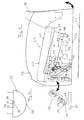
- the partially shown seating / reclining furniture according to FIG. 1 is concerned a chair with two side parts 42, a backrest 46 and a seat part 43, which has a seat frame 44 and a seat cushion 45, through which a seat 47 is defined.
- the seat part 43 is approximately parallel to the Seat 47 extending plane displaceable by means of a linear guide, which enables seat depth adjustment.
- This seat depth adjustment is not the subject of this invention, so that the intended Mechanics and motor skills are not explained in detail.
- the armchair or one of the side parts 42 Seat part 43 and the backrest 46 comprehensive assembly of the chair as a whole around a horizontal, perpendicular to the side parts 42 Axis tiltable, as shown by the one drawn in the lower rear area Double arrow is indicated.
- Adjusting the armchair can be achieved, for example, that in the front and rear Area each a drive unit is arranged with which the armchair can be raised and lowered in the respective area.
- the intended mechanics and motor skills are not the subject of this invention and is only explained as far below as it is for understanding the invention is required.
- a dashed line Box 14 symbolizes the following simply as a drive unit 14 of the armchair or the assembly is called.
- Support arms 48 which are attached to the cross members 49, serve among other things to support a motor, not shown, for seat depth adjustment of the seat part 43.
- the armchair further comprises a footrest 12 which is fitted with scissors 51 is connected to the seat frame 44 of the seat part 43.
- a footrest 12 which is fitted with scissors 51 is connected to the seat frame 44 of the seat part 43.
- one does not extend in front of the front cross member 49 shown means connected to the seat frame 44 drive shaft 61, which with a drive unit shown only schematically in Fig. 1 16 can be rotated in the form of an electric motor.
- Via a lever arrangement 62 which is rotatably connected to the drive shaft 61 and on the scissor fitting 51 is articulated by turning the drive shaft 61 the footrest 12 regardless of a movement of the seat part 43 and the assembly, which is adjustable as a whole, moves relative to the seat part 43, i.e. extended and retracted.
- the drive unit 16, the drive shaft 61, the lever arrangement 62 and the scissors fitting 51 are together with the seat part 43 when adjusting the seat depth is movable, so that with the same rotational position Drive shaft 61, the relative position between the seat part 43 and the footrest 12 is not changed by a seat depth adjustment.
- the footrest 12 is both fully retracted in FIG. 1 Rest position, in which a support surface 12a is substantially perpendicular extends to the lower edges 42a of the side parts 42, as well as in one partially extended intermediate position shown.
- the armchair or the above-mentioned assembly as a whole by actuation the drive unit 14 is tilted forward, then the footrest bumps 12 with its lower end to an obstacle 24, which is for example, around the feet of a person sitting in an armchair can act.
- the footrest 12 shows a contact arrangement which includes a pressure-sensitive element 18 and comprises a contact element 26.
- the contact arrangement is not only for movements the footrest 12 by adjusting the armchair or the assembly done as a whole, but also with independent, by the drive unit 16 caused movements of the footrest 12 relative to the Seat part 43 effective, i.e. when retracting and extending the footrest 12.
- the pressure-sensitive element 18 is a silicone switching strip, which has at least one pressure-sensitive surface 32 and extends over the entire width of the footrest 12.
- the contact element 26 is designed as a strip or bar with a semicircular cross section, which also extends over the entire width of the footrest 12.
- the switching strip is in the area of the central axis M of the contact element 26 arranged.
- the contact element 26 is used to transmit pressure from an obstacle, on which the footrest 12 bumps during an adjustment movement pressure-sensitive element 18.
- the contact element 26 is designed such that on one of the curved surface of the contact element 26 formed contact side 28 applied pressure on the pressure sensitive Area 32 of the element 18 is transferred.
- the contact element 26 consists of a composite or molded foam with a relatively high hardness and is glued to the element 18.
- the switching strip is via a signal line 52 shown in dashed lines in FIG. 1 18 connected to a central control unit 22 of the chair, which also via signal lines 53, 63 to the drive units 16, 14 is connected.
- Utilities or utilities to supply power to the drive units 16, 14, the control unit 22 and the switching strip 18 are in for reasons of clarity Fig. 1 not shown.
- the silicone switching strip 18 is designed such that when exceeded a minimum pressure applied to the pressure sensitive surface 32 the electrical resistance of an arrangement that the switching strip 18 and comprises a resistor connected in series therewith, changes.
- the change in resistance is determined by the control unit 22 detected by means of comparator circuits.
- the control unit 22 sends then predetermined control signals according to their programming the drive units 16, 14. Based on these control signals, e.g. the the footrest 12 associated drive unit 16 turned off and the Drive unit 14 causes the chair to lift as a whole. hereby contact element 26 becomes disengaged from obstacle 24 brought. Furthermore, for example, on a not shown Control unit of the chair shows a visual warning or fault signal.
- the one required to cause an appropriate change in resistance Minimum pressure is a characteristic quantity of the respective pressure sensitive Element 18.
- An advantage of the semicircular configuration of the contact element 26 is that forces that are large, symmetrical with respect to element 18 Angular range of about 120 ° exerted on the contact side 28 are transferred to the pressure-sensitive surface 32 of the element 18 be and so a switching signal to interrupt the movement of the Can trigger footrest 12 if the respective minimum pressure is exceeded becomes.
- the protective function according to the invention can also be used in conjunction with others adjustable facilities of any functional furniture used with, for example, electromotive bed fittings and movable, in particular, lowerable facilities for standing up aids.
- Silicone switching strip 18 can also be any other pressure sensitive Devices such as electronic pressure sensors and Print mats are used. Furthermore, instead of a single pressure sensitive strip e.g. several arranged side by side Individual elements are provided. For example, it is possible to provide individual switching elements when hitting an obstacle operated mechanically, e.g. through a rotatably mounted Rocker ledge.
Landscapes
- Health & Medical Sciences (AREA)
- Dentistry (AREA)
- General Health & Medical Sciences (AREA)
- Chairs For Special Purposes, Such As Reclining Chairs (AREA)
- Chair Legs, Seat Parts, And Backrests (AREA)
- Transition And Organic Metals Composition Catalysts For Addition Polymerization (AREA)
- Push-Button Switches (AREA)
- Force Measurement Appropriate To Specific Purposes (AREA)
Description
- Fig. 1
- eine vereinfachte Darstellung eines Sitz-/Liegemöbels gemäß einer Ausführungsform der Erfindung in einer Seitenansicht, und
- Fig. 2
- eine Kontaktanordnung des Sitz-/Liegemöbels von Fig. 1 in einer vergrößerten Darstellung.
- 12
- verstellbare Einrichtung, Fußstütze
- 14
- Antriebseinheit
- 16
- Antriebseinheit
- 18
- drucksensitives Element
- 22
- Steuereinheit
- 24
- Hindernis
- 25
- Träger
- 26
- Kontaktelement
- 28
- Kontaktseite
- 32
- druckempfindliche Fläche
- 41
- Boden
- 42
- Seitenteil
- 42a
- Unterkante
- 43
- Sitzteil
- 44
- Sitzrahmen
- 45
- Sitzpolster
- 46
- Rückenlehne
- 47
- Sitzfläche
- 48
- Tragarm
- 49
- Querträger
- 51
- Scherenbeschlag
- 52
- Signalleitung
- 53
- Signalleitung
- 54
- Seitenplatte
- 61
- Antriebswelle
- 62
- Hebelanordnung
- 63
- Signalleitung
- M
- Mittelachse
Claims (13)
- Sitz-/Liegemöbel mit zumindest einer Einrichtung (12), insbesondere einer Fußstütze, die durch wenigstens eine elektrisch betreibbare Antriebseinheit (14, 16) verstellbar ist und zumindest ein drucksensitives Element (18) aufweist, dadurch gekennzeichnet, daß die Antriebseinheit (14, 16) und das drucksensitive Element (18) mit einer Steuereinheit (22) verbunden sind und die Antriebseinheit (14, 16) bei Überschreiten eines auf das drucksensitive Element (18) von einem Hindernis (24) ausgeübten Mindestdrucks von der Steuereinheit (22) zur Unterbrechung der Bewegung der verstellbaren Einrichtung (12) ansteuerbar ist.
- Sitz-/Liegemöbel nach Anspruch 1,
dadurch gekennzeichnet, daß das drucksensitive Element (18) mit einem Kontaktelement (26) gekoppelt ist, über das auf eine Kontaktseite (28) des Kontaktelementes (26) ausgeübter Druck auf das drucksensitive Element (18) übertragbar ist. - Sitz-/ Liegemöbel nach Anspruch 2,
dadurch gekennzeichnet, daß zumindest eine druckempfindliche Fläche (32) des drucksensitiven Elementes (18) vollständig von dem Kontaktelemente (26) bedeckt ist. - Sitz-/Liegemöbel nach Anspruch 2 oder 3,
dadurch gekennzeichnet, daß die Kontaktseite (28) des Kontaktelementes (26) größer, insbesondere wesentlich größer ist als eine druckempfindliche Fläche (32) des drucksensitiven Elementes (18). - Sitz-/Liegemöbel nach zumindest einem der Ansprüche 2 bis 4,
dadurch gekennzeichnet, daß die Kontaktseite (28) des bevorzugt streifen- oder leistenförmigen Kontaktelementes (26) abgerundet ist und vorzugsweise einen etwa halbkreisförmigen Querschnitt aufweist, wobei bevorzugt das drucksensitive Element (18) mit einer der Kontaktseite (28) gegenüberliegenden geraden Seite des Kontaktelementes (26) gekoppelt ist. - Sitz-/Liegemöbel nach zumindest einem der Ansprüche 2 bis 5,
dadurch gekennzeichnet, daß das Kontaktelement (26) über oder auf das drucksensitive Element (18) geklebt ist. - Sitz- /Liegemöbel nach zumindest einem der Ansprüche 2 bis 6,
dadurch gekennzeichnet, daß das Kontaktelement (26) aus Schaumstoff, insbesondere aus einem Verbund- oder Formschaum, hergestellt ist. - Sitz-/Liegemöbel nach zumindest einem der vorhergehenden Ansprüche,
dadurch gekennzeichnet, daß die verstellbare Einrichtung eine ein- und ausfahrbare Fußstütze (12) ist, wobei bevorzugt das drucksensitive Element (18) an einem im eingefahrenen Zustand im wesentlichen nach unten und im ausgefahrenen Zustand im wesentlichen nach vorn weisenden Bereich der Fußstütze (12) angebracht ist. - Sitz-/Liegemöbel nach zumindest einem der vorhergehenden Ansprüche,
dadurch gekennzeichnet, daß das drucksensitive Element (18) derart ausgebildet ist, daß eine bei Überschreiten des Mindestdrucks eintretende Änderung des elektrischen Widerstandes des drucksensitiven Elementes (18) durch die Steuereinheit (22) insbesondere mittels einer Komparatorschaltung detektierbar ist. - Sitz-/Liegemöbel nach zumindest einem der vorhergehenden Ansprüche,
dadurch gekennzeichnet, daß das drucksensitive Element (18) streifenförmig ausgebildet und insbesondere in Form eines Silikonschaltstreifens vorgesehen ist. - Sitz-/Liegemöbel nach zumindest einem der vorhergehenden Ansprüche,
dadurch gekennzeichnet, daß die verstellbare Einrichtung (12) an einer durch die Antriebseinheit (14) bewegbaren Baugruppe angebracht und durch Bewegen der Baugruppe verstellbar ist, wobei bevorzugt die Baugruppe zumindest ein Sitz-/Liegeteil (43) und eine Rückenlehne (46) umfaßt. - Sitz-/Liegemöbel nach Anspruch 11,
dadurch gekennzeichnet, daß die Baugruppe durch die Antriebseinheit (14) anhebbar und absenkbar und/oder verkippbar ist und die Antriebseinheit (14) bei Überschreiten des Mindestdrucks von der Steuereinheit (22) zum Anheben der Baugruppe zumindest in einem vorderen Bereich des Sitz-/Liegemöbels ansteuerbar ist. - Sitz-/Liegemöbel nach Anspruch 11 oder 12,
dadurch gekennzeichnet, daß die verstellbare Einrichtung (12) relativ zu der Baugruppe durch eine separate Antriebseinheit (16) bewegbar ist, die bevorzugt bei Überschreiten des Mindestdrucks von der Steuereinheit (22) abschaltbar ist.
Applications Claiming Priority (2)
| Application Number | Priority Date | Filing Date | Title |
|---|---|---|---|
| DE29917281U | 1999-10-01 | ||
| DE29917281U DE29917281U1 (de) | 1999-10-01 | 1999-10-01 | Sitz-/Liegemöbel |
Publications (2)
| Publication Number | Publication Date |
|---|---|
| EP1088499A1 EP1088499A1 (de) | 2001-04-04 |
| EP1088499B1 true EP1088499B1 (de) | 2004-05-12 |
Family
ID=8079693
Family Applications (1)
| Application Number | Title | Priority Date | Filing Date |
|---|---|---|---|
| EP00121610A Expired - Lifetime EP1088499B1 (de) | 1999-10-01 | 2000-10-02 | Sitz-/Liegemöbel |
Country Status (3)
| Country | Link |
|---|---|
| EP (1) | EP1088499B1 (de) |
| AT (1) | ATE266337T1 (de) |
| DE (2) | DE29917281U1 (de) |
Families Citing this family (3)
| Publication number | Priority date | Publication date | Assignee | Title |
|---|---|---|---|---|
| DE20016789U1 (de) | 2000-09-28 | 2000-12-14 | Kemmann & Koch GmbH & Co. KG, 42551 Velbert | Möbelbeschlag für ein ausziehbares Möbelteil |
| CN103932521B (zh) * | 2014-05-14 | 2017-01-11 | 锐迈机械科技(吴江)有限公司 | 一种活动沙发电动机械伸展装置 |
| TWI892444B (zh) * | 2024-02-02 | 2025-08-01 | 酷碼科技股份有限公司 | 動態載體安全防護系統及方法 |
Family Cites Families (3)
| Publication number | Priority date | Publication date | Assignee | Title |
|---|---|---|---|---|
| JPS6094840A (ja) * | 1983-10-31 | 1985-05-28 | Nissan Shatai Co Ltd | 電動シ−トの安全停止装置 |
| US5931532A (en) * | 1997-02-03 | 1999-08-03 | Kemmerer; Kenneth | Lift recliner chair with safety system |
| GB2343371B (en) * | 1998-11-03 | 2000-09-27 | Ulland Islwyn Watkins | Control of powered furniture |
-
1999
- 1999-10-01 DE DE29917281U patent/DE29917281U1/de not_active Expired - Lifetime
-
2000
- 2000-10-02 EP EP00121610A patent/EP1088499B1/de not_active Expired - Lifetime
- 2000-10-02 AT AT00121610T patent/ATE266337T1/de active
- 2000-10-02 DE DE50006387T patent/DE50006387D1/de not_active Expired - Lifetime
Also Published As
| Publication number | Publication date |
|---|---|
| ATE266337T1 (de) | 2004-05-15 |
| DE50006387D1 (de) | 2004-06-17 |
| EP1088499A1 (de) | 2001-04-04 |
| DE29917281U1 (de) | 1999-12-09 |
Similar Documents
| Publication | Publication Date | Title |
|---|---|---|
| DE10209234B4 (de) | Fahrzeugsitz mit Unterschenkelstütze | |
| DE69601996T2 (de) | Fahrzeugsitz und system zur steuerung desselben | |
| DE60108308T2 (de) | Flugzeugsitz mit verstellbaren Bein- und Fussstütze | |
| DE19853156B4 (de) | Sitz | |
| DE102019203863B4 (de) | Höhenverstellvorrichtung für einen Fahrzeugsitz | |
| DE69126303T2 (de) | Kraftfahrzeugsitz für behinderte | |
| DE3843624A1 (de) | Steuereinrichtung fuer eine kopfstuetze | |
| DE3739752A1 (de) | Sitz fuer ein fahrzeug, flugzeug oder dergleichen | |
| EP1492703A1 (de) | Sitz, insbesondere fluggastsitz | |
| DE69101409T2 (de) | Zentralisierte Steuervorrichtung für Fahrzeugsitze. | |
| EP1223835B1 (de) | Sitz | |
| EP0084107B1 (de) | Elektrisch verstellbarer Fahrzeugsitz | |
| EP1360109A1 (de) | Fahrzeugsitz mit innerhalb einer räumlichen begrenzung einstellbaren sitzkomponenten | |
| DE60202235T2 (de) | Sitz insbesondere für Flugzeuge bestehend aus einem verstellbaren Sitzteil und einer Rückenlehne | |
| EP1360086A1 (de) | Sitz, insbesondere Fahrzeugsitz, vorzugsweise Fluggastsitz | |
| DE19614523A1 (de) | Sitzanordnung für Fahrzeuge mit einer Insassen-Erfassungseinrichtung | |
| EP1088499A1 (de) | Sitz-/Liegemöbel | |
| DE102018120643A1 (de) | Schwenkbares zusammengesetztes mechanisches verkleidungsausgabeverbindungssystem für oberschenkelausschub | |
| DE4012578A1 (de) | Elektromotorische verstellvorrichtung fuer eine rueckenlehne eines fahrzeugsitzes | |
| EP1754426B1 (de) | Sitzmöbel mit ausziehbarer Beinauflage | |
| DE881005C (de) | Einstellbarer Sitz fuer Kraftfahrzeuge | |
| DE2609029A1 (de) | Schubmaststapler | |
| EP1078808A1 (de) | Verstelleinrichtung für ein verstellbares Sitzteil eines Kraftfahrzeugsitzes | |
| DE3238901A1 (de) | Sicherheitseinrichtung fuer fahrzeuge, insbesondere personenkraftfahrzeuge | |
| DE102025136332A1 (de) | Fahrzeugsitz sowie Sitzanordnung in einem Fahrzeug |
Legal Events
| Date | Code | Title | Description |
|---|---|---|---|
| PUAI | Public reference made under article 153(3) epc to a published international application that has entered the european phase |
Free format text: ORIGINAL CODE: 0009012 |
|
| AK | Designated contracting states |
Kind code of ref document: A1 Designated state(s): AT BE CH CY DE DK ES FI FR GB GR IE IT LI LU MC NL PT SE |
|
| AX | Request for extension of the european patent |
Free format text: AL;LT;LV;MK;RO;SI |
|
| AKX | Designation fees paid | ||
| 17P | Request for examination filed |
Effective date: 20010515 |
|
| RBV | Designated contracting states (corrected) |
Designated state(s): AT BE CH CY DE DK ES FI FR GB GR IE IT LI LU MC NL PT SE |
|
| GRAP | Despatch of communication of intention to grant a patent |
Free format text: ORIGINAL CODE: EPIDOSNIGR1 |
|
| GRAS | Grant fee paid |
Free format text: ORIGINAL CODE: EPIDOSNIGR3 |
|
| GRAA | (expected) grant |
Free format text: ORIGINAL CODE: 0009210 |
|
| AK | Designated contracting states |
Kind code of ref document: B1 Designated state(s): AT BE CH CY DE DK ES FI FR GB GR IE IT LI LU MC NL PT SE |
|
| PG25 | Lapsed in a contracting state [announced via postgrant information from national office to epo] |
Ref country code: IT Free format text: LAPSE BECAUSE OF FAILURE TO SUBMIT A TRANSLATION OF THE DESCRIPTION OR TO PAY THE FEE WITHIN THE PRESCRIBED TIME-LIMIT;WARNING: LAPSES OF ITALIAN PATENTS WITH EFFECTIVE DATE BEFORE 2007 MAY HAVE OCCURRED AT ANY TIME BEFORE 2007. THE CORRECT EFFECTIVE DATE MAY BE DIFFERENT FROM THE ONE RECORDED. Effective date: 20040512 Ref country code: IE Free format text: LAPSE BECAUSE OF FAILURE TO SUBMIT A TRANSLATION OF THE DESCRIPTION OR TO PAY THE FEE WITHIN THE PRESCRIBED TIME-LIMIT Effective date: 20040512 Ref country code: FI Free format text: LAPSE BECAUSE OF FAILURE TO SUBMIT A TRANSLATION OF THE DESCRIPTION OR TO PAY THE FEE WITHIN THE PRESCRIBED TIME-LIMIT Effective date: 20040512 Ref country code: CY Free format text: LAPSE BECAUSE OF FAILURE TO SUBMIT A TRANSLATION OF THE DESCRIPTION OR TO PAY THE FEE WITHIN THE PRESCRIBED TIME-LIMIT Effective date: 20040512 |
|
| REG | Reference to a national code |
Ref country code: GB Ref legal event code: FG4D Free format text: NOT ENGLISH |
|
| REG | Reference to a national code |
Ref country code: CH Ref legal event code: EP |
|
| REG | Reference to a national code |
Ref country code: IE Ref legal event code: FG4D Free format text: GERMAN |
|
| REF | Corresponds to: |
Ref document number: 50006387 Country of ref document: DE Date of ref document: 20040617 Kind code of ref document: P |
|
| GBT | Gb: translation of ep patent filed (gb section 77(6)(a)/1977) |
Effective date: 20040712 |
|
| PG25 | Lapsed in a contracting state [announced via postgrant information from national office to epo] |
Ref country code: GR Free format text: LAPSE BECAUSE OF FAILURE TO SUBMIT A TRANSLATION OF THE DESCRIPTION OR TO PAY THE FEE WITHIN THE PRESCRIBED TIME-LIMIT Effective date: 20040812 Ref country code: DK Free format text: LAPSE BECAUSE OF FAILURE TO SUBMIT A TRANSLATION OF THE DESCRIPTION OR TO PAY THE FEE WITHIN THE PRESCRIBED TIME-LIMIT Effective date: 20040812 Ref country code: SE Free format text: LAPSE BECAUSE OF FAILURE TO SUBMIT A TRANSLATION OF THE DESCRIPTION OR TO PAY THE FEE WITHIN THE PRESCRIBED TIME-LIMIT Effective date: 20040812 |
|
| PG25 | Lapsed in a contracting state [announced via postgrant information from national office to epo] |
Ref country code: ES Free format text: LAPSE BECAUSE OF FAILURE TO SUBMIT A TRANSLATION OF THE DESCRIPTION OR TO PAY THE FEE WITHIN THE PRESCRIBED TIME-LIMIT Effective date: 20040823 |
|
| PG25 | Lapsed in a contracting state [announced via postgrant information from national office to epo] |
Ref country code: LU Free format text: LAPSE BECAUSE OF NON-PAYMENT OF DUE FEES Effective date: 20041002 |
|
| PG25 | Lapsed in a contracting state [announced via postgrant information from national office to epo] |
Ref country code: MC Free format text: LAPSE BECAUSE OF NON-PAYMENT OF DUE FEES Effective date: 20041031 |
|
| ET | Fr: translation filed | ||
| REG | Reference to a national code |
Ref country code: IE Ref legal event code: FD4D |
|
| PLBE | No opposition filed within time limit |
Free format text: ORIGINAL CODE: 0009261 |
|
| STAA | Information on the status of an ep patent application or granted ep patent |
Free format text: STATUS: NO OPPOSITION FILED WITHIN TIME LIMIT |
|
| 26N | No opposition filed |
Effective date: 20050215 |
|
| PG25 | Lapsed in a contracting state [announced via postgrant information from national office to epo] |
Ref country code: PT Free format text: LAPSE BECAUSE OF NON-PAYMENT OF DUE FEES Effective date: 20041012 |
|
| REG | Reference to a national code |
Ref country code: FR Ref legal event code: PLFP Year of fee payment: 16 |
|
| REG | Reference to a national code |
Ref country code: FR Ref legal event code: PLFP Year of fee payment: 17 |
|
| REG | Reference to a national code |
Ref country code: FR Ref legal event code: PLFP Year of fee payment: 18 |
|
| REG | Reference to a national code |
Ref country code: FR Ref legal event code: PLFP Year of fee payment: 19 |
|
| PGFP | Annual fee paid to national office [announced via postgrant information from national office to epo] |
Ref country code: NL Payment date: 20191129 Year of fee payment: 20 |
|
| PGFP | Annual fee paid to national office [announced via postgrant information from national office to epo] |
Ref country code: FR Payment date: 20191129 Year of fee payment: 20 Ref country code: BE Payment date: 20191129 Year of fee payment: 20 |
|
| PGFP | Annual fee paid to national office [announced via postgrant information from national office to epo] |
Ref country code: CH Payment date: 20191219 Year of fee payment: 20 Ref country code: AT Payment date: 20191202 Year of fee payment: 20 |
|
| PGFP | Annual fee paid to national office [announced via postgrant information from national office to epo] |
Ref country code: GB Payment date: 20191129 Year of fee payment: 20 Ref country code: DE Payment date: 20191230 Year of fee payment: 20 |
|
| REG | Reference to a national code |
Ref country code: DE Ref legal event code: R071 Ref document number: 50006387 Country of ref document: DE |
|
| REG | Reference to a national code |
Ref country code: NL Ref legal event code: MK Effective date: 20201001 |
|
| REG | Reference to a national code |
Ref country code: CH Ref legal event code: PL |
|
| REG | Reference to a national code |
Ref country code: GB Ref legal event code: PE20 Expiry date: 20201001 |
|
| REG | Reference to a national code |
Ref country code: BE Ref legal event code: MK Effective date: 20201002 |
|
| PG25 | Lapsed in a contracting state [announced via postgrant information from national office to epo] |
Ref country code: GB Free format text: LAPSE BECAUSE OF EXPIRATION OF PROTECTION Effective date: 20201001 |
|
| REG | Reference to a national code |
Ref country code: AT Ref legal event code: MK07 Ref document number: 266337 Country of ref document: AT Kind code of ref document: T Effective date: 20201002 |