EP1087153B1 - Dispositif pour l'augmentation de l'amortissement - Google Patents
Dispositif pour l'augmentation de l'amortissement Download PDFInfo
- Publication number
- EP1087153B1 EP1087153B1 EP00118064A EP00118064A EP1087153B1 EP 1087153 B1 EP1087153 B1 EP 1087153B1 EP 00118064 A EP00118064 A EP 00118064A EP 00118064 A EP00118064 A EP 00118064A EP 1087153 B1 EP1087153 B1 EP 1087153B1
- Authority
- EP
- European Patent Office
- Prior art keywords
- piston
- flow
- spring
- damper
- hydraulic
- Prior art date
- Legal status (The legal status is an assumption and is not a legal conclusion. Google has not performed a legal analysis and makes no representation as to the accuracy of the status listed.)
- Expired - Lifetime
Links
Images


Classifications
-
- F—MECHANICAL ENGINEERING; LIGHTING; HEATING; WEAPONS; BLASTING
- F16—ENGINEERING ELEMENTS AND UNITS; GENERAL MEASURES FOR PRODUCING AND MAINTAINING EFFECTIVE FUNCTIONING OF MACHINES OR INSTALLATIONS; THERMAL INSULATION IN GENERAL
- F16F—SPRINGS; SHOCK-ABSORBERS; MEANS FOR DAMPING VIBRATION
- F16F9/00—Springs, vibration-dampers, shock-absorbers, or similarly-constructed movement-dampers using a fluid or the equivalent as damping medium
- F16F9/32—Details
- F16F9/58—Stroke limiting stops, e.g. arranged on the piston rod outside the cylinder
- F16F9/585—Stroke limiting stops, e.g. arranged on the piston rod outside the cylinder within the cylinder, in contact with working fluid
-
- F—MECHANICAL ENGINEERING; LIGHTING; HEATING; WEAPONS; BLASTING
- F16—ENGINEERING ELEMENTS AND UNITS; GENERAL MEASURES FOR PRODUCING AND MAINTAINING EFFECTIVE FUNCTIONING OF MACHINES OR INSTALLATIONS; THERMAL INSULATION IN GENERAL
- F16F—SPRINGS; SHOCK-ABSORBERS; MEANS FOR DAMPING VIBRATION
- F16F9/00—Springs, vibration-dampers, shock-absorbers, or similarly-constructed movement-dampers using a fluid or the equivalent as damping medium
- F16F9/32—Details
- F16F9/48—Arrangements for providing different damping effects at different parts of the stroke
- F16F9/49—Stops limiting fluid passage, e.g. hydraulic stops or elastomeric elements inside the cylinder which contribute to changes in fluid damping
Definitions
- the invention relates to a device for increasing the damping at the end of hydraulic vibration dampers with hydraulic means wherein the flow cross-section of the damper interior in two work spaces dividing damper piston is reduced by partially covering the inflow and wherein the inflow surface consists of a plurality of non-interconnected Einzelzuström vom.
- Such devices are also hydraulic Switzerlandanschlag or called hydraulic pressure stop.
- train or pressure stops are provided. Especially with vibration dampers on motor vehicles, it has proven to be advantageous to design these train or pressure stops by hydraulic means. Usually Therefore, it is provided that the inflow cross sections of the working piston be partially covered at the end of the stroke by means of discs or bells. The cover or cover bells are supported by a spring, so that at the end of the stroke increased damping occurs.
- the invention is based on the object, the device according to the preamble of To further develop claim 1 so that the stop movement controlled can be controlled.
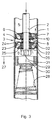
- Hydraulic vibration dampers especially for motor vehicles, have a damper tube 1, in which oscillates a piston rod 2 dips. At the dipping End of the piston rod 2 is a damper piston 3 with at least one working piston 4 mounted, which filled with damping fluid interior of the Damper tube 1 divided into two working spaces 5, 6.
- Spring washers 7, 8 or Spring disk packages act as valves in each case one working direction of the working piston 4 and produce the desired damping force.
- These spring washers 7, 8 each cover the outlet of arranged in the working piston 4 flow channels 9, 10 off.
- the number and shape of the flow channels 9, 10 are the same and lie on a common diameter. They alternate here and differ in that they are inclined in different directions to the piston rod axis run. This makes it possible that the spring washers 7, 8 the cover each inside outflow cross section of the flow channels 9, 10, wherein the respective outer inflow cross sections remain open.
- Other forms of working piston with other, for example finger-shaped spring washers can be used in the same way.
- a hydraulic Ceintz is shown. This is done by the piston rod 2 piston rod side next to the working piston 4 an inflow piston 11, which is constructed in the same way as the working piston 4. Also on Zuströmkolben 11 are on both sides of the inner outflow openings of the flow channels 12, 13 covered by spring washers 14, 15. The the working piston 4 facing away Spring washer 14 of the inflow piston 11, however, has openings 16 on.
- a piston rod outlet side arranged compression spring 17 is supported on the piston rod outside on the damper tube 1 from. It carries at its other end a cover plate 18th
- Fig. 1 the working position of the piston rod 2 and damper piston 3 is shown, i.e. the vibration damper operates in normal operation.
- Fig. 1 shows the Naturalströmmother the damping fluid in the pulling direction, so when extending the piston rod 2 from the damper tube 1.
- the upper working space 5 opposite the lower working space 6 an overpressure, which flows through the Damping fluid through the damper piston 3 from the upper working chamber 5 in the lower working space 6 leads.
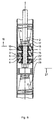
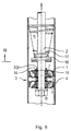
- a hydraulic pressure stop according to the invention is shown in Figs. 3 and 4.
- kolbenstangenend herb under the working piston 4 an inflow piston 21 arranged with different flow channels 22, 23. Both flow channels 22, 23 are in turn covered by spring washers 24, 25 in the interior.
- an end area is 27, here for the hydraulic pressure stop, determined by a compression spring 28, located at the the piston rod 2 facing away from the wall of the damper tube 1 at this is supported.
- a Abdeckglocke 29 attached, which has a recess 30 into which the fastening nut 31 for holding the damper piston 3 on the piston rod 2 dip can.
- the effect of the hydraulic pressure stop according to FIG. 7 corresponds to the mode of action of the hydraulic pressure stop according to FIG. 4, as soon as the damper piston 3 enters the corresponding end portion 27. Since the inflow openings of the Throughflow 22 of the inflow piston 21 are closed, flows through the Damping fluid, the flow channels 23, overcoming the through Spring washer 24 caused flow resistance. After distribution in the space 32 is then the working piston 4, overcoming the through Spring washer 7 caused flow resistance flowed through to thereafter to be able to flow through the inflow piston 11 without special flow resistance.
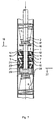
- FIG. 8 The representation of a Buchanschlages invention according to FIG. 8 corresponds to the Representation of FIG. 1.
- an axially yielding spring 33 the - like shown - may be formed as a corrugated spring.
- the distance 34 decreases continuously, until it reduces to zero at the latest, as soon as the compression spring 17 to block drove.
- the reduction of the distance 34 as a function of the compression the compression spring 17 is dependent on the design of the compression spring 17 and the spring 33. The distance 34 can thus already reach zero before the compression spring 17 is moved to block.
Landscapes
- Engineering & Computer Science (AREA)
- General Engineering & Computer Science (AREA)
- Mechanical Engineering (AREA)
- Fluid-Damping Devices (AREA)
- Types And Forms Of Lifts (AREA)
Claims (6)
- Dispositif pour renforcer l'amortissement dans la région terminale (19, 27) d'amortisseurs hydrauliques par des moyens hydrauliques, dans lequel la section de passage à travers le piston (3) divisant l'espace interne de l'amortisseur en deux chambres de travail, est réduite par obturation partielle de la surface d'admission, la surface d'admission étant constituée de plusieurs surfaces d'admission distinctes qui ne sont pas reliées entre elles, une ou plusieurs des surfaces d'admission distinctes étant complètement obturées, et l'étanchéité résultant d'une plaque d'obturation (18) disposée à l'extrémité d'un ressort (17, 28), ou d'une cloche d'obturation (29) maintenue de manière correspondante, caractérisé en ce que, entre la plaque d'obturation (18) ou la cloche d'obturation (29) et le piston d'admission (11, 21), est agencé un ressort (33) flexible dans le sens axial.
- Dispositif selon la revendication 1, caractérisé en ce que les surfaces d'admission distinctes sont agencées sur au moins deux régions annulaires du piston (3) de l'amortisseur, disposées l'une à l'intérieur de l'autre, sans contact.
- Dispositif selon la revendication 2, caractérisé en ce que les régions annulaires sont séparées l'une de l'autre par des arêtes ou des découpes circulaires.
- Dispositif selon une ou plusieurs des revendications 1 à 3, caractérisé en ce que le piston d'amortisseur (3) présente un ou plusieurs pistons d'admission (11, 21) en plus d'un piston de travail (4).
- Dispositif selon la revendication 4, caractérisé en ce que le/les pistons d'admission (11,21) présentent des surfaces d'admission distinctes.
- Dispositif selon la revendication 4 ou 5, caractérisé en ce que les canaux de passage (13, 23) qui ne peuvent être fermés du/des pistons d'admission (11, 21) sont obturés du côté de la face de sortie par des disques de ressort (15, 24).
Applications Claiming Priority (2)
| Application Number | Priority Date | Filing Date | Title |
|---|---|---|---|
| DE19945632 | 1999-09-23 | ||
| DE19945632A DE19945632B4 (de) | 1999-09-23 | 1999-09-23 | Vorrichtung zur Erhöhung der Dämpfung |
Publications (2)
| Publication Number | Publication Date |
|---|---|
| EP1087153A1 EP1087153A1 (fr) | 2001-03-28 |
| EP1087153B1 true EP1087153B1 (fr) | 2005-04-27 |
Family
ID=7923055
Family Applications (1)
| Application Number | Title | Priority Date | Filing Date |
|---|---|---|---|
| EP00118064A Expired - Lifetime EP1087153B1 (fr) | 1999-09-23 | 2000-08-23 | Dispositif pour l'augmentation de l'amortissement |
Country Status (5)
| Country | Link |
|---|---|
| US (1) | US6681906B1 (fr) |
| EP (1) | EP1087153B1 (fr) |
| BR (1) | BR0004339A (fr) |
| DE (2) | DE19945632B4 (fr) |
| ES (1) | ES2237369T3 (fr) |
Families Citing this family (14)
| Publication number | Priority date | Publication date | Assignee | Title |
|---|---|---|---|---|
| DE10222940C1 (de) * | 2002-05-24 | 2003-07-31 | Zf Sachs Ag | Schwingungsdämpfer mit einem hydraulischen Druckanschlag |
| DE102004035613A1 (de) * | 2004-07-22 | 2006-03-16 | Stabilus Gmbh | Gasfeder mit Endlagendämpfung |
| JP4753238B2 (ja) * | 2005-09-09 | 2011-08-24 | ヤマハ発動機株式会社 | 油圧緩衝器 |
| US8162112B2 (en) | 2007-02-09 | 2012-04-24 | Competition Tire East | Methods and apparatus for protecting a shock absorber from bottoming |
| CA2639822A1 (fr) * | 2007-09-26 | 2009-03-26 | Bombardier Recreational Products Inc. | Amortisseur sensible a la position |
| US8297418B2 (en) * | 2008-06-05 | 2012-10-30 | Tenneco Automotive Operating Company Inc. | Nested check high speed valve |
| DE102009012515B4 (de) | 2009-03-10 | 2018-11-22 | Man Truck & Bus Ag | Schwingungsdämpfer |
| JP5936128B2 (ja) | 2012-12-26 | 2016-06-15 | Kyb株式会社 | 緩衝器 |
| US9091320B1 (en) * | 2014-01-08 | 2015-07-28 | Thyssenkrupp Bilstein Of America, Inc. | Multi-stage shock absorber |
| ES2818626T3 (es) * | 2014-10-01 | 2021-04-13 | Beijingwest Ind Co Ltd | Conjunto de amortiguador |
| FR3049222B1 (fr) * | 2016-03-25 | 2018-04-13 | Peugeot Citroen Automobiles Sa | Systeme de suspension hydraulique d'un vehicule |
| FR3049502B1 (fr) * | 2016-03-31 | 2018-04-20 | Peugeot Citroen Automobiles Sa | Vehicule a systeme de suspension hydraulique |
| DE102019213913A1 (de) | 2019-09-12 | 2021-03-18 | Thyssenkrupp Ag | Hydraulischer Schwingungsdämpfer mit einem Zug- und einem Druckanschlag |
| CN113958649A (zh) * | 2021-10-31 | 2022-01-21 | 成都九鼎科技(集团)有限公司 | 减振器液压缓冲组件及渐变式行程调节减振器 |
Family Cites Families (17)
| Publication number | Priority date | Publication date | Assignee | Title |
|---|---|---|---|---|
| US1445615A (en) * | 1920-11-24 | 1923-02-13 | Jeffrey T Ferres | Shock absorber |
| US2355491A (en) * | 1943-03-22 | 1944-08-08 | Monroe Auto Equipment Co | Hydraulic shock absorber |
| US2456736A (en) * | 1945-01-25 | 1948-12-21 | Gen Motors Corp | Shock absorber |
| US2599477A (en) * | 1950-03-17 | 1952-06-03 | Gabriel Co | Shock absorber |
| GB763557A (en) * | 1954-11-16 | 1956-12-12 | Newtcn & Bennett Ltd | Improvements in or relating to hydraulic shock absorbers |
| US3111201A (en) * | 1961-04-27 | 1963-11-19 | Ford Motor Co | Hydraulic shock absorber |
| DE1249037B (fr) * | 1961-06-02 | 1967-08-31 | ||
| DE1430494B1 (de) * | 1962-01-22 | 1970-04-02 | Carbon Christian Marie Lucien | Hydropneumatischer Einrohr-Stossdaempfer fuer Kraftfahrzeuge |
| DE1505360A1 (de) * | 1965-02-06 | 1970-03-26 | Bourcier De Carbon Christian M | Hydropneumatischer Einrohr-Stossdaempfer fuer Kraftfahrzeuge |
| US4004662A (en) * | 1973-10-16 | 1977-01-25 | Volkswagenwerk Aktiengesellschaft | Shock absorber with different damping effects at different parts of stroke |
| GB1547193A (en) * | 1977-08-15 | 1979-06-06 | Girling Ltd | Telescopic suspension units for vehicles |
| FR2421309A1 (fr) * | 1978-03-29 | 1979-10-26 | Bourcier Carbon Christian | Perfectionnements aux amortisseurs du type monotube |
| DE3500101C1 (de) * | 1985-01-03 | 1986-07-24 | Ford-Werke AG, 5000 Köln | Hydraulischer Zweirohr-Schwingungsdämpfer |
| DE3533387A1 (de) * | 1985-09-19 | 1987-03-26 | Fichtel & Sachs Ag | Zweirohr-schwingungsdaempfer mit hydraulischem druckanschlag |
| DE3623787A1 (de) * | 1986-07-15 | 1988-01-21 | Bauer Fritz & Soehne Ohg | Gasfeder mit endlagendaempfung |
| US5219414A (en) * | 1989-04-24 | 1993-06-15 | Atsugi Unisia Corporation | Variable damping force shock absorber with stroke dependent variation characteristics of damping force |
| US6102170A (en) * | 1998-05-07 | 2000-08-15 | Tenneco Automotive Inc. | Passive anti-roll system |
-
1999
- 1999-09-23 DE DE19945632A patent/DE19945632B4/de not_active Expired - Lifetime
-
2000
- 2000-07-11 US US09/613,779 patent/US6681906B1/en not_active Expired - Lifetime
- 2000-08-23 DE DE50010148T patent/DE50010148D1/de not_active Expired - Lifetime
- 2000-08-23 ES ES00118064T patent/ES2237369T3/es not_active Expired - Lifetime
- 2000-08-23 EP EP00118064A patent/EP1087153B1/fr not_active Expired - Lifetime
- 2000-09-20 BR BR0004339-7A patent/BR0004339A/pt not_active IP Right Cessation
Also Published As
| Publication number | Publication date |
|---|---|
| US6681906B1 (en) | 2004-01-27 |
| ES2237369T3 (es) | 2005-08-01 |
| BR0004339A (pt) | 2001-04-03 |
| DE19945632A1 (de) | 2001-04-26 |
| DE50010148D1 (de) | 2005-06-02 |
| EP1087153A1 (fr) | 2001-03-28 |
| DE19945632B4 (de) | 2005-11-03 |
Similar Documents
| Publication | Publication Date | Title |
|---|---|---|
| EP1152166B2 (fr) | Amortisseur de chocs avec amortissement dépendant de l'amplitude | |
| EP1767810B1 (fr) | Dispositf de valve d'amortisseur ayant une évolution progressive de la force d'amortissement | |
| DE19749356B4 (de) | Zweistufiger Stoßdämpfer mit hubabhängiger Dämpfung | |
| EP1788276B1 (fr) | Amortisseur de vibrations avec une force d'amortissement dépendant de l'amplitude | |
| EP0715091B1 (fr) | Amortisseur de vibrations réglable | |
| EP0926384B1 (fr) | Piston pour un amortisseur de vibrations hydraulique | |
| EP1087153B1 (fr) | Dispositif pour l'augmentation de l'amortissement | |
| DE2229945C2 (de) | Pralldämpfer für Stoßstangen von Kraftfahrzeugen | |
| EP1775495A2 (fr) | Amortisseur de vibrations avec force d'amortissement réglable | |
| DE102005008162B3 (de) | Dämpfventil | |
| DE202009004752U1 (de) | Dämpfer für Möbel | |
| DE3902882A1 (de) | Hydraulisch blockierbare gasfeder | |
| DE2825524C2 (fr) | ||
| DE2218952A1 (de) | Hydraulischer aufpralldaempfer | |
| DE19738617C2 (de) | Stoßdämpfer für Kraftfahrzeuge | |
| DE19542293B4 (de) | Schwingungsdämpfer mit einstellbarer Dämpfkraft | |
| DE3246866C2 (fr) | ||
| EP1281888B1 (fr) | Amortisseur hydraulique | |
| DE2344693C2 (de) | Arbeitskolben von hydraulischen Pralldämpfern, insbesondere für Kraftfahrzeuge | |
| DE19849429C2 (de) | Hochleistungsschwingungsdämpfer | |
| DE3010690A1 (de) | Hydraulischer teleskopschwingungsdaempfer mit hydraulischem und elastischem zuganschlag, insbesondere fuer kraftfahrzeuge | |
| DE102019212964A1 (de) | Schwingungsdämpfer mit einer Zusatzdämpfung | |
| DE3503153A1 (de) | Schwingungsdaempfer fuer fahrzeuge | |
| DE102005048942B4 (de) | Kolben-Zylinder-Einheit | |
| DE102013008889B4 (de) | Schwingungsdämpfer für ein Fahrzeug |
Legal Events
| Date | Code | Title | Description |
|---|---|---|---|
| PUAI | Public reference made under article 153(3) epc to a published international application that has entered the european phase |
Free format text: ORIGINAL CODE: 0009012 |
|
| 17P | Request for examination filed |
Effective date: 20010117 |
|
| AK | Designated contracting states |
Kind code of ref document: A1 Designated state(s): DE ES FR GB IT |
|
| AX | Request for extension of the european patent |
Free format text: AL;LT;LV;MK;RO;SI |
|
| AKX | Designation fees paid |
Free format text: DE ES FR GB IT |
|
| RAP1 | Party data changed (applicant data changed or rights of an application transferred) |
Owner name: THYSSENKRUPP BILSTEIN GMBH |
|
| 17Q | First examination report despatched |
Effective date: 20030516 |
|
| GRAP | Despatch of communication of intention to grant a patent |
Free format text: ORIGINAL CODE: EPIDOSNIGR1 |
|
| GRAS | Grant fee paid |
Free format text: ORIGINAL CODE: EPIDOSNIGR3 |
|
| GRAA | (expected) grant |
Free format text: ORIGINAL CODE: 0009210 |
|
| AK | Designated contracting states |
Kind code of ref document: B1 Designated state(s): DE ES FR GB IT |
|
| REG | Reference to a national code |
Ref country code: GB Ref legal event code: FG4D Free format text: NOT ENGLISH |
|
| GBT | Gb: translation of ep patent filed (gb section 77(6)(a)/1977) |
Effective date: 20050427 |
|
| REF | Corresponds to: |
Ref document number: 50010148 Country of ref document: DE Date of ref document: 20050602 Kind code of ref document: P |
|
| REG | Reference to a national code |
Ref country code: ES Ref legal event code: FG2A Ref document number: 2237369 Country of ref document: ES Kind code of ref document: T3 |
|
| ET | Fr: translation filed | ||
| PLBE | No opposition filed within time limit |
Free format text: ORIGINAL CODE: 0009261 |
|
| STAA | Information on the status of an ep patent application or granted ep patent |
Free format text: STATUS: NO OPPOSITION FILED WITHIN TIME LIMIT |
|
| 26N | No opposition filed |
Effective date: 20060130 |
|
| REG | Reference to a national code |
Ref country code: FR Ref legal event code: PLFP Year of fee payment: 17 |
|
| REG | Reference to a national code |
Ref country code: FR Ref legal event code: PLFP Year of fee payment: 18 |
|
| REG | Reference to a national code |
Ref country code: FR Ref legal event code: PLFP Year of fee payment: 19 |
|
| PGFP | Annual fee paid to national office [announced via postgrant information from national office to epo] |
Ref country code: FR Payment date: 20180827 Year of fee payment: 19 Ref country code: ES Payment date: 20180921 Year of fee payment: 19 |
|
| PGFP | Annual fee paid to national office [announced via postgrant information from national office to epo] |
Ref country code: GB Payment date: 20180822 Year of fee payment: 19 |
|
| PGFP | Annual fee paid to national office [announced via postgrant information from national office to epo] |
Ref country code: DE Payment date: 20190822 Year of fee payment: 20 |
|
| GBPC | Gb: european patent ceased through non-payment of renewal fee |
Effective date: 20190823 |
|
| PG25 | Lapsed in a contracting state [announced via postgrant information from national office to epo] |
Ref country code: FR Free format text: LAPSE BECAUSE OF NON-PAYMENT OF DUE FEES Effective date: 20190831 |
|
| REG | Reference to a national code |
Ref country code: DE Ref legal event code: R071 Ref document number: 50010148 Country of ref document: DE |
|
| PG25 | Lapsed in a contracting state [announced via postgrant information from national office to epo] |
Ref country code: GB Free format text: LAPSE BECAUSE OF NON-PAYMENT OF DUE FEES Effective date: 20190823 Ref country code: IT Free format text: LAPSE BECAUSE OF NON-PAYMENT OF DUE FEES Effective date: 20190823 |
|
| REG | Reference to a national code |
Ref country code: ES Ref legal event code: FD2A Effective date: 20210107 |
|
| PG25 | Lapsed in a contracting state [announced via postgrant information from national office to epo] |
Ref country code: ES Free format text: LAPSE BECAUSE OF NON-PAYMENT OF DUE FEES Effective date: 20190824 |