EP1087153B1 - Device for increasing damping - Google Patents
Device for increasing damping Download PDFInfo
- Publication number
- EP1087153B1 EP1087153B1 EP00118064A EP00118064A EP1087153B1 EP 1087153 B1 EP1087153 B1 EP 1087153B1 EP 00118064 A EP00118064 A EP 00118064A EP 00118064 A EP00118064 A EP 00118064A EP 1087153 B1 EP1087153 B1 EP 1087153B1
- Authority
- EP
- European Patent Office
- Prior art keywords
- piston
- flow
- spring
- damper
- hydraulic
- Prior art date
- Legal status (The legal status is an assumption and is not a legal conclusion. Google has not performed a legal analysis and makes no representation as to the accuracy of the status listed.)
- Expired - Lifetime
Links
Images


Classifications
-
- F—MECHANICAL ENGINEERING; LIGHTING; HEATING; WEAPONS; BLASTING
- F16—ENGINEERING ELEMENTS AND UNITS; GENERAL MEASURES FOR PRODUCING AND MAINTAINING EFFECTIVE FUNCTIONING OF MACHINES OR INSTALLATIONS; THERMAL INSULATION IN GENERAL
- F16F—SPRINGS; SHOCK-ABSORBERS; MEANS FOR DAMPING VIBRATION
- F16F9/00—Springs, vibration-dampers, shock-absorbers, or similarly-constructed movement-dampers using a fluid or the equivalent as damping medium
- F16F9/32—Details
- F16F9/58—Stroke limiting stops, e.g. arranged on the piston rod outside the cylinder
- F16F9/585—Stroke limiting stops, e.g. arranged on the piston rod outside the cylinder within the cylinder, in contact with working fluid
-
- F—MECHANICAL ENGINEERING; LIGHTING; HEATING; WEAPONS; BLASTING
- F16—ENGINEERING ELEMENTS AND UNITS; GENERAL MEASURES FOR PRODUCING AND MAINTAINING EFFECTIVE FUNCTIONING OF MACHINES OR INSTALLATIONS; THERMAL INSULATION IN GENERAL
- F16F—SPRINGS; SHOCK-ABSORBERS; MEANS FOR DAMPING VIBRATION
- F16F9/00—Springs, vibration-dampers, shock-absorbers, or similarly-constructed movement-dampers using a fluid or the equivalent as damping medium
- F16F9/32—Details
- F16F9/48—Arrangements for providing different damping effects at different parts of the stroke
- F16F9/49—Stops limiting fluid passage, e.g. hydraulic stops or elastomeric elements inside the cylinder which contribute to changes in fluid damping
Definitions
- the invention relates to a device for increasing the damping at the end of hydraulic vibration dampers with hydraulic means wherein the flow cross-section of the damper interior in two work spaces dividing damper piston is reduced by partially covering the inflow and wherein the inflow surface consists of a plurality of non-interconnected Einzelzuström vom.
- Such devices are also hydraulic Switzerlandanschlag or called hydraulic pressure stop.
- train or pressure stops are provided. Especially with vibration dampers on motor vehicles, it has proven to be advantageous to design these train or pressure stops by hydraulic means. Usually Therefore, it is provided that the inflow cross sections of the working piston be partially covered at the end of the stroke by means of discs or bells. The cover or cover bells are supported by a spring, so that at the end of the stroke increased damping occurs.
- the invention is based on the object, the device according to the preamble of To further develop claim 1 so that the stop movement controlled can be controlled.
- Hydraulic vibration dampers especially for motor vehicles, have a damper tube 1, in which oscillates a piston rod 2 dips. At the dipping End of the piston rod 2 is a damper piston 3 with at least one working piston 4 mounted, which filled with damping fluid interior of the Damper tube 1 divided into two working spaces 5, 6.
- Spring washers 7, 8 or Spring disk packages act as valves in each case one working direction of the working piston 4 and produce the desired damping force.
- These spring washers 7, 8 each cover the outlet of arranged in the working piston 4 flow channels 9, 10 off.
- the number and shape of the flow channels 9, 10 are the same and lie on a common diameter. They alternate here and differ in that they are inclined in different directions to the piston rod axis run. This makes it possible that the spring washers 7, 8 the cover each inside outflow cross section of the flow channels 9, 10, wherein the respective outer inflow cross sections remain open.
- Other forms of working piston with other, for example finger-shaped spring washers can be used in the same way.
- a hydraulic Ceintz is shown. This is done by the piston rod 2 piston rod side next to the working piston 4 an inflow piston 11, which is constructed in the same way as the working piston 4. Also on Zuströmkolben 11 are on both sides of the inner outflow openings of the flow channels 12, 13 covered by spring washers 14, 15. The the working piston 4 facing away Spring washer 14 of the inflow piston 11, however, has openings 16 on.
- a piston rod outlet side arranged compression spring 17 is supported on the piston rod outside on the damper tube 1 from. It carries at its other end a cover plate 18th
- Fig. 1 the working position of the piston rod 2 and damper piston 3 is shown, i.e. the vibration damper operates in normal operation.
- Fig. 1 shows the Naturalströmmother the damping fluid in the pulling direction, so when extending the piston rod 2 from the damper tube 1.
- the upper working space 5 opposite the lower working space 6 an overpressure, which flows through the Damping fluid through the damper piston 3 from the upper working chamber 5 in the lower working space 6 leads.
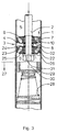
- a hydraulic pressure stop according to the invention is shown in Figs. 3 and 4.
- kolbenstangenend herb under the working piston 4 an inflow piston 21 arranged with different flow channels 22, 23. Both flow channels 22, 23 are in turn covered by spring washers 24, 25 in the interior.
- an end area is 27, here for the hydraulic pressure stop, determined by a compression spring 28, located at the the piston rod 2 facing away from the wall of the damper tube 1 at this is supported.
- a Abdeckglocke 29 attached, which has a recess 30 into which the fastening nut 31 for holding the damper piston 3 on the piston rod 2 dip can.
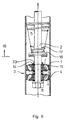
- the effect of the hydraulic pressure stop according to FIG. 7 corresponds to the mode of action of the hydraulic pressure stop according to FIG. 4, as soon as the damper piston 3 enters the corresponding end portion 27. Since the inflow openings of the Throughflow 22 of the inflow piston 21 are closed, flows through the Damping fluid, the flow channels 23, overcoming the through Spring washer 24 caused flow resistance. After distribution in the space 32 is then the working piston 4, overcoming the through Spring washer 7 caused flow resistance flowed through to thereafter to be able to flow through the inflow piston 11 without special flow resistance.
- FIG. 8 The representation of a Buchanschlages invention according to FIG. 8 corresponds to the Representation of FIG. 1.
- an axially yielding spring 33 the - like shown - may be formed as a corrugated spring.
- the distance 34 decreases continuously, until it reduces to zero at the latest, as soon as the compression spring 17 to block drove.
- the reduction of the distance 34 as a function of the compression the compression spring 17 is dependent on the design of the compression spring 17 and the spring 33. The distance 34 can thus already reach zero before the compression spring 17 is moved to block.
Landscapes
- Engineering & Computer Science (AREA)
- General Engineering & Computer Science (AREA)
- Mechanical Engineering (AREA)
- Fluid-Damping Devices (AREA)
- Types And Forms Of Lifts (AREA)
Description
Die Erfindung betrifft eine Vorrichtung zur Erhöhung der Dämpfung am Endbereich von hydraulischen Schwingungsdämpfern mit hydraulischen Mitteln wobei der Durchströmquerschnitt des den Dämpferinnenraum in zwei Arbeitsräume unterteilenden Dämpferkolbens durch teilweises Abdecken der Zuströmfläche reduziert wird und wobei die Zuströmfläche aus mehreren nicht miteinander verbundenen Einzelzuströmflächen besteht. Derartige Vorrichtungen werden auch hydraulischer Zuganschlag bzw. hydraulischer Druckanschlag genannt.The invention relates to a device for increasing the damping at the end of hydraulic vibration dampers with hydraulic means wherein the flow cross-section of the damper interior in two work spaces dividing damper piston is reduced by partially covering the inflow and wherein the inflow surface consists of a plurality of non-interconnected Einzelzuströmflächen. Such devices are also hydraulic Zuganschlag or called hydraulic pressure stop.
Um zu verhindern, daß bei hydraulischen Schwingungsdämpfern der Arbeitskolben ungebremst in seine Endlage fährt, werden Zug- bzw. Druckanschläge vorgesehen. Speziell bei Schwingungsdämpfern an Kraftfahrzeugen hat es sich als vorteilhaft erwiesen, diese Zug- bzw. Druckanschläge mit hydraulischen Mitteln zu gestalten. Üblicherweise wird daher vorgesehen, daß die Zuströmquerschnitte des Arbeitskolbens am Ende des Hubweges mittels Scheiben oder Glocken teilweise abgedeckt werden. Die Abdeckscheiben bzw. Abdeckglocken sind dabei von einer Feder getragen, so daß am Endbereich des Hubweges eine erhöhte Dämpfung auftritt.To prevent that in hydraulic vibration dampers of the working piston unrestrained moves into its final position, train or pressure stops are provided. Especially with vibration dampers on motor vehicles, it has proven to be advantageous to design these train or pressure stops by hydraulic means. Usually Therefore, it is provided that the inflow cross sections of the working piston be partially covered at the end of the stroke by means of discs or bells. The cover or cover bells are supported by a spring, so that at the end of the stroke increased damping occurs.
Derartige hydraulische Zug- bzw. Druckanschläge sind aus der DE-Lit. Reimpell, Stoll, Fahrwerktechnik: Stoß- und Schwingungsdämpfer, Seiten 186 bis 188 bekannt. Nachteilig hierbei erfolgt ein teilweises Abdecken der Einzelzuströmflächen, hier der Bohrungen, so daß sichelförmige Restzuströmöffnungen offenbleiben. Aufgrund von Toleranzen, Verschiebungen und sonstigen Einflüssen, kann nicht sichergestellt werden, daß diese sichelförmigen Restzuströmöffnungen einen gleichen und gleichbleibenden Querschnitt aufweisen. Durch die Sichelform ergibt das eine hohe Ungenauigkeit der Zuströmung und damit der Dämpfung im Arbeitsbereich der hydraulischen Anschläge. Such hydraulic tension or pressure stops are from the DE-Lit. Reimpell, Stoll, chassis technology: shock and vibration damper, pages 186 to 188 known. The disadvantage here is a partial covering the Einzelzuströmflächen, here the Holes, so that sickle-shaped Restzuströmöffnungen remain open. Owing to Tolerances, shifts and other influences can not be guaranteed be that these crescent-shaped Restzuströmöffnungen a same and consistent Have cross-section. The sickle shape results in a high degree of inaccuracy the inflow and thus the damping in the working area of the hydraulic Attacks.
Aus der GB-A-1 547 193 ist eine Vorrichtung mit allen Merkmalen des Oberbegriffs
des Patentanspruchs 1 bekannt. Bei dieser bekannten Vorrichtung erfolgt die
Anschlagbewegung im Endbereich unkontrolliert.From GB-A-1 547 193 there is a device with all the features of the preamble
of
Der Erfindung liegt die Aufgabe zugrunde, die Vorrichtung gemäß Oberbegriff des
Patentanspruchs 1 so weiterzubilden, dass die Anschlagbewegung kontrollierter
gesteuert werden kann.The invention is based on the object, the device according to the preamble of
To further develop
Diese Aufgabe wird erfindungsgemäß mit den Merkmalen des Anspruchs 1 gelöst.
Vorteilhafte Aus- und Weiterbildungen sind in den Ansprüchen 2 bis 6 beschrieben.This object is achieved with the features of
Die mit der Erfindung erzielten Vorteile bestehen insbesondere darin, daß mit einfachen Bauteilen eine sichere und gleichbleibende hydraulische Anschlagdämpfung mit einer kontrolliert gesteuerten Anschlagbewegung erzielt werden kann.The advantages achieved by the invention are in particular that with simple Components provide a safe and consistent hydraulic stop cushioning can be achieved with a controlled controlled stop movement.
Als besonderer Vorteil ist hervorzuheben, daß durch die Möglichkeit des Einsatzes unterschiedlicher Federscheiben bzw. Federscheibenpakete austrittsseitig am Zuströmkolben für die Druck- bzw. Zuganschlagdämpfung erreicht werden kann, daß sich die Druck-/Zuganschlagkennung bezüglich max/min. Dämpfkraft sowie Anstiegsgradient und Anlaufverhalten entsprechend den Erfordernissen beliebig abstimmen läßt und für das Fahrverhalten des Fahrzeugs reproduzierbare Dämpfkräfte erzeugt, was letztendlich zu einem berechenbareren Verhalten führt und der Sicherheit dient.As a special advantage, it should be emphasized that by the possibility of using different spring washers or spring disk packages on the outlet side of the inflow piston for the pressure or Zuganschlagdämpfung can be achieved that the pressure / Zuganschlagkennung in terms of max / min. Damping force and gradient and startup behavior accordingly the requirements and vote for the driving behavior of the Vehicle produces reproducible damping forces, ultimately becoming more predictable Behavior leads and security serves.
Im Folgenden wird die Erfindung anhand einer Zeichnung näher erläutert. In den Fig. 8 und 9 ist die erfindungsgemäße Vorrichtung dargestellt. Es zeigen
- Fig. 1
- einen hydraulischen Zuganschlag außer Funktion,
- Fig. 2
- einen hydraulischen Zuganschlag in Funktion,
- Fig. 3
- einen hydraulischen Druckanschlag außer Funktion,
- Fig. 4
- einen hydraulischen Druckanschlag in Funktion,
- Fig. 5
- einen hydraulischen Zug- und Druckanschlag außer Funktion,
- Fig. 6
- einen hydraulischen Zug- und Druckanschlag bei Funktion des Zuganschlages,
- Fig. 7
- einen hydraulischen Zug- und Druckanschlag bei Funktion des Druckanschlages,
- Fig. 8
- einen erfindungsgemäßen, weich gesteuerten Zuganschlag gemäß Fig. 1 und
- Fig. 9
- einen erfindungsgemäßen, weich gesteuerten Zuganschlag gemäß Fig. 2.
- Fig. 1
- a hydraulic draft stop inoperative,
- Fig. 2
- a hydraulic draft stop in function,
- Fig. 3
- a hydraulic pressure stop function,
- Fig. 4
- a hydraulic pressure stop in function,
- Fig. 5
- a hydraulic pull and pressure stop function,
- Fig. 6
- a hydraulic pull and pressure stop with function of the Zuganschlages,
- Fig. 7
- a hydraulic pull and pressure stop with function of the pressure stop,
- Fig. 8
- a soft-controlled draft stop according to the invention shown in FIG. 1 and
- Fig. 9
- a soft-controlled draft stop according to the invention according to FIG. 2.
Hydraulische Schwingungsdämpfer, speziell für Kraftfahrzeuge, weisen ein Dämpferrohr
1 auf, in das oszillierend eine Kolbenstange 2 eintaucht. Am eintauchenden
Ende der Kolbenstange 2 ist ein Dämpferkolben 3 mit wenigstens einem Arbeitskolben
4 angebracht, der den mit Dämpfungsflüssigkeit gefüllten Innenraum des
Dämpferrohres 1 in zwei Arbeitsräume 5, 6 unterteilt. Federscheiben 7, 8 oder
Federscheibenpakete wirken als Ventile in jeweils eine Arbeitsrichtung des Arbeitskolbens
4 und erzeugen die gewünschte Dämpfungskraft. Diese Federscheiben 7, 8
decken jeweils den Austritt von im Arbeitskolben 4 angeordneten Durchströmkanälen
9, 10 ab. Üblicherweise ist die Anzahl und Form der Durchströmkanäle 9, 10 gleich
und liegen auf einem gemeinsamen Durchmesser. Sie wechseln sich hier ab und
unterscheiden sich dadurch, daß sie in unterschiedlicher Richtung schräg zur Kolbenstangenachse
verlaufen. Dadurch ist es möglich, daß die Federscheiben 7, 8 den
jeweils innenliegenden Ausströmquerschnitt der Durchströmkanäle 9, 10 abdecken,
wobei die jeweils außenliegenden Zuströmquerschnitte offenbleiben. Andere Formen
von Arbeitskolben mit anderen, beispielsweise fingerförmig ausgebildeten Federscheiben,
sind in gleicher Weise einsetzbar.Hydraulic vibration dampers, especially for motor vehicles, have a
In den Fig. 1 und 2 ist ein hydraulischer Zuganschlag gezeigt. Hierzu trägt die Kolbenstange
2 kolbenstangenseitig neben dem Arbeitskolben 4 einen Zuströmkolben
11, der in gleicher Weise aufgebaut ist wie der Arbeitskolben 4. Auch am Zuströmkolben
11 sind beidseitig die innenliegenden Ausströmöffnungen der Durchströmkanäle
12, 13 über Federscheiben 14, 15 abgedeckt. Die dem Arbeitskolben 4 abgewandte
Federscheibe 14 des Zuströmkolbens 11 weist jedoch Durchbrüche 16
auf. Eine kolbenstangenaustrittsseitig angeordnete Druckfeder 17 stützt sich kolbenstangenaußenseitig
am Dämpferrohr 1 ab. Sie trägt an ihrem anderen Ende eine Abdeckplatte
18.In Figs. 1 and 2, a hydraulic Zuganschlag is shown. This is done by the
In Fig. 1 ist die Arbeitsstellung von Kolbenstange 2 und Dämpferkolben 3 gezeigt,
d.h. der Schwingungsdämpfer arbeitet im Normalbetrieb. Fig. 1 zeigt die Durchströmverhältnisse
der Dämpfungsflüssigkeit in Zugrichtung, also bei Ausfahren der Kolbenstange
2 aus dem Dämpferrohr 1. Dabei weist der obere Arbeitsraum 5 gegenüber
dem unteren Arbeitsraum 6 einen Überdruck auf, was zum Durchströmen der
Dämpfungsflüssigkeit durch den Dämpferkolben 3 vom oberen Arbeitsraum 5 in den
unteren Arbeitsraum 6 führt. Solange der Dämpferkolben 3 noch nicht in den von der
Lage der Druckfeder 17 bestimmten Endbereich 19 der hydraulischen Zuganschlagdämpfung
gelangt, kann die Dämpfungsflüssigkeit frei durch den Durchströmkanal 12
des Zuströmkolbens 11 zu den Eintrittsöffnungen des Arbeitskolbens 4 gelangen, da
die obere Federscheibe 14 des Zuströmkolbens 11 die vorbeschriebenen Durchbrüche
16 aufweist. Die Arbeitsdämpfung in Zugrichtung wird durch die Ausbildung der
Federscheibe 8 am Arbeitskolben 4 bestimmt.In Fig. 1 the working position of the
Sobald der Dämpferkolben 3 in den Endbereich 19 für den hydraulischen Zuganschlag
kommt, wie dieses in Fig. 2 dargestellt ist, sich also der Zuströmkolben 11
gegen die Abdeckplatte 18 der Druckfeder 17 legt, wird die Zuströmöffnung des
Durchströmkanals 12 des Zuströmkolbens 11 verschlossen, da die Abdeckplatte 18
die Durchbrüche 16 in der Federscheibe 14 verschließt. Die Dämpfungsflüssigkeit
durchfließt den Dämpferkolben 3 dann durch den sich von außen nach innen erstreckenden
Durchströmkanal 13 des Zuströmkolbens 11, der von der Federscheibe
15 abgedeckt wird. Über den Zwischenraum 20 fließt die Dämpfungsflüssigkeit dann
in die Einströmöffnung des Durchströmkanals 9 des Arbeitskolbens 4. Dadurch, daß
nun sowohl die Federscheibe 15 als auch die Federscheibe 8 einen Strömungswiderstand
bilden, ergibt sich die erhöhte hydraulische Dämpfung im Endbereich 19
und somit die Funktion des hydraulischen Zuganschlags.Once the
Ein hydraulischer Druckanschlag nach der Erfindung ist in den Fig. 3 und 4 dargestellt.
Hier ist kolbenstangenendseitig unter dem Arbeitskolben 4 ein Zuströmkolben
21 mit unterschiedlichen Durchströmkanälen 22, 23 angeordnet. Beide Durchströmkanäle
22, 23 sind wiederum durch Federscheiben 24, 25 im Innenbereich abgedeckt.
Bei der Ausbildung des Druckanschlages weist die kolbenstangenendseitige
Federscheibe 25 Durchbrüche 26 auf. Wiederum ist ein Endbereich 27, hier für den
hydraulischen Druckanschlag, durch eine Druckfeder 28 bestimmt, die sich am von
der Kolbenstange 2 abgewandten Ende gegen die Wandung des Dämpferrohrs 1 an
diesem abstützt. Am gegenüberliegenden Ende der Druckfeder ist eine Abdeckglocke
29 angebracht, die eine Ausnehmung 30 aufweist, in die die Befestigungsmutter
31 zum Halten des Dämpferkolbens 3 auf der Kolbenstange 2 eintauchen
kann.A hydraulic pressure stop according to the invention is shown in Figs. 3 and 4.
Here is kolbenstangenendseitig under the working
Während der normalen Arbeitsfunktion des Schwingungsdämpfers, wie sie beim
Einfahren der Kolbenstange 2 in das Dämpferrohr 1 in Fig. 3 dargestellt ist, entwikkelt
sich im unteren Arbeitsraum 6 ein gegenüber dem Druck im Arbeitsraum 5 erhöhter
Druck. Das führt zum Durchfließen der Dämpfungsflüssigkeit durch den
Arbeitskolben 4 vom unteren Arbeitsraum 6 in den oberen Arbeitsraum 5. Die
Dämpfungsflüssigkeit kann aufgrund der Durchbrüche 26 in der Federscheibe 25 die
Durchströmkanäle 22 im Zuströmkolben 21 frei durchfließen und durchströmt dann
den Durchströmkanal 10 des Arbeitskolbens 4, der von der Federscheibe 7 federnd
nachgiebig abgedeckt ist. Sobald der Dämpferkolben 3 entsprechend Fig. 4 in den
druckseitigen Endbereich 27 kommt, sich also die Abdeckglocke 29 gegen die inneren
Einströmöffnungen des Zuströmkolbens 21 legt, ist der Durchströmkanal 22 verschlossen.
Die Dämpfungsflüssigkeit muß dann durch den Durchströmkanal 23 fließen,
der durch die federnd nachgiebige Federscheibe 24 verschlossen wird. Über
den Zwischenraum 32 wird die Dämpfungsflüssigkeit danach zur Einströmöffnung
des Durchströmkanals 10 des Arbeitskolbens 4 geführt, welcher wiederum durch die
federnd nachgiebige Federscheibe 7 abgedeckt ist. Durch die Addition der durch die
Federscheiben 7 und 24 erzeugten Strömungswiderstände ergibt sich die gewünschte
erhöhte hydraulische Dämpfung für den hydraulischen Druckanschlag.During the normal working function of the vibration damper, as with the
Retraction of the
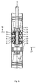
In den Fig. 5 bis 7 ist die Ausbildung eines hydraulischen Schwingungsdämpfers mit
einem hydraulischen Druckanschlag und einem hydraulischen Zuganschlag dargestellt.
Diese Ausbildung stellt also die Kombination der Ausbildungen entsprechend
den Fig. 1 bis 4 dar. Der zugstangenendseitige Dämpferkolben 3 besteht hier aus
dem mittig angeordneten Arbeitskolben 4, dem sich axial beidseitig die Zuströmkolben
11 und 21 anschließen. Ebenso sind in den Endbereichen 19, 27 Druckfedern
17, 28 fixiert, die eine Abdeckplatte 18 bzw. eine Abdeckglocke 29 tragen. In Figs. 5 to 7, the formation of a hydraulic vibration damper with
a hydraulic pressure stop and a hydraulic Zuganschlag shown.
This training thus provides the combination of training accordingly
1 to 4. The
Während der normalen Dämpfungsfunktion, also in Zug- und Druckrichtung der Kolbenstange
2 und damit des Dämpfungskolbens 3 entsprechend Fig. 5, kann die
Dämpfungsflüssigkeit ungehindert die Durchströmkanäle 12 durch den Zuströmkolben
11 bzw. die Durchströmkanäle 22 durch den Zuströmkolben 21 durchdringen, da die
Durchbrüche 16, 26 durch die Federscheiben 14, 25 offen sind. Lediglich die
Federscheiben 7, 8 des Arbeitskolbens 4 bestimmen die jeweilige Dämpfung des ein-
oder ausfahrenden Dämpferkolbens 3.During the normal damping function, ie in the direction of tension and compression of the
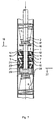
Beim Einfahren des Dämpferkolbens 3 in den Endbereich 19 für die hydraulische
Zuganschlagdämpfung gemäß Fig. 6 werden die Einströmöffnungen der Durchströmkanäle
12 des Zuströmkolbens 11 verschlossen, wie dieses bereits zu Fig. 2
beschrieben ist. Die Dämpfungsflüssigkeit durchströmt dann mit erhöhtem Widerstand
den durch die Federscheibe 15 abgedeckten Durchströmkanal 13 des Zuströmkolbens
11. Wie Fig. 6 zu entnehmen ist, kann die nach Dämpfung durch die Federscheibe 8
aus dem Arbeitskolben 4 austretende Dämpfungsflüssigkeit ungehindert den
Zuströmkolben 21 durchströmen, da die Durchbrüche 26 in der Federscheibe 25 ein
ungehindertes Durchströmen durch die Durchströmkanäle 22 erlauben.When retracting the
Die Wirkung des hydraulischen Druckanschlages gemäß Fig. 7 entspricht der Wirkungsweise
des hydraulischen Druckanschlages gemäß Fig. 4, sobald der Dämpferkolben
3 in den entsprechenden Endbereich 27 einfährt. Da die Zuströmöffnungen der
Durchströmkanäle 22 des Zuströmkolbens 21 verschlossen sind, durchströmt die
Dämpfungsflüssigkeit die Durchströmkanäle 23 unter Überwindung des durch die
Federscheibe 24 hervorgerufenen Strömungswiderstandes. Nach Verteilung im Zwischenraum
32 wird dann der Arbeitskolben 4 unter Überwindung des durch die
Federscheibe 7 hervorgerufenen Strömungswiderstandes durchflossen, um danach
ohne besonderen Strömungswiderstand den Zuströmkolben 11 durchfließen zu können.The effect of the hydraulic pressure stop according to FIG. 7 corresponds to the mode of action
of the hydraulic pressure stop according to FIG. 4, as soon as the
Die Darstellung eines erfindungsgemäßen Zuganschlages gemäß Fig. 8 entspricht der
Darstellung gemäß Fig. 1. Bei dieser Ausbildung liegt zwischen der Abdeckplatte 18
und dem Zuströmkolben
11 oberhalb der Federscheibe 14 eine axial nachgebende Feder 33, die - wie
dargestellt - als Wellfeder ausgebildet sein kann.The representation of a Zuganschlages invention according to FIG. 8 corresponds to the
Representation of FIG. 1. In this embodiment lies between the cover plate 18th
and the
Sobald der Dämpferkolben 3, wie in Fig. 9 gezeigt, entsprechend Fig. 2 in den Endbereich
19 für den hydraulischen Zuganschlag kommt, legt sich die am unteren Ende
der Druckfeder 17 angeordnete Abdeckplatte 18 gegen die Feder 33. Zwischen der
Abdeckplatte 18 und der auf dem Zuströmkolben 11 liegenden Federscheibe 14 verbleibt
ein Abstand 34, durch den eine gedrosselte Zuströmung der Dämpfungsflüssigkeit
aus dem Arbeitsraum 5 in den Durchströmkanal 12 möglich bleibt.Once the
Je stärker der Dämpferkolben 3 gegen die Druckfeder 17 gezogen wird, desto stärker
ist auch die durch diese Druckfeder 17 aufgebrachte Andrückkraft auf die Abdeckplatte
18 und damit auf die Feder 33. Somit verringert sich der Abstand 34 kontinuierlich,
bis er sich spätestens auf Null reduziert, sobald die Druckfeder 17 auf Block
gefahren ist. Die Verringerung des Abstandes 34 in Abhängigkeit vom Zusammendrücken
der Druckfeder 17 ist abhängig von der Auslegung der Druckfeder 17 und
der Feder 33. Der Abstand 34 kann demgemäß auch bereits Null erreichen, bevor
die Druckfeder 17 auf Block zusammengefahren ist. The stronger the
- 1.1.
- Dämpferrohrdamper tube
- 2.Second
- Kolbenstangepiston rod
- 3.Third
- Dämpferkolbendamper piston
- 4.4th
- Arbeitskolbenworking piston
- 5.5th
- Arbeitsraumworking space
- 6.6th
- Arbeitsraumworking space
- 7.7th
- Federscheibespring washer
- 8.8th.
- Federscheibespring washer
- 9.9th
- Durchströmkanalflow-through
- 10.10th
- Durchströmkanalflow-through
- 11.11th
- ZuströmkolbenZuströmkolben
- 12.12th
- Durchströmkanalflow-through
- 13.13th
- Durchströmkanalflow-through
- 14.14th
- Federscheibespring washer
- 15.15th
- Federscheibespring washer
- 16.16th
- Durchbruchbreakthrough
- 17.17th
- Druckfedercompression spring
- 18.18th
- Abdeckplattecover
- 19.19th
- Endbereichend
- 20.20th
- Zwischenraumgap
- 21.21st
- ZuströmkolbenZuströmkolben
- 22.22nd
- Durchströmkanalflow-through
- 23.23rd
- Durchströmkanalflow-through
- 24.24th
- Federscheibespring washer
- 25.25th
- Federscheibespring washer
- 26.26th
- Durchbruchbreakthrough
- 27.27th
- Endbereichend
- 28.28th
- Druckfedercompression spring
- 29.29th
- Abdeckglocke Abdeckglocke
- 30.30th
- Ausnehmungrecess
- 31.31st
- Befestigungsmutterfixing nut
- 32.32nd
- Zwischenraumgap
- 33.33rd
- Federfeather
- 34.34th
- Abstanddistance
Claims (6)
- Device for increasing the damping effect at the end region (19, 27) of hydraulic vibration dampers with hydraulic media, wherein the through-flow cross-section of the damper piston (3) which divides the inner damper chamber into two working chambers is reduced by partial covering of the in-flow area, wherein the in-flow area consists of a plurality of individual in-flow areas which are not connected to each other, wherein one or a plurality of the individual in-flow areas are completely covered and wherein sealing is achieved by a cover plate (18), which is disposed at the end of a spring (17, 28), or by a correspondingly held cover bell (29), characterised in that an axially yielding spring (33) is disposed between the cover plate (18) or cover bell (29) and in-flow piston (11, 21).
- Device as claimed in claim 1, characterised in that the individual in-flow areas are disposed on at least two annular regions of the damper piston (3) which lie one inside the other but do not touch.
- Device as claimed in claim 2, characterised in that the annular regions are separated from each other by circular edges or cuts.
- Device as claimed in any one or several of claims 1 to 3, characterised in that the damper piston (3) has one or a plurality of in-flow pistons (11, 21) in addition to a working piston (4).
- Device as claimed in claim 4, characterised in that the in-flow piston(s) (11, 21) has individual in-flow areas.
- Device as claimed in claim 4 or 5, characterised in that the non-closable through-flow channels (13, 23) of the in-flow piston(s) (11, 21) are covered on the outlet side by spring plates (15, 24).
Applications Claiming Priority (2)
| Application Number | Priority Date | Filing Date | Title |
|---|---|---|---|
| DE19945632A DE19945632B4 (en) | 1999-09-23 | 1999-09-23 | Device for increasing the damping |
| DE19945632 | 1999-09-23 |
Publications (2)
| Publication Number | Publication Date |
|---|---|
| EP1087153A1 EP1087153A1 (en) | 2001-03-28 |
| EP1087153B1 true EP1087153B1 (en) | 2005-04-27 |
Family
ID=7923055
Family Applications (1)
| Application Number | Title | Priority Date | Filing Date |
|---|---|---|---|
| EP00118064A Expired - Lifetime EP1087153B1 (en) | 1999-09-23 | 2000-08-23 | Device for increasing damping |
Country Status (5)
| Country | Link |
|---|---|
| US (1) | US6681906B1 (en) |
| EP (1) | EP1087153B1 (en) |
| BR (1) | BR0004339A (en) |
| DE (2) | DE19945632B4 (en) |
| ES (1) | ES2237369T3 (en) |
Families Citing this family (13)
| Publication number | Priority date | Publication date | Assignee | Title |
|---|---|---|---|---|
| DE10222940C1 (en) * | 2002-05-24 | 2003-07-31 | Zf Sachs Ag | Vibration damper with hydraulic pressure stop has piston rod movement acting on second piston via transmission spring |
| DE102004035613A1 (en) * | 2004-07-22 | 2006-03-16 | Stabilus Gmbh | Gas spring with end cushioning |
| JP4753238B2 (en) * | 2005-09-09 | 2011-08-24 | ヤマハ発動機株式会社 | Hydraulic shock absorber |
| US8162112B2 (en) | 2007-02-09 | 2012-04-24 | Competition Tire East | Methods and apparatus for protecting a shock absorber from bottoming |
| CA2639822A1 (en) * | 2007-09-26 | 2009-03-26 | Bombardier Recreational Products Inc. | Position sensitive shock absorber |
| US8297418B2 (en) * | 2008-06-05 | 2012-10-30 | Tenneco Automotive Operating Company Inc. | Nested check high speed valve |
| DE102009012515B4 (en) | 2009-03-10 | 2018-11-22 | Man Truck & Bus Ag | vibration |
| JP5936128B2 (en) | 2012-12-26 | 2016-06-15 | Kyb株式会社 | Shock absorber |
| US9091320B1 (en) * | 2014-01-08 | 2015-07-28 | Thyssenkrupp Bilstein Of America, Inc. | Multi-stage shock absorber |
| JP6359761B2 (en) * | 2014-10-01 | 2018-07-18 | ベイジンウェスト・インダストリーズ・カンパニー・リミテッドBeijingwest Industries Co., Ltd. | Damper assembly |
| FR3049222B1 (en) * | 2016-03-25 | 2018-04-13 | Peugeot Citroen Automobiles Sa | HYDRAULIC SUSPENSION SYSTEM OF A VEHICLE |
| FR3049502B1 (en) * | 2016-03-31 | 2018-04-20 | Peugeot Citroen Automobiles Sa | VEHICLE WITH HYDRAULIC SUSPENSION SYSTEM |
| DE102019213913A1 (en) * | 2019-09-12 | 2021-03-18 | Thyssenkrupp Ag | Hydraulic vibration damper with one pull and one pressure stop |
Family Cites Families (17)
| Publication number | Priority date | Publication date | Assignee | Title |
|---|---|---|---|---|
| US1445615A (en) * | 1920-11-24 | 1923-02-13 | Jeffrey T Ferres | Shock absorber |
| US2355491A (en) * | 1943-03-22 | 1944-08-08 | Monroe Auto Equipment Co | Hydraulic shock absorber |
| US2456736A (en) * | 1945-01-25 | 1948-12-21 | Gen Motors Corp | Shock absorber |
| US2599477A (en) * | 1950-03-17 | 1952-06-03 | Gabriel Co | Shock absorber |
| GB763557A (en) * | 1954-11-16 | 1956-12-12 | Newtcn & Bennett Ltd | Improvements in or relating to hydraulic shock absorbers |
| US3111201A (en) * | 1961-04-27 | 1963-11-19 | Ford Motor Co | Hydraulic shock absorber |
| DE1249037B (en) * | 1961-06-02 | 1967-08-31 | ||
| DE1430494B1 (en) * | 1962-01-22 | 1970-04-02 | Carbon Christian Marie Lucien | Hydropneumatic single tube shock absorber for motor vehicles |
| DE1505360A1 (en) * | 1965-02-06 | 1970-03-26 | Bourcier De Carbon Christian M | Hydropneumatic single tube shock absorber for motor vehicles |
| US4004662A (en) * | 1973-10-16 | 1977-01-25 | Volkswagenwerk Aktiengesellschaft | Shock absorber with different damping effects at different parts of stroke |
| GB1547193A (en) * | 1977-08-15 | 1979-06-06 | Girling Ltd | Telescopic suspension units for vehicles |
| FR2421309A1 (en) * | 1978-03-29 | 1979-10-26 | Bourcier Carbon Christian | IMPROVEMENTS TO MONOTUBE SHOCK ABSORBERS |
| DE3500101C1 (en) * | 1985-01-03 | 1986-07-24 | Ford-Werke AG, 5000 Köln | Hydraulic two-tube vibration damper |
| DE3533387A1 (en) * | 1985-09-19 | 1987-03-26 | Fichtel & Sachs Ag | TWO-TUBE VIBRATION DAMPER WITH HYDRAULIC PRESSURE STOP |
| DE3623787A1 (en) * | 1986-07-15 | 1988-01-21 | Bauer Fritz & Soehne Ohg | GAS SPRING WITH LIMIT DAMPING |
| US5219414A (en) * | 1989-04-24 | 1993-06-15 | Atsugi Unisia Corporation | Variable damping force shock absorber with stroke dependent variation characteristics of damping force |
| US6102170A (en) * | 1998-05-07 | 2000-08-15 | Tenneco Automotive Inc. | Passive anti-roll system |
-
1999
- 1999-09-23 DE DE19945632A patent/DE19945632B4/en not_active Expired - Lifetime
-
2000
- 2000-07-11 US US09/613,779 patent/US6681906B1/en not_active Expired - Lifetime
- 2000-08-23 DE DE50010148T patent/DE50010148D1/en not_active Expired - Lifetime
- 2000-08-23 EP EP00118064A patent/EP1087153B1/en not_active Expired - Lifetime
- 2000-08-23 ES ES00118064T patent/ES2237369T3/en not_active Expired - Lifetime
- 2000-09-20 BR BR0004339-7A patent/BR0004339A/en not_active IP Right Cessation
Also Published As
| Publication number | Publication date |
|---|---|
| DE19945632A1 (en) | 2001-04-26 |
| ES2237369T3 (en) | 2005-08-01 |
| US6681906B1 (en) | 2004-01-27 |
| EP1087153A1 (en) | 2001-03-28 |
| DE50010148D1 (en) | 2005-06-02 |
| DE19945632B4 (en) | 2005-11-03 |
| BR0004339A (en) | 2001-04-03 |
Similar Documents
| Publication | Publication Date | Title |
|---|---|---|
| EP1152166B2 (en) | Shock absorber with amplitude-dependent damping | |
| EP1767810B1 (en) | Throttle valve device with progressive damping force characteristics | |
| DE19749356B4 (en) | Two-stage shock absorber with stroke-dependent damping | |
| EP0715091B1 (en) | Adjustable vibration damper | |
| EP0926384B1 (en) | Piston for a hydraulic vibration damper | |
| DE2229945C2 (en) | Impact absorbers for motor vehicle bumpers | |
| EP1775495A2 (en) | Vibration damper with adjustable damping force | |
| EP1087153B1 (en) | Device for increasing damping | |
| DE102005008162B3 (en) | Damping valve arrangement for vibration damper, has valve washer twisted on two valve seat surfaces and resting on surfaces with good sealing function, where one surface implements lift-off movement with another valve washer | |
| EP1788276A2 (en) | Shock absorber with a damping force depending on the amplitude | |
| DE202009004752U1 (en) | Damper for furniture | |
| DE2833776C2 (en) | Two-chamber engine mount | |
| DE2825524C2 (en) | ||
| DE2218952A1 (en) | HYDRAULIC IMPACT ABSORBER | |
| DE19738617C2 (en) | Shock absorbers for motor vehicles | |
| DE19542293B4 (en) | Vibration damper with adjustable damping force | |
| DE3246866C2 (en) | ||
| EP1281888B1 (en) | Hydraulic shock absorber | |
| DE2344693C2 (en) | Working pistons for hydraulic impact dampers, in particular for motor vehicles | |
| DE19849429C2 (en) | High-performance vibration dampers | |
| DE3010690A1 (en) | Hydraulic suspension damper for vehicle - has axial grooves in stop ring steps working with additional slotted damping rings | |
| DE102019212964A1 (en) | Vibration damper with additional damping | |
| EP1182374B1 (en) | Controllable shock absorber for vehicles and method for adjusting this shock absorber | |
| DE102005048942B4 (en) | Piston-cylinder unit | |
| DE102013008889B4 (en) | Vibration damper for a vehicle |
Legal Events
| Date | Code | Title | Description |
|---|---|---|---|
| PUAI | Public reference made under article 153(3) epc to a published international application that has entered the european phase |
Free format text: ORIGINAL CODE: 0009012 |
|
| 17P | Request for examination filed |
Effective date: 20010117 |
|
| AK | Designated contracting states |
Kind code of ref document: A1 Designated state(s): DE ES FR GB IT |
|
| AX | Request for extension of the european patent |
Free format text: AL;LT;LV;MK;RO;SI |
|
| AKX | Designation fees paid |
Free format text: DE ES FR GB IT |
|
| RAP1 | Party data changed (applicant data changed or rights of an application transferred) |
Owner name: THYSSENKRUPP BILSTEIN GMBH |
|
| 17Q | First examination report despatched |
Effective date: 20030516 |
|
| GRAP | Despatch of communication of intention to grant a patent |
Free format text: ORIGINAL CODE: EPIDOSNIGR1 |
|
| GRAS | Grant fee paid |
Free format text: ORIGINAL CODE: EPIDOSNIGR3 |
|
| GRAA | (expected) grant |
Free format text: ORIGINAL CODE: 0009210 |
|
| AK | Designated contracting states |
Kind code of ref document: B1 Designated state(s): DE ES FR GB IT |
|
| REG | Reference to a national code |
Ref country code: GB Ref legal event code: FG4D Free format text: NOT ENGLISH |
|
| GBT | Gb: translation of ep patent filed (gb section 77(6)(a)/1977) |
Effective date: 20050427 |
|
| REF | Corresponds to: |
Ref document number: 50010148 Country of ref document: DE Date of ref document: 20050602 Kind code of ref document: P |
|
| REG | Reference to a national code |
Ref country code: ES Ref legal event code: FG2A Ref document number: 2237369 Country of ref document: ES Kind code of ref document: T3 |
|
| ET | Fr: translation filed | ||
| PLBE | No opposition filed within time limit |
Free format text: ORIGINAL CODE: 0009261 |
|
| STAA | Information on the status of an ep patent application or granted ep patent |
Free format text: STATUS: NO OPPOSITION FILED WITHIN TIME LIMIT |
|
| 26N | No opposition filed |
Effective date: 20060130 |
|
| REG | Reference to a national code |
Ref country code: FR Ref legal event code: PLFP Year of fee payment: 17 |
|
| REG | Reference to a national code |
Ref country code: FR Ref legal event code: PLFP Year of fee payment: 18 |
|
| REG | Reference to a national code |
Ref country code: FR Ref legal event code: PLFP Year of fee payment: 19 |
|
| PGFP | Annual fee paid to national office [announced via postgrant information from national office to epo] |
Ref country code: FR Payment date: 20180827 Year of fee payment: 19 Ref country code: ES Payment date: 20180921 Year of fee payment: 19 |
|
| PGFP | Annual fee paid to national office [announced via postgrant information from national office to epo] |
Ref country code: GB Payment date: 20180822 Year of fee payment: 19 |
|
| PGFP | Annual fee paid to national office [announced via postgrant information from national office to epo] |
Ref country code: DE Payment date: 20190822 Year of fee payment: 20 |
|
| GBPC | Gb: european patent ceased through non-payment of renewal fee |
Effective date: 20190823 |
|
| PG25 | Lapsed in a contracting state [announced via postgrant information from national office to epo] |
Ref country code: FR Free format text: LAPSE BECAUSE OF NON-PAYMENT OF DUE FEES Effective date: 20190831 |
|
| REG | Reference to a national code |
Ref country code: DE Ref legal event code: R071 Ref document number: 50010148 Country of ref document: DE |
|
| PG25 | Lapsed in a contracting state [announced via postgrant information from national office to epo] |
Ref country code: GB Free format text: LAPSE BECAUSE OF NON-PAYMENT OF DUE FEES Effective date: 20190823 Ref country code: IT Free format text: LAPSE BECAUSE OF NON-PAYMENT OF DUE FEES Effective date: 20190823 |
|
| REG | Reference to a national code |
Ref country code: ES Ref legal event code: FD2A Effective date: 20210107 |
|
| PG25 | Lapsed in a contracting state [announced via postgrant information from national office to epo] |
Ref country code: ES Free format text: LAPSE BECAUSE OF NON-PAYMENT OF DUE FEES Effective date: 20190824 |