EP1085286A1 - Echangeur thermique du type a plaques - Google Patents
Echangeur thermique du type a plaques Download PDFInfo
- Publication number
- EP1085286A1 EP1085286A1 EP00911295A EP00911295A EP1085286A1 EP 1085286 A1 EP1085286 A1 EP 1085286A1 EP 00911295 A EP00911295 A EP 00911295A EP 00911295 A EP00911295 A EP 00911295A EP 1085286 A1 EP1085286 A1 EP 1085286A1
- Authority
- EP
- European Patent Office
- Prior art keywords
- heat exchange
- exchange elements
- heat exchanger
- plates
- fluid
- Prior art date
- Legal status (The legal status is an assumption and is not a legal conclusion. Google has not performed a legal analysis and makes no representation as to the accuracy of the status listed.)
- Withdrawn
Links
Images


Classifications
-
- F—MECHANICAL ENGINEERING; LIGHTING; HEATING; WEAPONS; BLASTING
- F28—HEAT EXCHANGE IN GENERAL
- F28F—DETAILS OF HEAT-EXCHANGE AND HEAT-TRANSFER APPARATUS, OF GENERAL APPLICATION
- F28F3/00—Plate-like or laminated elements; Assemblies of plate-like or laminated elements
- F28F3/02—Elements or assemblies thereof with means for increasing heat-transfer area, e.g. with fins, with recesses, with corrugations
- F28F3/04—Elements or assemblies thereof with means for increasing heat-transfer area, e.g. with fins, with recesses, with corrugations the means being integral with the element
- F28F3/042—Elements or assemblies thereof with means for increasing heat-transfer area, e.g. with fins, with recesses, with corrugations the means being integral with the element in the form of local deformations of the element
- F28F3/046—Elements or assemblies thereof with means for increasing heat-transfer area, e.g. with fins, with recesses, with corrugations the means being integral with the element in the form of local deformations of the element the deformations being linear, e.g. corrugations
-
- F—MECHANICAL ENGINEERING; LIGHTING; HEATING; WEAPONS; BLASTING
- F28—HEAT EXCHANGE IN GENERAL
- F28D—HEAT-EXCHANGE APPARATUS, NOT PROVIDED FOR IN ANOTHER SUBCLASS, IN WHICH THE HEAT-EXCHANGE MEDIA DO NOT COME INTO DIRECT CONTACT
- F28D9/00—Heat-exchange apparatus having stationary plate-like or laminated conduit assemblies for both heat-exchange media, the media being in contact with different sides of a conduit wall
- F28D9/0031—Heat-exchange apparatus having stationary plate-like or laminated conduit assemblies for both heat-exchange media, the media being in contact with different sides of a conduit wall the conduits for one heat-exchange medium being formed by paired plates touching each other
- F28D9/0043—Heat-exchange apparatus having stationary plate-like or laminated conduit assemblies for both heat-exchange media, the media being in contact with different sides of a conduit wall the conduits for one heat-exchange medium being formed by paired plates touching each other the plates having openings therein for circulation of at least one heat-exchange medium from one conduit to another
-
- F—MECHANICAL ENGINEERING; LIGHTING; HEATING; WEAPONS; BLASTING
- F28—HEAT EXCHANGE IN GENERAL
- F28D—HEAT-EXCHANGE APPARATUS, NOT PROVIDED FOR IN ANOTHER SUBCLASS, IN WHICH THE HEAT-EXCHANGE MEDIA DO NOT COME INTO DIRECT CONTACT
- F28D9/00—Heat-exchange apparatus having stationary plate-like or laminated conduit assemblies for both heat-exchange media, the media being in contact with different sides of a conduit wall
- F28D9/0093—Multi-circuit heat-exchangers, e.g. integrating different heat exchange sections in the same unit or heat-exchangers for more than two fluids
-
- F—MECHANICAL ENGINEERING; LIGHTING; HEATING; WEAPONS; BLASTING
- F25—REFRIGERATION OR COOLING; COMBINED HEATING AND REFRIGERATION SYSTEMS; HEAT PUMP SYSTEMS; MANUFACTURE OR STORAGE OF ICE; LIQUEFACTION SOLIDIFICATION OF GASES
- F25B—REFRIGERATION MACHINES, PLANTS OR SYSTEMS; COMBINED HEATING AND REFRIGERATION SYSTEMS; HEAT PUMP SYSTEMS
- F25B37/00—Absorbers; Adsorbers
-
- F—MECHANICAL ENGINEERING; LIGHTING; HEATING; WEAPONS; BLASTING
- F25—REFRIGERATION OR COOLING; COMBINED HEATING AND REFRIGERATION SYSTEMS; HEAT PUMP SYSTEMS; MANUFACTURE OR STORAGE OF ICE; LIQUEFACTION SOLIDIFICATION OF GASES
- F25B—REFRIGERATION MACHINES, PLANTS OR SYSTEMS; COMBINED HEATING AND REFRIGERATION SYSTEMS; HEAT PUMP SYSTEMS
- F25B39/00—Evaporators; Condensers
- F25B39/02—Evaporators
- F25B39/026—Evaporators specially adapted for sorption type systems
-
- F—MECHANICAL ENGINEERING; LIGHTING; HEATING; WEAPONS; BLASTING
- F25—REFRIGERATION OR COOLING; COMBINED HEATING AND REFRIGERATION SYSTEMS; HEAT PUMP SYSTEMS; MANUFACTURE OR STORAGE OF ICE; LIQUEFACTION SOLIDIFICATION OF GASES
- F25B—REFRIGERATION MACHINES, PLANTS OR SYSTEMS; COMBINED HEATING AND REFRIGERATION SYSTEMS; HEAT PUMP SYSTEMS
- F25B39/00—Evaporators; Condensers
- F25B39/04—Condensers
-
- F—MECHANICAL ENGINEERING; LIGHTING; HEATING; WEAPONS; BLASTING
- F28—HEAT EXCHANGE IN GENERAL
- F28F—DETAILS OF HEAT-EXCHANGE AND HEAT-TRANSFER APPARATUS, OF GENERAL APPLICATION
- F28F2250/00—Arrangements for modifying the flow of the heat exchange media, e.g. flow guiding means; Particular flow patterns
- F28F2250/10—Particular pattern of flow of the heat exchange media
- F28F2250/104—Particular pattern of flow of the heat exchange media with parallel flow
Definitions
- the present invention relates to a plate heat exchanger, and more particularly to a plate heat exchanger for exchanging heat between two fluids flowing alternately through adjacent fluid passages between piled plates, which is suitable for such cases where at least one of the fluids is a low-pressure vapor, or is evaporated with phase change, or is condensed from a vapor, as an evaporator, a low-temperature generator, or a condenser in a refrigerating machine using a low-pressure refrigerant.
- FIGS. 10A and 10B are schematic views showing a conventional plate heat exchanger, FIG. 10A is a front view, and FIG. 10B is a side view.
- FIG. 11 is an exploded explanatory view of FIGS. 10A and 10B.
- FIGS. 10A, 10B and 11 two plates 3 having opening portions 5 at both ends thereof are piled on each other to form a space therebetween, and the peripheral portions of the plates 3 are sealed to form a heat exchange element 2.
- the heat exchange elements 2 are piled on and combined with each other in such a state that the opening portions 5 of the plates 3 communicate with each other, thereby producing a heat exchange structure.
- This heat exchange structure is housed in a shell 20, and fluids flow through the interior and the exterior of the heat exchange elements 2 so as to exchange heat with each other.
- Such a conventional plate heat exchanger requires not only heat exchange elements composed of plates, but also a shell. Thus, such a conventional plate heat exchanger has been problematic in that manufacturing procedure is complicated and various types of components are required.
- FIG. 12 shows an example of an absorber and an evaporator utilizing conventional plate heat exchangers.
- an evaporator 21 and an absorber 22 are disposed on the left side and the right side, respectively.
- Plate heat exchangers for the evaporator and the absorber have been manufactured separately, and the absorber and the evaporator are different from each other in shape.
- Many types of components are used for the absorber and the evaporator, and many man-hours are needed to manufacture the absorber and the evaporator.
- the present invention has been made in view of the above drawbacks. It is therefore an object of the present invention to provide a plate heat exchanger which can easily be manufactured and assembled with a small number of components, can achieve a cost reduction and compactness, and has a high heat exchanging performance.
- a plate heat exchanger characterized in that: two plates, each having a projection and a depression and provided with opening portions at both ends in a longitudinal direction thereof, are piled as a set on each other at peripheries thereof to form a heat exchange element; a plurality of the heat exchange elements are piled so that the opening portions are aligned with each other; a space between the two plates forming the heat exchange element defines a passage for a first fluid; a space between the heat exchange elements adjacent to each other defines a passage for another fluid (a second fluid) having heat exchange relationship with the first fluid; the plate serves as a heat transfer surface for both of the fluids; and the peripheral portions of the heat exchange elements are brought into contact with each other to form a sealed passage for the second fluid when the heat exchange elements are piled on each other.
- an inlet and an outlet for the second fluid may be provided on a surface of the plate at positions other than the opening portions at the both ends constituting an inlet and an outlet for the first fluid.
- Two plate heat exchangers described above may be arranged in parallel in a direction of piling of the heat exchange elements, and the passages for the second fluid in the two plate heat exchangers communicate with each other so that a vapor is generated from one of the plate heat exchangers, and condensed or absorbed by the other of the plate heat exchangers.
- passages curved by projections and depressions are formed inside and outside of heat exchange elements composed of one or two types of components, and the external passages can be formed at a time without use of a shell.
- a complicated plate heat exchanger for exchanging heat between two fluids having different temperatures can be manufactured at low cost from a small number of components by a simple manufacturing process.
- a plate heat exchanger characterized in that: a plurality of heat exchange elements are provided, each of the heat exchange elements being composed of two plates opposed to each other as a set, sealed spaces being provided as two systems inside of the two plates, each of the heat exchange elements having two opening portions as an inlet and an outlet for each of the systems; and different fluids flow through internal spaces in the two systems and through passages outside of the internal spaces, respectively.
- the plurality of the heat exchange elements may be constructed such that the heat exchange elements adjacent to each other communicate with each other, and have peripheral portions which are brought into contact with each other and sealed therebetween.
- the internal spaces in the two systems may be arranged on a right side and a left side, and portions of communication between the plurality of the heat exchange elements are divided into a plurality of segments in a vertical direction.
- a plate heat exchanger characterized in that: a plurality of heat exchange elements are provided, each of the heat exchange elements being composed of two plates opposed to each other as a set, sealed spaces being provided as four systems inside of the two plates, each of the heat exchange elements having two opening portions as an inlet and an outlet for each of the systems; among the four systems, a set of a first system and a second system and a set of a third system and a fourth system are arranged on a right side and a left side, respectively; and different fluids flow through internal spaces in the four systems and through passages outside of the internal spaces, respectively.
- the plurality of the heat exchange elements may be constructed such that the heat exchange elements, adjacent to each other, outside of the set of the first system and the second system and the set of the third system and the fourth system arranged on a right side and a left side communicate with each other, and the peripheral portions of the heat exchange elements adjacent to each other may be brought into contact with each other and sealed therebetween.
- a single plate heat exchanger can perform two or four types of heat exchange.
- a fluid flows as a liquid film on an outer surface of the first system, and is heated by the internal fluid, thereby generating a vapor from the liquid film.
- the second system is utilized for an absorber, the vapor is cooled by the internal fluid, and can hence be condensed on the outer surface of the second system.
- an absorption solution flows as a liquid film on the outer surface, whereby the vapor can be absorbed.
- a plate heat exchanger according to a first embodiment of the present invention will be described below in detail.
- a plate having a shape suitable for meeting the following conditions can be used: Two plates having projections and depressions are piled on each other to form a space therebetween. When the peripheral portions of the two plates are simply piled, the plates are brought into light contact (i.e., line contact) with each other along the whole peripheries. When a force in a direction of piling is increased, the contacting portions are changed in shape to be brought into surface contact with each other. When the force is increased until the projections and depressions of the respective plates are brought into contact with each other, the area of the contact surface is increased, and hence the peripheries of the plates can be sealed by brazing.
- the present invention can be applied to not only a case of brazing, but also a case where a gasket is interposed between the plates and a force is applied from the outside, and a case where the plates are sealed by welding.
- the projections and depressions of the plate according to the present invention can be formed as a corrugated pattern extending in a predetermined direction, and hence a complicated passage curved two-dimensionally can be formed with a relatively simple arrangement.
- a plate heat exchanger is constructed from the above heat exchange elements as follows: A required number of the heat exchange elements are piled in such a manner that the opening portions at both ends and the element peripheral sealing portions which are to form a passage for a second fluid by sealing adjacent heat exchange elements are aligned with each other. The brazing filler material is laid on surfaces on which the opening portions of the heat exchange elements and the element peripheral sealing portions are piled. The heat exchange elements are brazed under heat in such a state that a force is being applied in a direction of piling. Consequently, the heat exchange elements are sealed at their peripheral portions, so that a plate heat exchanger having a sealed portion serving as a shell can be manufactured at a time.
- One of the opening portions at both ends of the plate is provided with a rising portion, so that positioning of the plates upon piling can be facilitated by the fitting of the opening portions.
- the two-dimensional positioning of the heat exchange elements can naturally be performed by simply piling the heat exchange elements on each other. Consequently, the manufacturing process can be simplified.
- a plate heat exchanger according to a first embodiment of the present invention will be described below in detail with reference to FIGS. 1 and 2.
- FIGS. 1A, 1B and 1C are schematic views showing an example of a plate heat exchanger
- FIG. 1A is a front view
- FIG. 1B is a cross-sectional view taken along a line A-A of FIG. 1A
- FIG. 1C is a cross-sectional view taken along a line B-B of FIG. 1A.
- the plate heat exchanger 1 is constructed by combination of four heat exchange elements 2.
- the heat exchange element 2 is constructed in such a state that two plates 3 are piled, and contacting portions having projections and depressions and peripheral portions 4 are fixed to each other by welding or brazing.
- Peripheral rising portions 6 of opening portions 5 at both ends of the heat exchange elements 2 are piled on each other, and contacting portions 8 of peripheral protuberances 7 are piled on each other.
- These portions 6, 8 are welded or brazed to combine the four heat exchange elements 2, for thereby constructing a plate heat exchanger.
- a passage is formed within each of the heat exchange elements 2, and passages are formed between the adjacent heat exchange elements 2.
- a first fluid flows from the opening portions 5 through internal spaces 11 of the heat exchange elements 2.
- a vapor as a second fluid, for example, is introduced from vapor passages 9 into spaces 12 formed between the adjacent heat exchange elements 2, and then condensed in the spaces 12 and discharged as a liquid from liquid passages 10.
- Separated passages for a second fluid may be provided outside of the heat exchange elements 2 to absorb a vapor introduced from the vapor passages 9, and the second fluid may then be discharged front the liquid passages 10.
- the protuberances are provided at the peripheries of the heat exchange elements 2, and brought into contact with each other to seal the heat exchange elements 2.
- external passages as passages for a second fluid can be formed at a time without use of a shell.
- FIGS. 2A through 2D are schematic views showing another example of a plate heat exchanger
- FIG. 2A is a side cross-sectional view
- FIG. 2B is a cross-sectional view taken along a line A-A of FIG. 2A
- FIG. 2C is a cross-sectional view taken along a line B-B of FIG. 2A
- FIG. 2D is a cross-sectional view taken along a line C-C of FIG. 2A.
- FIGS. 2A through 2D two plate heat exchangers shown in FIGS. 1A, 1B and 1C are piled in parallel as shown by the reference numerals 1a, 1b to form an integrated unit. Vapor passages 9 for a second fluid provide a communication between the heat exchangers 1a and 1b.
- the heat exchangers shown in FIGS. 2A through 2D are applied to an absorber 1b and an evaporator 1a of an absorption refrigerating machine.
- the vapor passages 9 communicate with the absorber 1b and the evaporator 1a.
- Cold water 13a and cooling water 14a are blocked therebetween, and outlets for these liquids are also blocked therebetween, and hence these liquids flow in and flow out through end surfaces.
- cooling water is introduced into internal spaces 11 from opening portions 14a, passed through the spaces 11 to cool an absorption solution passing through external spaces 12, and discharged from 14b.
- the absorption solution flowing down through the external spaces 12 absorbs the refrigerant vapor flowing from the vapor passages 9, and is then discharged from discharge passages 18 provided below the vapor passages 9, although this not shown.
- the refrigerant that has not evaporated is recovered in discharge passages 17 for being used as a circulating refrigerant liquid.
- FIGS. 2A through 2D the same reference numerals as those shown in FIGS. 1A, 1B and 1C denote the same parts or components.
- the reference numeral 15 denotes a barrier plate, and the reference numeral 16 denotes shut-off plates.
- the plate heat exchanger shown in FIGS. 2A through 2D can similarly be applied to a generator and a condenser of an absorption refrigerating machine.
- passages curved by projections and depressions are formed inside and outside of heat exchange elements composed of one or two types of components, and the external passages can be formed at a time without use of a shell.
- a complicated plate heat exchanger with high efficiency of heat exchanging performance for exchanging heat between two fluids having different temperatures can be manufactured at low cost from a small number of components by a simple manufacturing process.
- a plate having a shape suitable for meeting the following conditions can be used: When two plates having projections and depressions are piled on each other to form a space therebetween, two or four divided sealed spaces are formed inside of the two plates. Two opening portions are provided for each of the spaces. When the peripheral portions, the divided portions, and the opening portions of the plates are simply piled, they are brought into light contact (i.e., line contact) with each other along the whole peripheries. When a force in a direction of piling is increased, the contacting portions are changed in shape to be brought into surface contact with each other. When the force is increased until the projections and depressions of the respective plates are brought into contact with each other, the area of the contact surface is increased, and hence the peripheries and the divided portions of the plates can be sealed by brazing.
- the present invention can be applied to not only a case of brazing, but also a case where a gasket is interposed between the plates and a force is applied from the outside, and a case where the plates are sealed by welding.
- the projections and depressions of the plate according to the present invention can be formed as a corrugated pattern extending in a predetermined direction, and hence a complicated passage curved two-dimensionally can be formed with a relatively simple arrangement.
- One of the opening portions at both ends of the plate is provided with a rising portion, so that positioning of the plates upon piling can be facilitated by the fitting of the opening portions.
- the two-dimensional positioning of the plates can naturally be performed by simply piling the plates on each other. Consequently, the manufacturing process can be simplified.
- the two opening portions provided for the two or four systems in the internal space of the heat exchange element are connected to those of the adjacent heat exchange elements to form fluid passages. Fluids flow separately through the outside of the heat exchange element corresponding to these systems in the internal space. Consequently, a plate heat exchanger capable of simultaneously exchanging heat between the two or four fluids can be constructed.
- the plate heat exchanger can be applied to a plate type absorber and a plate type evaporator of an absorption refrigerating machine, by using cooling water as an internal fluid in the first system, an absorption solution as an external fluid in the first system, cold water as an internal fluid in the second system, and a refrigerant liquid as an external fluid in the second system.
- the plate heat exchanger can be applied to a plate type generator and a plate type condenser of an absorption refrigerating machine, by using a heat source fluid (e.g., hot water, vapor) as an internal fluid in the first system, an absorption solution as an external fluid in the first system, cooling water as an internal fluid in the second system, and a refrigerant condensate as an external fluid in the second system.
- a heat source fluid e.g., hot water, vapor
- an absorption solution as an external fluid in the first system
- cooling water as an internal fluid in the second system
- a refrigerant condensate as an external fluid in the second system.
- the absorber, the evaporator, the generator, and the condenser of an absorption refrigerating machine can be constructed by a single plate heat exchanger.
- a plate heat exchanger according to the second embodiment of the present invention will be described below in detail with reference to FIGS. 3 through 9.
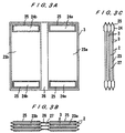
- FIGS. 3A, 3B and 3C are schematic views showing an example of a plate heat exchanger according to the present invention, and FIG. 3A is a front view, FIG. 3B is a plan view, and FIG. 3C is a side view.
- the reference numeral 3 denotes a plate
- the reference numeral 2 denotes a heat exchange element.
- the plate heat exchanger comprises three heat exchange elements.
- the heat exchange element 2 has internal spaces 23 formed into two systems 23a and 23b, and opening portions 24 (24a, 24b) at an upper side and a lower side of each of the two systems. Internal spaces of the two systems are sealed by sealing portions 26.
- the adjacent heat exchange elements 2 are connected to each other by open rising portions 25 of the opening portions 24.
- External passages 27 are formed between the adjacent elements and provided so as to communicate with the exteriors of the elements.
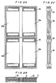
- FIGS. 4A, 4B and 4C are schematic views showing another example of a plate heat exchanger, and FIG. 4A is a front view, FIG. 4B is a plan view, and FIG. 4C is a side view.
- projections and depressions 31, 32 can be provided on the surface of the plate constituting the heat exchange element.
- the projections and depressions 32 provided on the sealing portions 26 between the two systems serve as straightening vanes for allowing vapor to speedily pass through external passages 27 outside of the heat exchange elements, and as eliminators for separating gas and liquid.
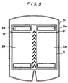
- FIG. 5 is a schematic view showing an example of a construction of the plate heat exchanger, according to the present invention, which is housed in a shell.
- spreader pipes 29 for fluids are respectively mounted on the exteriors of the heat exchange elements 2 corresponding to the internal spaces 23a, 23b of the heat exchange elements 2 housed in a shell 20.
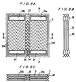
- FIGS. 6A, 6B and 6C show heat exchange elements 2 sealed at the peripheries thereof, as indicated by the reference numeral 28, instead of using the shell of FIG. 5.
- FIG. 6A is a front view
- FIG. 6B is a cross-sectional view taken along a line A-A of FIG. 6A
- FIG. 6C is a cross-sectional view taken along a line B-B of FIG. 6A.
- an inlet 33 for introducing a solution or a refrigerant, for example is provided in an upper portion.
- a solution or a refrigerant is supplied to respective units by the pipes 29 (see FIG. 5) through the inlet 33, and outlets 34, 35 for a solution or a refrigerant are separately provided at a lower portion.
- the heat exchanger is used as a condenser, it is not necessary to supply a refrigerant liquid.
- FIGS. 7A, 7B and 7C are schematic views showing another plate heat exchanger according to the present invention, and FIG. 7A is a front view, FIG. 7B is a cross-sectional view taken along a line A-A of FIG. 7A, and FIG. 7C is a cross-sectional view taken along a line B-B of FIG. 7A.
- FIGS. 8A, 8B and 8C are schematic views showing still another plate heat exchanger according to the present invention, and FIG. 8A is a front view, FIG. 8B is a cross-sectional view taken along a line A-A of FIG. 8A, and FIG. 8C is a cross-sectional view taken along a line B-B of FIG. 8A.
- the outsides of the passages for the internal fluids in the two systems of the right and left units communicate with each other in the right and left direction to thus form one system.
- the internal fluids in the right and left units are flowed in the form of two systems, and the outsides of the passages for the internal fluids are divided in a vertical direction, and the divided portions communicate with each other in the right and left direction.
- FIGS. 7 through 8 show heat exchangers having a four-stage structure.
- the divisions into the upper stages and the lower stages are performed by molded portions 36 of the plates.
- the divisions into the upper stages and the lower stages are performed by insertion of plates 37.
- the inserted plates 37 serve as not only partition plates, but also eliminators, and distributors of a liquid flowing downwardly outside of the plates 3.
- the multi-stage configuration is effective for a generator and a condenser, also.
- FIGS. 9A, 9B and 9C are schematic views showing still another example of a plate heat exchanger according to the present invention, which is an improved form of the plate heat exchanger shown in FIGS. 6A, 6B and 6C.
- four systems i.e., two right systems and two left systems, of internal fluids are formed inside of the plates. Outside of the plates, vapor passages are provided so as to communicate with the right systems and the left systems.
- FIG. 9A is a front view
- FIG. 9B is a plan view
- FIG. 9C is a side view.
- the plate heat exchanger shown in FIGS. 9A, 9B and 9C is used as a generator, a condenser, an evaporator, and an absorber of an absorption refrigerating machine, for example.
- a generator 23b and a condenser 23a are arranged on the left side and the right side of an upper portion, respectively, while an evaporator 23c and an absorber 23d are arranged on the right side and the left side of a lower portion, respectively.
- an evaporator, an absorber, a condenser, and a generator may be arranged side by side at the same height.
- main components constituting an absorption refrigerating machine can be constructed by one type of plate.
- passages in two or four systems are formed inside and outside of heat exchange elements composed of one type of plate.
- a complicated plate heat exchanger with high efficiency of heat exchanging performance for exchanging heat between two or four fluids having different temperatures can be manufactured at low cost from a small number of components by a simple manufacturing process.
- the present invention relates to a plate heat exchanger for exchanging heat between two fluids flowing alternately through adjacent fluid passages between piled plates, which is suitable for an evaporator, a low-temperature generator, a condenser, and the like of a refrigerating machine using a low-pressure refrigerant.
Landscapes
- Engineering & Computer Science (AREA)
- Physics & Mathematics (AREA)
- Thermal Sciences (AREA)
- Mechanical Engineering (AREA)
- General Engineering & Computer Science (AREA)
- Heat-Exchange Devices With Radiators And Conduit Assemblies (AREA)
Applications Claiming Priority (5)
| Application Number | Priority Date | Filing Date | Title |
|---|---|---|---|
| JP7985999 | 1999-03-24 | ||
| JP7986099 | 1999-03-24 | ||
| JP11079859A JP2000274968A (ja) | 1999-03-24 | 1999-03-24 | プレート式熱交換器 |
| JP11079860A JP2000274965A (ja) | 1999-03-24 | 1999-03-24 | プレート式熱交換器 |
| PCT/JP2000/001762 WO2000057121A1 (fr) | 1999-03-24 | 2000-03-23 | Echangeur thermique du type a plaques |
Publications (2)
| Publication Number | Publication Date |
|---|---|
| EP1085286A1 true EP1085286A1 (fr) | 2001-03-21 |
| EP1085286A4 EP1085286A4 (fr) | 2004-06-16 |
Family
ID=26420853
Family Applications (1)
| Application Number | Title | Priority Date | Filing Date |
|---|---|---|---|
| EP00911295A Withdrawn EP1085286A4 (fr) | 1999-03-24 | 2000-03-23 | Echangeur thermique du type a plaques |
Country Status (3)
| Country | Link |
|---|---|
| EP (1) | EP1085286A4 (fr) |
| CN (1) | CN1190644C (fr) |
| WO (1) | WO2000057121A1 (fr) |
Cited By (8)
| Publication number | Priority date | Publication date | Assignee | Title |
|---|---|---|---|---|
| EP1283403A2 (fr) * | 2001-08-06 | 2003-02-12 | Xenesys Inc. | Elément de transfert de chaleur et sa méthode de fabrication |
| WO2006104443A1 (fr) * | 2005-04-01 | 2006-10-05 | Alfa Laval Corporate Ab | Echangeur de chaleur a plaques |
| FR2921467A1 (fr) * | 2007-09-25 | 2009-03-27 | Peugeot Citroen Automobiles Sa | Systeme d'echange thermique a plaques destine a la desorption en continu d'une solution a contre-courant d'une phase vapeur, notamment dans une climatisation par absorption |
| WO2013131794A1 (fr) * | 2012-03-07 | 2013-09-12 | Mahle International Gmbh | Échangeur de chaleur à plaques et son procédé de production |
| DE102012107381A1 (de) * | 2012-08-10 | 2014-05-15 | Ttz Thermo Technik Zeesen Gmbh & Co. Kg | Plattenwärmeübertrager, insbesondere für Absorptionskälteanlagen |
| US20150129183A1 (en) * | 2012-04-28 | 2015-05-14 | Modine Manufacturing Company | Heat exchanger having a cooler block and production method |
| US9046310B2 (en) | 2008-09-23 | 2015-06-02 | Alfa Laval Corporate Ab | Plate heat exchanger |
| KR20220056872A (ko) * | 2019-09-13 | 2022-05-06 | 알파 라발 코포레이트 에이비 | 액체 공급물의 처리를 위한 판형 열교환기 |
Families Citing this family (6)
| Publication number | Priority date | Publication date | Assignee | Title |
|---|---|---|---|---|
| FI113695B (fi) * | 2001-10-09 | 2004-05-31 | Vahterus Oy | Hitsattu levyrakenteinen lämmönvaihdin |
| CA2384712A1 (fr) * | 2002-05-03 | 2003-11-03 | Michel St. Pierre | Echangeur thermique a passage de faisceau bride |
| EP1553379B8 (fr) * | 2004-01-08 | 2016-09-14 | SPX Dry Cooling Belgium sprl | Echangeur de chaleur pour équipement industriel |
| US8662150B2 (en) * | 2010-08-09 | 2014-03-04 | General Electric Company | Heat exchanger media pad for a gas turbine |
| CN105091654B (zh) * | 2015-08-24 | 2017-10-27 | 合肥华凌股份有限公司 | 一种板结构及具有其的蒸发器内胆和冷凝器侧板 |
| CN114543578A (zh) * | 2020-11-25 | 2022-05-27 | 广州华凌制冷设备有限公司 | 热交换器及其翅片和换热设备及空调器 |
Citations (11)
| Publication number | Priority date | Publication date | Assignee | Title |
|---|---|---|---|---|
| US4184542A (en) * | 1976-04-16 | 1980-01-22 | Hisaka Works, Ltd. | Plate type condenser |
| DE3124918A1 (de) * | 1981-06-25 | 1983-02-10 | Lendzian, Helge, Dipl.-Ing., 4600 Dortmund | Vorrichtung zum waermetausch zwischen mindestens zwei medien |
| JPS6071894A (ja) * | 1983-09-27 | 1985-04-23 | Hisaka Works Ltd | プレ−ト式熱交換器 |
| DE3511829A1 (de) * | 1985-03-30 | 1986-10-09 | Erdmann Horst | Kaeltemittelverdampfer- / -kondensatorkonstruktion |
| JPS6488099A (en) * | 1987-09-28 | 1989-04-03 | Hisaka Works Ltd | Multi-functional shell and plate type heat exchanger |
| JPH02192593A (ja) * | 1989-01-18 | 1990-07-30 | Hisaka Works Ltd | プレート式熱交換器 |
| WO1991009262A1 (fr) * | 1989-12-14 | 1991-06-27 | Mauri Kontu | Echangeur thermique |
| JPH0674672A (ja) * | 1992-08-25 | 1994-03-18 | Hisaka Works Ltd | プレート式熱交換器 |
| JPH0763441A (ja) * | 1993-08-27 | 1995-03-10 | Matsushita Electric Ind Co Ltd | 吸収式ヒートポンプ装置 |
| WO1998010233A1 (fr) * | 1996-09-04 | 1998-03-12 | Abb Power Oy | Ensemble utilise pour transferer une energie chauffante et une energie refroidissante |
| JPH10232066A (ja) * | 1997-02-19 | 1998-09-02 | Toyo Radiator Co Ltd | 蒸発器、吸収器、過冷却器等の組合せ一体型多板式熱 交換器 |
Family Cites Families (6)
| Publication number | Priority date | Publication date | Assignee | Title |
|---|---|---|---|---|
| JPS61186794A (ja) * | 1985-02-15 | 1986-08-20 | Hisaka Works Ltd | プレ−ト式熱交換器 |
| JPS62180269U (fr) * | 1986-05-02 | 1987-11-16 | ||
| JPS648063U (fr) * | 1987-06-25 | 1989-01-17 | ||
| JPH07280466A (ja) * | 1994-04-08 | 1995-10-27 | Nippondenso Co Ltd | 熱交換器 |
| JPH0894280A (ja) * | 1994-09-22 | 1996-04-12 | Zexel Corp | 積層型熱交換器 |
| JP3541092B2 (ja) * | 1995-09-22 | 2004-07-07 | 株式会社日阪製作所 | プレート式熱交換器 |
-
2000
- 2000-03-23 WO PCT/JP2000/001762 patent/WO2000057121A1/fr not_active Application Discontinuation
- 2000-03-23 EP EP00911295A patent/EP1085286A4/fr not_active Withdrawn
- 2000-03-23 CN CNB008004048A patent/CN1190644C/zh not_active Expired - Fee Related
Patent Citations (11)
| Publication number | Priority date | Publication date | Assignee | Title |
|---|---|---|---|---|
| US4184542A (en) * | 1976-04-16 | 1980-01-22 | Hisaka Works, Ltd. | Plate type condenser |
| DE3124918A1 (de) * | 1981-06-25 | 1983-02-10 | Lendzian, Helge, Dipl.-Ing., 4600 Dortmund | Vorrichtung zum waermetausch zwischen mindestens zwei medien |
| JPS6071894A (ja) * | 1983-09-27 | 1985-04-23 | Hisaka Works Ltd | プレ−ト式熱交換器 |
| DE3511829A1 (de) * | 1985-03-30 | 1986-10-09 | Erdmann Horst | Kaeltemittelverdampfer- / -kondensatorkonstruktion |
| JPS6488099A (en) * | 1987-09-28 | 1989-04-03 | Hisaka Works Ltd | Multi-functional shell and plate type heat exchanger |
| JPH02192593A (ja) * | 1989-01-18 | 1990-07-30 | Hisaka Works Ltd | プレート式熱交換器 |
| WO1991009262A1 (fr) * | 1989-12-14 | 1991-06-27 | Mauri Kontu | Echangeur thermique |
| JPH0674672A (ja) * | 1992-08-25 | 1994-03-18 | Hisaka Works Ltd | プレート式熱交換器 |
| JPH0763441A (ja) * | 1993-08-27 | 1995-03-10 | Matsushita Electric Ind Co Ltd | 吸収式ヒートポンプ装置 |
| WO1998010233A1 (fr) * | 1996-09-04 | 1998-03-12 | Abb Power Oy | Ensemble utilise pour transferer une energie chauffante et une energie refroidissante |
| JPH10232066A (ja) * | 1997-02-19 | 1998-09-02 | Toyo Radiator Co Ltd | 蒸発器、吸収器、過冷却器等の組合せ一体型多板式熱 交換器 |
Non-Patent Citations (7)
| Title |
|---|
| PATENT ABSTRACTS OF JAPAN vol. 009, no. 213 (M-408), 30 August 1985 (1985-08-30) -& JP 60 071894 A (HISAKA SEISAKUSHO:KK), 23 April 1985 (1985-04-23) * |
| PATENT ABSTRACTS OF JAPAN vol. 013, no. 299 (M-847), 11 July 1989 (1989-07-11) -& JP 01 088099 A (HISAKA WORKS LTD), 3 April 1989 (1989-04-03) * |
| PATENT ABSTRACTS OF JAPAN vol. 014, no. 478 (M-1036), 18 October 1990 (1990-10-18) -& JP 02 192593 A (HISAKA WORKS LTD), 30 July 1990 (1990-07-30) * |
| PATENT ABSTRACTS OF JAPAN vol. 018, no. 331 (M-1626), 23 June 1994 (1994-06-23) -& JP 06 074672 A (HISAKA WORKS LTD), 18 March 1994 (1994-03-18) * |
| PATENT ABSTRACTS OF JAPAN vol. 1995, no. 06, 31 July 1995 (1995-07-31) -& JP 07 063441 A (MATSUSHITA ELECTRIC IND CO LTD), 10 March 1995 (1995-03-10) * |
| PATENT ABSTRACTS OF JAPAN vol. 1998, no. 14, 31 December 1998 (1998-12-31) -& JP 10 232066 A (TOYO RADIATOR CO LTD;HONDA MOTOR CO LTD), 2 September 1998 (1998-09-02) * |
| See also references of WO0057121A1 * |
Cited By (13)
| Publication number | Priority date | Publication date | Assignee | Title |
|---|---|---|---|---|
| EP1283403A2 (fr) * | 2001-08-06 | 2003-02-12 | Xenesys Inc. | Elément de transfert de chaleur et sa méthode de fabrication |
| EP1283403A3 (fr) * | 2001-08-06 | 2004-04-07 | Xenesys Inc. | Elément de transfert de chaleur et sa méthode de fabrication |
| US7069982B2 (en) | 2001-08-06 | 2006-07-04 | Xenesys, Inc. | Heat transfer member and method for manufacturing same |
| WO2006104443A1 (fr) * | 2005-04-01 | 2006-10-05 | Alfa Laval Corporate Ab | Echangeur de chaleur a plaques |
| WO2009044033A3 (fr) * | 2007-09-25 | 2009-06-04 | Peugeot Citroen Automobiles Sa | Systeme d'echange thermique a plaques destine a la desorption en continu d'une solution a contre-courant d'une phase vapeur, notamment dans une climatisation par absorption |
| WO2009044033A2 (fr) * | 2007-09-25 | 2009-04-09 | Peugeot Citroën Automobiles SA | Systeme d'echange thermique a plaques destine a la desorption en continu d'une solution a contre-courant d'une phase vapeur, notamment dans une climatisation par absorption |
| FR2921467A1 (fr) * | 2007-09-25 | 2009-03-27 | Peugeot Citroen Automobiles Sa | Systeme d'echange thermique a plaques destine a la desorption en continu d'une solution a contre-courant d'une phase vapeur, notamment dans une climatisation par absorption |
| US9046310B2 (en) | 2008-09-23 | 2015-06-02 | Alfa Laval Corporate Ab | Plate heat exchanger |
| WO2013131794A1 (fr) * | 2012-03-07 | 2013-09-12 | Mahle International Gmbh | Échangeur de chaleur à plaques et son procédé de production |
| US20150129183A1 (en) * | 2012-04-28 | 2015-05-14 | Modine Manufacturing Company | Heat exchanger having a cooler block and production method |
| DE102012107381A1 (de) * | 2012-08-10 | 2014-05-15 | Ttz Thermo Technik Zeesen Gmbh & Co. Kg | Plattenwärmeübertrager, insbesondere für Absorptionskälteanlagen |
| DE102012107381B4 (de) | 2012-08-10 | 2022-04-07 | Ttz Thermo Technik Zeesen Gmbh & Co. Kg | Plattenwärmeübertrager, insbesondere für Absorptionskälteanlagen |
| KR20220056872A (ko) * | 2019-09-13 | 2022-05-06 | 알파 라발 코포레이트 에이비 | 액체 공급물의 처리를 위한 판형 열교환기 |
Also Published As
| Publication number | Publication date |
|---|---|
| CN1190644C (zh) | 2005-02-23 |
| WO2000057121A1 (fr) | 2000-09-28 |
| CN1297523A (zh) | 2001-05-30 |
| EP1085286A4 (fr) | 2004-06-16 |
Similar Documents
| Publication | Publication Date | Title |
|---|---|---|
| US6681844B1 (en) | Plate type heat exchanger | |
| US8550153B2 (en) | Heat exchanger and method of operating the same | |
| US11289752B2 (en) | Plate assembly for heat exchanger | |
| KR101263559B1 (ko) | 열 교환기 | |
| US20140060789A1 (en) | Heat exchanger and method of operating the same | |
| AU740183B2 (en) | Heat exchanger | |
| EP2241849B1 (fr) | Échangeur thermique micro-canal en bloc de tubes et ailettes comprenant un arrangement de tuyau reflux particulier | |
| EP1085286A1 (fr) | Echangeur thermique du type a plaques | |
| WO2007136379A1 (fr) | Échangeur de chaleur à tube plat en spirale | |
| CN107664444B (zh) | 侧流程板壳式换热板以及多流程可拆卸板壳式换热器 | |
| EP1563240B1 (fr) | Echangeur thermique a haute pression | |
| US20130087317A1 (en) | Internal heat exchanger with external manifolds | |
| KR101458523B1 (ko) | 기액 분리형 판형 열교환기 | |
| KR100497847B1 (ko) | 증발기 | |
| JP2013122368A (ja) | 車両用熱交換器 | |
| KR20130065174A (ko) | 차량용 열교환기 | |
| KR100522668B1 (ko) | 열교환기튜브 | |
| EP3470762A1 (fr) | Échangeur de chaleur à plaques | |
| JPH10300260A (ja) | 吸収冷温水機 | |
| JP2004183960A (ja) | 熱交換器 | |
| RU2094726C1 (ru) | Пластинчатый теплообменник | |
| KR20020078806A (ko) | 열교환기 | |
| JP2000274965A (ja) | プレート式熱交換器 | |
| KR100545273B1 (ko) | 열교환기 및 열교환기의 냉각장치 | |
| JP2000274968A (ja) | プレート式熱交換器 |
Legal Events
| Date | Code | Title | Description |
|---|---|---|---|
| PUAI | Public reference made under article 153(3) epc to a published international application that has entered the european phase |
Free format text: ORIGINAL CODE: 0009012 |
|
| 17P | Request for examination filed |
Effective date: 20001201 |
|
| AK | Designated contracting states |
Kind code of ref document: A1 Designated state(s): AT BE CH CY DE DK ES FI FR GB GR IE IT LI LU MC NL PT SE |
|
| RIC1 | Information provided on ipc code assigned before grant |
Ipc: 7F 28D 9/00 A |
|
| RBV | Designated contracting states (corrected) |
Designated state(s): DE FR IT SE |
|
| A4 | Supplementary search report drawn up and despatched |
Effective date: 20040426 |
|
| 17Q | First examination report despatched |
Effective date: 20051222 |
|
| STAA | Information on the status of an ep patent application or granted ep patent |
Free format text: STATUS: THE APPLICATION IS DEEMED TO BE WITHDRAWN |
|
| 18D | Application deemed to be withdrawn |
Effective date: 20061130 |