EP1085190B1 - Verfahren und Vorrichtung zum Laden wenigstens eines kapazitiven Stellgliedes - Google Patents
Verfahren und Vorrichtung zum Laden wenigstens eines kapazitiven Stellgliedes Download PDFInfo
- Publication number
- EP1085190B1 EP1085190B1 EP00119669A EP00119669A EP1085190B1 EP 1085190 B1 EP1085190 B1 EP 1085190B1 EP 00119669 A EP00119669 A EP 00119669A EP 00119669 A EP00119669 A EP 00119669A EP 1085190 B1 EP1085190 B1 EP 1085190B1
- Authority
- EP
- European Patent Office
- Prior art keywords
- capacitor
- charging
- charge transfer
- actuator
- diode
- Prior art date
- Legal status (The legal status is an assumption and is not a legal conclusion. Google has not performed a legal analysis and makes no representation as to the accuracy of the status listed.)
- Expired - Lifetime
Links
- 238000000034 method Methods 0.000 title claims description 23
- 239000003990 capacitor Substances 0.000 claims description 48
- 238000007599 discharging Methods 0.000 claims description 4
- 238000002347 injection Methods 0.000 description 20
- 239000007924 injection Substances 0.000 description 20
- 239000000446 fuel Substances 0.000 description 17
- 238000002485 combustion reaction Methods 0.000 description 11
- 238000010586 diagram Methods 0.000 description 3
- 230000001934 delay Effects 0.000 description 1
- 210000005069 ears Anatomy 0.000 description 1
- 230000005611 electricity Effects 0.000 description 1
- 238000005516 engineering process Methods 0.000 description 1
- 230000002028 premature Effects 0.000 description 1
- 239000007787 solid Substances 0.000 description 1
- 230000001550 time effect Effects 0.000 description 1
Images

Classifications
-
- H—ELECTRICITY
- H02—GENERATION; CONVERSION OR DISTRIBUTION OF ELECTRIC POWER
- H02N—ELECTRIC MACHINES NOT OTHERWISE PROVIDED FOR
- H02N2/00—Electric machines in general using piezoelectric effect, electrostriction or magnetostriction
- H02N2/02—Electric machines in general using piezoelectric effect, electrostriction or magnetostriction producing linear motion, e.g. actuators; Linear positioners ; Linear motors
- H02N2/06—Drive circuits; Control arrangements or methods
- H02N2/065—Large signal circuits, e.g. final stages
- H02N2/067—Large signal circuits, e.g. final stages generating drive pulses
-
- F—MECHANICAL ENGINEERING; LIGHTING; HEATING; WEAPONS; BLASTING
- F02—COMBUSTION ENGINES; HOT-GAS OR COMBUSTION-PRODUCT ENGINE PLANTS
- F02D—CONTROLLING COMBUSTION ENGINES
- F02D41/00—Electrical control of supply of combustible mixture or its constituents
- F02D41/20—Output circuits, e.g. for controlling currents in command coils
- F02D41/2096—Output circuits, e.g. for controlling currents in command coils for controlling piezoelectric injectors
-
- F—MECHANICAL ENGINEERING; LIGHTING; HEATING; WEAPONS; BLASTING
- F02—COMBUSTION ENGINES; HOT-GAS OR COMBUSTION-PRODUCT ENGINE PLANTS
- F02D—CONTROLLING COMBUSTION ENGINES
- F02D41/00—Electrical control of supply of combustible mixture or its constituents
- F02D41/20—Output circuits, e.g. for controlling currents in command coils
- F02D2041/2003—Output circuits, e.g. for controlling currents in command coils using means for creating a boost voltage, i.e. generation or use of a voltage higher than the battery voltage, e.g. to speed up injector opening
- F02D2041/2006—Output circuits, e.g. for controlling currents in command coils using means for creating a boost voltage, i.e. generation or use of a voltage higher than the battery voltage, e.g. to speed up injector opening by using a boost capacitor
-
- F—MECHANICAL ENGINEERING; LIGHTING; HEATING; WEAPONS; BLASTING
- F02—COMBUSTION ENGINES; HOT-GAS OR COMBUSTION-PRODUCT ENGINE PLANTS
- F02D—CONTROLLING COMBUSTION ENGINES
- F02D41/00—Electrical control of supply of combustible mixture or its constituents
- F02D41/20—Output circuits, e.g. for controlling currents in command coils
- F02D2041/202—Output circuits, e.g. for controlling currents in command coils characterised by the control of the circuit
- F02D2041/2041—Output circuits, e.g. for controlling currents in command coils characterised by the control of the circuit for controlling the current in the free-wheeling phase
Definitions
- the invention relates to a method for loading at least one capacitive actuator, in particular a fuel injection valve an internal combustion engine.
- the invention relates also an apparatus for performing this method.
- the Fuel quantity divided into pre and main injection quantity what slower combustion and thus a reduction in combustion noise allows.
- the actuators are so far with a constant loading and unloading time (duration of the reloading from an energy source to the actuator or vice versa) controlled, which must be very short (for example 100 ⁇ s), so that a predetermined fuel pre-injection quantity also in the highest load or speed range of the internal combustion engine can still be injected.
- the loading process takes place, for example, as a reversing process the charge from a charge source (a series connection of a Charging and a charge capacitor) via a charge coil to the actuator, the inductance of the recharging coil together with the capacities of the capacitors and the actuator the time constant for charging and discharging (the Charging and discharging time).
- a charge source a series connection of a Charging and a charge capacitor
- the inductance of the recharging coil together with the capacities of the capacitors and the actuator the time constant for charging and discharging (the Charging and discharging time).
- the inventive method is that to achieve shorter loading times (and thus lower injection quantities) which during the charging process of the capacitive actuator in that of capacitors, charge transfer coil and capacitive actuator existing resonant circuit current flowing into a freewheeling circuit is redirected, making the loading process essential is shortened.
- the duration of the charging time applies limits the minimum fuel injection duration. This is particularly critical at high injection pressures because the amount of fuel injected for the same injection duration increases with the fuel pressure proportional to the load. to Achieving a certain injection quantity, especially one low pre-injection quantity, are therefore with increasing fuel pressure shorter and shorter injection times required.
- the injection quantities are depending on load or pressure.
- the load When the load is low, they become small Injection quantities required, but with large loads, large injection quantities at high fuel pressure. This correlation between fuel quantity and fuel pressure enables the Using longer loading times for the main injection too in the high load range.
- Different loading times of a capacitive actuator have within certain limits, for example between 100 ⁇ s and 200 ⁇ s, except for dead time effects (delays of Injection start and end) caused by a time shift the control signals can be compensated, no influence on the injection process relevant for a combustion process.
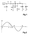
- the basic circuit of a known device for Loading and unloading a capacitive actuator P according to the figure 1 - with the exception of the two diodes D3 and D4 from a ground potential connected on both sides Series connection of a charge source (here one of one Energy source V chargeable charging capacitor C1 and a recharging capacitor C2), a charging switch S1, a first one Diode D1, a recharge coil L and one or more parallel connected Actuators P, P ', with each actuator P, P 'a selection switch S, S' connected in series is.
- the connection of the recharging capacitor leading to the charging switch S1 C2 is in via a second diode D2 Discharge switch S2 in series with ground reference potential GND connectable.
- the two switches S1 and S2 are one Control circuit ST controlled, which is not shown is.
- the capacitance of the charging capacitor C1 is essential larger than that of the recharging capacitor C2: C1 »C2.
- discharge or selection switches is preferably to be understood as switches, which are switched on or off, for example Thyristors, or MOSFETs (with a diode connected in series, if the current flow is only in one direction may).
- An actuator P is loaded in this known one Switching by switching the charging switch S1 and the the selection switch S assigned to the actuator at the time t0 ( Figure 2).
- the capacitor C1 swings beforehand and C2 supplied charge with a current I in the form of a half Sinusoidal wave (solid curve in Figure 2) of these two capacitors via the transfer coil L to the actuator P.
- the actuator voltage U rises to a certain value, and the actuator P opens it Fuel injector.
- the Charge switch S1 and selector switch S simultaneously conductive controlled, whereby the actuator P from the previously loaded Capacitors C1 and C2 charged via the recharge coil L. and a sinusoidal current I through the actuator P to begins to flow.
- the charge switch S1 is prematurely non-conductive at time t1 controlled.
- This will now complete the circuit of the transfer coil L flowing current I via the actuator P and the fourth diode D4 closed, whereby the current I (dashed Curve) drops rapidly and already at time t2 becomes zero.
- a freewheel for the Transloading coil L measure is shortened the loading time; it only has the duration t2 - t0.
- the end of the Charging time beginning at time t0 can be between t1 and t3 vary, resulting in loading times from 100 ⁇ s to at the selected maximum, here 200 ⁇ s.
- the actuator P is unloaded, as already described above, starting at time t4 and ending at time t5.
- the respective selection switch, S or S ' must be at least from Start (t0) of the charging time until the end of the discharge time (t5) to be a leader.
- FIG 3 shows the basic circuit of a second embodiment according to the invention, which differs from the Circuit according to Figure 1 differs in that with the fourth diode D4 a fifth diode D5 with the same current conduction direction is connected in series, over a Switch S3 can be connected to the charging capacitor C1, and that between the fourth diode D4 and the charge capacitor C2 another capacitor C3 is connected.
- This circuit allows at least one Part of charging at the moment of premature termination energy stored in the transfer coil L further Capacitor C3, what the freewheel and thus accelerating the loading process is accelerated.
- the actuator P is the buffered Energy stored in the charging capacitor C1, as explained below.
- the loading process takes place as in the exemplary embodiment Figure 1.
- the charge switch S1 becomes conductive controlled, whereby the actuator P from the series circuit of the charging capacitor C1 and the recharging capacitor C2 the charge coil L is charged and a sinusoidal current I by the actuator P, which by the selector switch S selected, begins to flow.
- the loading process not interrupted, it ends at time t3.
- the charging switch is used to achieve a shorter charging time S1 is controlled prematurely again at time t1.
- the current flows from the transfer coil from this point in time L to actuator P and from it via the selector switch S, the fourth diode D4 and the further capacitor C3 back to the transfer coil L until this current at time t2 becomes zero (dashed curve from t1 to t2 in FIG. 4).
- further Capacitor C3 in which the part of the in the transfer coil L stored energy, which is not stored in the actuator is temporarily stored, there is a resonant circuit with a different time constant, which is determined by the capacity of the further capacitor C3 can be influenced. This will the loading time of the actuator ends faster than that Exemplary embodiment according to FIG. 1.
- the initial conditions are fulfilled for the next actuator charge: the voltage at the charge capacitor C2 is equal to the voltage at the charge capacitor C1, and the further capacitor C3 is not charged.
Description
- Figur 1
- ein erstes Ausführungsbeispiel nach der Erfindung,
- Figur 2
- ein Diagramm der Lade- und Entladeströme des Ausführungsbeispiels nach Figur 1,
- Figur 3
- ein zweites Ausführungsbeispiel nach der Erfindung, und
- Figur 4
- ein Diagramm der Lade- und Entladeströme des Ausführungsbeispiels nach Figur 3.
Claims (5)
- Verfahren zum Laden wenigstens eines kapazitiven Stellgliedes (P, P'). mittels eines Schwingkreises, der aus einer kapazitiven Ladungsquelle (C1, C2), einer Umladespule (L), und dem wenigstens einen Stellglied (P, P') besteht,
dadurch gekennzeichnet,daß die Kapazität (C1 + C2) der Ladungsquelle für eine vorgegebene maximale Ladezeit (t3 - t0) bemessen ist, unddaß zur Erzielung einer kürzeren Ladezeit (t2 - t0) der Schwingkreis vorzeitig zu einem bestimmten Zeitpunkt (t1) nach Beginn (t0) des Ladevorgangs aufgetrennt und in einen Freilaufkreis, der die Umladespule (L) und das Stellglied (P, P') enthält, umgeschaltet wird. - Vorrichtung zur Durchführung des Verfahrens nach Anspruch 1, mit einer Reihenschaltung einer Ladungsquelle, welche aus einem von einer Energiequelle (V) ladbaren Ladekondensator (C1) und einem Umladekondensator (C2) besteht, eines Ladeschalters (S1), einer ersten Diode (D1), einer Umladespule (L) und dem Stellglied (P, P'), und mit einem Entladeschalter (S2), der den Verbindungspunkt von erster Diode (D1) und Umladekondensator (C2) über eine zweite Diode (D2) mit einem Bezugspotential (GND) verbindet, wobei die zweite Diode (D2) zum Bezugspotential (GND) hin stromleitend ist,
dadurch gekennzeichnet,daß parallel zum Umladekondensator (C2) eine in Richtung zum Stellglied (P, P') hin stromleitende dritte Diode (D3) angeordnet ist, unddaß zwischen dem Bezugspotential (GND) und dem Verbindungspunkt von Umladekondensator (C2) und Umladespule (L) eine vom Bezugspotential (GND) in Richtung zur Umladespule (L) hin stromleitende vierte Diode (D4) angeordnet ist. - Vorrichtung nach Anspruch 2, dadurch gekennzeichnet,daß zwischen der vierten Diode (D4) und dem Verbindungspunkt von Umladekondensator (C2) und Umladespule (L) ein weiterer Kondensator (C3) angeordnet ist, unddaß eine fünfte Diode (D5) vorgesehen ist, die in Reihe mit der vierten Diode (D4) liegt und über einen weiteren Schalter (S3) mit dem Ladekondensator (C1) verbindbar ist.
- Vorrichtung nach Anspruch 3, dadurch gekennzeichnet,daß der weitere Schalter (S3) synchron mit dem Entladeschalter (S2) leitend und nichtleitend gesteuert wird.
- Vorrichtung nach Anspruch 3, dadurch gekennzeichnet,daß die Kapazität des Ladekondensators (C1) wesentlich größer als die des Umladekondensators (C2) und die Kapazität des weiteren Kondensators (C3) kleiner als die des Umladekondensators (C2) gewählt ist.
Applications Claiming Priority (2)
| Application Number | Priority Date | Filing Date | Title |
|---|---|---|---|
| DE19944734 | 1999-09-17 | ||
| DE19944734A DE19944734B4 (de) | 1999-09-17 | 1999-09-17 | Verfahren und Vorrichtung zum Laden wenigstens eines kapazitiven Stellgliedes |
Publications (3)
| Publication Number | Publication Date |
|---|---|
| EP1085190A2 EP1085190A2 (de) | 2001-03-21 |
| EP1085190A3 EP1085190A3 (de) | 2003-05-28 |
| EP1085190B1 true EP1085190B1 (de) | 2004-04-07 |
Family
ID=7922451
Family Applications (1)
| Application Number | Title | Priority Date | Filing Date |
|---|---|---|---|
| EP00119669A Expired - Lifetime EP1085190B1 (de) | 1999-09-17 | 2000-09-08 | Verfahren und Vorrichtung zum Laden wenigstens eines kapazitiven Stellgliedes |
Country Status (3)
| Country | Link |
|---|---|
| US (1) | US6435162B1 (de) |
| EP (1) | EP1085190B1 (de) |
| DE (2) | DE19944734B4 (de) |
Families Citing this family (14)
| Publication number | Priority date | Publication date | Assignee | Title |
|---|---|---|---|---|
| DE19944733B4 (de) * | 1999-09-17 | 2007-01-04 | Siemens Ag | Vorrichtung zum Ansteuern wenigstens eines kapazitiven Stellgliedes |
| EP1138902B1 (de) * | 2000-04-01 | 2005-04-06 | Robert Bosch GmbH | Verfahren und Vorrichtung zur zeitgesteuerter Spannungsmessung über einer Vorrichtung in einem Ladungskreis eines piezoelektrischen Element |
| DE10017367B4 (de) | 2000-04-07 | 2006-12-28 | Siemens Ag | Verfahren und Vorrichtung zum Ansteuern wenigstens eines kapazitiven Stellgliedes |
| DE10028353C2 (de) * | 2000-06-08 | 2003-02-20 | Siemens Ag | Verfahren zur Überprüfung eines kapazitiven Stellgliedes |
| DE10113802B4 (de) | 2001-03-21 | 2007-10-18 | Siemens Ag | Vorrichtung zum Ansteuern eines piezoelektrischen Stellgliedes |
| DE10149671A1 (de) * | 2001-10-09 | 2003-04-24 | Eppendorf Ag | Verfahren zum Steuern eines Piezoantriebes und Piezoantrieb zur Durchführung des Verfahrens |
| DE10223553B4 (de) * | 2002-05-27 | 2004-08-05 | Siemens Ag | Verfahren zur Ansteuerung eines Aktors und zugehörige Steuereinrichtung |
| EP1400676B1 (de) * | 2002-09-23 | 2009-12-16 | Delphi Technologies, Inc. | Treiberschaltung für eine Kraftstoff-Einspritzdüse |
| US6760212B2 (en) * | 2002-09-23 | 2004-07-06 | Delphi Technologies, Inc. | Piezoelectric injector drive circuit |
| ATE395999T1 (de) * | 2004-07-02 | 2008-06-15 | Sauer Gmbh | Schwingkopf-werkzeug |
| DE102004047961A1 (de) * | 2004-10-01 | 2006-05-18 | Siemens Ag | Vorrichtung und Verfahren zum Ansteuern eines Piezoaktors |
| AT503441B1 (de) | 2006-05-24 | 2007-10-15 | Steinbauer Electronics Dev Gmb | Vorrichtung zum ansteuern wenigstens eines piezoelektrischen stelltriebes einer einspritzdüse für eine brennkraftmaschine |
| CN104373235B (zh) * | 2014-12-03 | 2016-08-17 | 中国第一汽车股份有限公司无锡油泵油嘴研究所 | 高压共轨压电执行器驱动电流控制电路 |
| DE102022129371B3 (de) | 2022-11-07 | 2024-03-21 | OQmented GmbH | Schaltung mit aufwärtswandler zur ansteuerung eines aktuators zum antrieb einer schwingungsbewegung in einem mems |
Family Cites Families (7)
| Publication number | Priority date | Publication date | Assignee | Title |
|---|---|---|---|---|
| JP2855648B2 (ja) * | 1989-04-28 | 1999-02-10 | トヨタ自動車株式会社 | 内燃機関の燃料噴射制御装置 |
| DE19632837A1 (de) * | 1996-08-14 | 1998-02-19 | Siemens Ag | Vorrichtung und Verfahren zum Ansteuern wenigstens eines kapazitiven Stellgliedes |
| DE19632872C2 (de) * | 1996-08-14 | 1998-08-13 | Siemens Ag | Vorrichtung und Verfahren zum Ansteuern eines kapazitiven Stellgliedes |
| DE19652801C1 (de) * | 1996-12-18 | 1998-04-23 | Siemens Ag | Verfahren und Vorrichtung zum Ansteuern wenigstens eines kapazitiven Stellgliedes |
| DE19723932C1 (de) * | 1997-06-06 | 1998-12-24 | Siemens Ag | Verfahren zum Ansteuern wenigstens eines kapazitiven Stellgliedes |
| DE19733560B4 (de) * | 1997-08-02 | 2007-04-05 | Robert Bosch Gmbh | Verfahren und Vorrichtung zum Laden und Entladen eines piezoelektrischen Elements |
| DE19854789A1 (de) * | 1998-02-10 | 1999-08-12 | Bosch Gmbh Robert | Verfahren und Vorrichtung zum Laden und Entladen eines piezoelektrischen Elements |
-
1999
- 1999-09-17 DE DE19944734A patent/DE19944734B4/de not_active Expired - Fee Related
-
2000
- 2000-09-08 DE DE50005963T patent/DE50005963D1/de not_active Expired - Lifetime
- 2000-09-08 EP EP00119669A patent/EP1085190B1/de not_active Expired - Lifetime
- 2000-09-18 US US09/665,250 patent/US6435162B1/en not_active Expired - Fee Related
Also Published As
| Publication number | Publication date |
|---|---|
| DE19944734A1 (de) | 2001-04-05 |
| EP1085190A3 (de) | 2003-05-28 |
| DE50005963D1 (de) | 2004-05-13 |
| US6435162B1 (en) | 2002-08-20 |
| EP1085190A2 (de) | 2001-03-21 |
| DE19944734B4 (de) | 2007-02-15 |
Similar Documents
| Publication | Publication Date | Title |
|---|---|---|
| EP1192345B1 (de) | Verfahren und vorrichtung zum laden eines kapazitiven stellgliedes | |
| EP0704097B1 (de) | Vorrichtung und ein verfahren zur ansteuerung eines elektromagnetischen verbrauchers | |
| EP1085190B1 (de) | Verfahren und Vorrichtung zum Laden wenigstens eines kapazitiven Stellgliedes | |
| EP1792069B1 (de) | Schaltungsanordnung und verfahren zum laden und entladen wenigstens einer kapazitiven last | |
| DE19652801C1 (de) | Verfahren und Vorrichtung zum Ansteuern wenigstens eines kapazitiven Stellgliedes | |
| EP0946998B1 (de) | Vorrichtung und verfahren zum ansteuern wenigstens eines kapazitiven stellgliedes | |
| EP0934605A1 (de) | Verfahren und vorrichtung zum ansteuern eines kapazitiven stellgliedes | |
| DE19944733A1 (de) | Vorrichtung zum Ansteuern wenigstens eines kapazitiven Stellgliedes | |
| EP0944925A1 (de) | Vorrichtung und verfahren zum ansteuern eines kapazitiven stellgliedes | |
| EP1269000B1 (de) | Verfahren und vorrichtung zum ansteuern wenigstens eines kapazitiven stellgliedes | |
| EP1099260B1 (de) | Verfahren und vorrichtung zum ansteuern wenigstens eines kapazitiven stellgliedes | |
| DE2300177A1 (de) | Schaltungsanordnung fuer die erwaermungs-brennstoffanreicherung bei einem elektronischen brennstoffeinspritzsystem | |
| EP0947000B1 (de) | Verfahren und vorrichtung zum ansteuern wenigstens eines kapazitiven stellgliedes | |
| EP2129897B1 (de) | Ansteuerschaltung und ansteuerverfahren für ein piezoelektrisches element | |
| DE102006060311A1 (de) | Verfahren zum Betrieb eines Einspritzventils | |
| DE102005016279B4 (de) | Schaltungsanordnung und Verfahren zum Betätigen eines auf- und entladbaren, elektromechanischen Stellgliedes | |
| DE19823850C2 (de) | Vorrichtung zur Ansteuerung eines elektromagnetischen Verbrauchers | |
| EP0854281B1 (de) | Verfahren und Vorrichtung zur Ansteuerung wenigstens eines elektromagnetischen Verbrauchers | |
| DE19709715A1 (de) | Vorrichtung und Verfahren zum Ansteuern wenigstens eines kapazitiven Stellgliedes | |
| DE19826037C2 (de) | Verfahren und Vorrichtung zur Ansteuerung wenigstens eines Verbrauchers | |
| DE10328623B4 (de) | Konverterschaltung und Brennkraftmaschine | |
| DE19931234C1 (de) | Verfahren zum Ansteuern eines kapazitiven Stellgliedes eines Kraftstoffeinspritzventils einer Brennkraftmaschine | |
| DE102006004766B4 (de) | Elektrische Schaltung zum Betreiben eines Piezoaktors einer Kraftstoffeinspritzeinspritzeinrichtung einer Brennkraftmaschine | |
| DE2305507C3 (de) | Elektronisches Brennstoffsteuersystem für eine Brennkraftmaschine | |
| DE102012105773A1 (de) | Elektronische Steuereinheit für ein Kraftstoffeinspritzsystem |
Legal Events
| Date | Code | Title | Description |
|---|---|---|---|
| PUAI | Public reference made under article 153(3) epc to a published international application that has entered the european phase |
Free format text: ORIGINAL CODE: 0009012 |
|
| AK | Designated contracting states |
Kind code of ref document: A2 Designated state(s): AT BE CH CY DE DK ES FI FR GB GR IE IT LI LU MC NL PT SE |
|
| AX | Request for extension of the european patent |
Free format text: AL;LT;LV;MK;RO;SI |
|
| PUAL | Search report despatched |
Free format text: ORIGINAL CODE: 0009013 |
|
| AK | Designated contracting states |
Designated state(s): AT BE CH CY DE DK ES FI FR GB GR IE IT LI LU MC NL PT SE |
|
| AX | Request for extension of the european patent |
Extension state: AL LT LV MK RO SI |
|
| 17P | Request for examination filed |
Effective date: 20030707 |
|
| GRAP | Despatch of communication of intention to grant a patent |
Free format text: ORIGINAL CODE: EPIDOSNIGR1 |
|
| GRAS | Grant fee paid |
Free format text: ORIGINAL CODE: EPIDOSNIGR3 |
|
| AKX | Designation fees paid |
Designated state(s): DE FR GB IT |
|
| GRAA | (expected) grant |
Free format text: ORIGINAL CODE: 0009210 |
|
| AK | Designated contracting states |
Kind code of ref document: B1 Designated state(s): DE FR GB IT |
|
| REG | Reference to a national code |
Ref country code: GB Ref legal event code: FG4D Free format text: NOT ENGLISH |
|
| GBT | Gb: translation of ep patent filed (gb section 77(6)(a)/1977) |
Effective date: 20040407 |
|
| REF | Corresponds to: |
Ref document number: 50005963 Country of ref document: DE Date of ref document: 20040513 Kind code of ref document: P |
|
| REG | Reference to a national code |
Ref country code: IE Ref legal event code: FG4D Free format text: GERMAN |
|
| PG25 | Lapsed in a contracting state [announced via postgrant information from national office to epo] |
Ref country code: GB Free format text: LAPSE BECAUSE OF NON-PAYMENT OF DUE FEES Effective date: 20040908 |
|
| REG | Reference to a national code |
Ref country code: IE Ref legal event code: FD4D |
|
| ET | Fr: translation filed | ||
| PLBE | No opposition filed within time limit |
Free format text: ORIGINAL CODE: 0009261 |
|
| STAA | Information on the status of an ep patent application or granted ep patent |
Free format text: STATUS: NO OPPOSITION FILED WITHIN TIME LIMIT |
|
| 26N | No opposition filed |
Effective date: 20050110 |
|
| GBPC | Gb: european patent ceased through non-payment of renewal fee |
Effective date: 20040908 |
|
| REG | Reference to a national code |
Ref country code: FR Ref legal event code: TP |
|
| PGFP | Annual fee paid to national office [announced via postgrant information from national office to epo] |
Ref country code: DE Payment date: 20120930 Year of fee payment: 13 |
|
| PGFP | Annual fee paid to national office [announced via postgrant information from national office to epo] |
Ref country code: FR Payment date: 20121010 Year of fee payment: 13 |
|
| PGFP | Annual fee paid to national office [announced via postgrant information from national office to epo] |
Ref country code: IT Payment date: 20120926 Year of fee payment: 13 |
|
| REG | Reference to a national code |
Ref country code: DE Ref legal event code: R119 Ref document number: 50005963 Country of ref document: DE Effective date: 20140401 |
|
| REG | Reference to a national code |
Ref country code: FR Ref legal event code: ST Effective date: 20140530 |
|
| PG25 | Lapsed in a contracting state [announced via postgrant information from national office to epo] |
Ref country code: FR Free format text: LAPSE BECAUSE OF NON-PAYMENT OF DUE FEES Effective date: 20130930 Ref country code: DE Free format text: LAPSE BECAUSE OF NON-PAYMENT OF DUE FEES Effective date: 20140401 Ref country code: IT Free format text: LAPSE BECAUSE OF NON-PAYMENT OF DUE FEES Effective date: 20130908 |