EP1083744A2 - Anzeigevorrichtung, Signalsender/Empfängergerät und Funkübertragungsgerät - Google Patents
Anzeigevorrichtung, Signalsender/Empfängergerät und Funkübertragungsgerät Download PDFInfo
- Publication number
- EP1083744A2 EP1083744A2 EP00307648A EP00307648A EP1083744A2 EP 1083744 A2 EP1083744 A2 EP 1083744A2 EP 00307648 A EP00307648 A EP 00307648A EP 00307648 A EP00307648 A EP 00307648A EP 1083744 A2 EP1083744 A2 EP 1083744A2
- Authority
- EP
- European Patent Office
- Prior art keywords
- signal
- electronic equipment
- control
- unit
- pieces
- Prior art date
- Legal status (The legal status is an assumption and is not a legal conclusion. Google has not performed a legal analysis and makes no representation as to the accuracy of the status listed.)
- Withdrawn
Links
Images
Classifications
-
- G—PHYSICS
- G09—EDUCATION; CRYPTOGRAPHY; DISPLAY; ADVERTISING; SEALS
- G09G—ARRANGEMENTS OR CIRCUITS FOR CONTROL OF INDICATING DEVICES USING STATIC MEANS TO PRESENT VARIABLE INFORMATION
- G09G5/00—Control arrangements or circuits for visual indicators common to cathode-ray tube indicators and other visual indicators
-
- H—ELECTRICITY
- H04—ELECTRIC COMMUNICATION TECHNIQUE
- H04N—PICTORIAL COMMUNICATION, e.g. TELEVISION
- H04N5/00—Details of television systems
- H04N5/38—Transmitter circuitry for the transmission of television signals according to analogue transmission standards
-
- H—ELECTRICITY
- H04—ELECTRIC COMMUNICATION TECHNIQUE
- H04N—PICTORIAL COMMUNICATION, e.g. TELEVISION
- H04N7/00—Television systems
- H04N7/20—Adaptations for transmission via a GHz frequency band, e.g. via satellite
Definitions
- the present invention relates to display apparatus, signal transmitting and receiving apparatus and radio transmission apparatus, for example in the context of a display unit such as a television receiver and a liquid-crystal display unit.
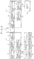
- Fig. 2 of the accompanying drawings is a diagram showing the configuration of a typical radio transmission apparatus 1.
- the radio transmission apparatus 1 is explained by referring to Fig. 2.
- the radio transmission apparatus 1 comprises a signal transmitting apparatus 1A and a signal receiving apparatus 1B.
- the signal transmitting apparatus 1A comprises components including a signal processing unit 2, a modulation unit 3, a frequency changing unit 4, a frequency synthesizing unit 5, a power amplifier 6 and a transmission antenna 7.
- the signal processing unit 2 comprises components including a buffer amplifier and a filter.
- the signal processing unit 2 sets the amplitudes of a video signal VS and an audio signal AS received from pieces of electronic equipment 8a to 8c at levels proper for modulation.
- Examples of the pieces of electronic equipment 8a to 8c are an audio tape recorder, an optical-disc drive and a digital CS tuner, which each supply a signal VS and a signal AS to a selector unit 9.
- the selector unit 9 selects one of the pieces of electronic equipment 8a to 8c, passing on a video signal VS and an audio signal AS received from the selected piece of electronic equipment to the signal processing unit 2.
- the modulation unit 3 modulates a carrier based on a frequency of an IF (Intermediate Frequency) signal received from the frequency synthesizing unit 5.
- the frequency changing unit 4 mixes the IF signal received from the modulation unit 3 with a signal with a locally generated frequency received from the frequency synthesizing unit 5 to generate an RF signal.
- the power amplifier 6 amplifies the RF signal received from the frequency changing unit 4 to a signal with a prescribed power.
- the transmission antenna 7 has a function for transmitting the amplified RF signal to the outside world. That is, the transmission antenna 7 transmits the audio signal AS and the video signal VS, which were converted into the RF signal, to the outside world.
- the signal receiving unit 1B comprises components including a reception antenna 10, a low-noise amplifier 11, a frequency changing unit 12, a demodulation unit 13, a frequency synthesizing unit 14 and a signal processing unit 15.
- the reception antenna 10 receives the RF signal from the transmission antenna 7.
- the low-noise amplifier 11 has a function to amplify the RF signal received by the reception antenna 10.
- the frequency changing unit 12 mixes the amplified RF signal with a signal having a locally generated frequency from the frequency synthesizing unit 14 to generate an IF signal.
- the demodulation unit 13 has a function to demodulate the IF signal by using a carrier with a frequency generated by the frequency synthesizing unit 14 to produce the audio signal AS and the video signal VS.
- the signal processing unit 15 removes noises included in the audio signal AS and the video signal VS, amplifies the signals and displays the amplified signals on a display unit 20.
- Examples of the display unit 20 are a television receiver and an LCD unit, which each have a function to generate a picture based on the video signal VS and to output a sound based on the audio signal AS.
- the piece of electronic equipment 8a, 8b or 8c outputs the video signal VS and the audio signal AS to the selector unit 9. Then, the selector unit 9 selects one of the pieces of electronic equipment 8a to 8c, passing on the video signal VS and the audio signal AS received from the selected piece of electronic equipment to the signal processing unit 2.
- the video signal VS and the audio signal AS are processed by the signal processing unit 2, the modulation unit 3 and the frequency changing unit 4, being converted into an RF signal, which is then amplified by the power amplifier 6 before being output as an electric wave from the transmission antenna 7.
- the RF signal is received by the reception antenna 10 and processed by the low-noise amplifier 11, the frequency changing unit 12 and the demodulation unit 13, being demodulated into the VS signal and AS signal. Then, the VS signal and the AS signal are supplied to the display unit 20, being output as an image and a sound respectively.
- the radio transmission apparatus 1 shown in Fig. 2 to change an image and a sound output by the signal processing unit 20, it is necessary to carry out predetermined operations on the piece of electronic equipment 8a, 8b of 8c.
- the signal transmitting apparatus 1A, the signal receiving apparatus 1B and the pieces of electronic equipment 8a to 8c are placed at locations separated from each other, there will be raised a problem of a need to operate the signal receiving apparatus 1B and the pieces of electronic equipment 8a to 8c frequently.
- the signal transmitting apparatus 1A and the signal receiving apparatus 1B are placed at different rooms. A problem encountered in this case is that it is difficult to operate the pieces of electronic equipment 8a to 8c and the selector unit 9 by using an infrared remote controller from the room in which the signal receiving apparatus 1B is placed.
- the display apparatus 20 is installed at a location different from that of the signal receiving apparatus 1B, the number of cables connecting the display apparatus 20 to the signal receiving apparatus 1B will increase, raising a problem of cabling complexity.
- a display apparatus for outputting an image and a sound based on a video signal and an audio signal from a display unit and an audio output unit respectively, said display apparatus is characterized by comprising:
- a video signal and an audio signal received by an antenna may be subjected to signal processing in a control unit to output an image and a sound to a display unit and an audio output unit respectively.
- an antenna transmits a control signal received by a control-signal receiving unit.
- a signal transmitting and receiving apparatus comprising:
- a control unit may process a video signal and an audio signal received from electronic equipment and an antenna transmits the processed video and audio signals.
- the antenna receives a control signal, supplying the signal to the control unit.
- the control unit controls the operation of the electronic equipment in accordance with the control signal received from the antenna.
- control of the operation of the electronic equipment based on a control signal makes it unnecessary to operate the electronic equipment directly.
- the control unit is capable of executing control of the pieces of electronic equipment in a centralized manner.
- a radio transmission apparatus comprising:
- a display apparatus may receive a video signal and an audio signal generated by electronic equipment and transmitted by a signal transmitting and receiving apparatus. Then, the display apparatus outputs an image and a sound based on the video signal and the audio signal respectively.
- a control signal is transmitted to the display apparatus. Then, the display apparatus passes on the control signal to the signal transmitting and receiving apparatus. Subsequently, the signal transmitting and receiving apparatus controls the electronic equipment on the basis of the control signal.
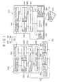
- Fig. 1 is an explanatory diagram showing the configuration of a preferred embodiment implementing a radio transmission apparatus provided by the present invention.
- the radio transmission apparatus 100 is explained by referring to Fig. 1 as follows.
- the radio transmission apparatus 100 shown in Fig. 1 comprises a signal transmitting and receiving apparatus 200 and a display apparatus 300.
- the signal transmitting and receiving apparatus 200 comprises components including a selector unit 205, a control unit 210, a transmission / reception switching unit 240 and an antenna 250.
- the selector unit 205 has a plurality of input terminals, which are connected to pieces of electronic equipment 281, 282 and 283 respectively.
- the pieces of electronic equipment 281, 282 and 283 are an audio tape recorder, an optical-disc drive and a digital CS tuner, which each supply a video signal VS and an audio signal AS to a selector unit 205.
- the video signal VS and the audio signal AS are also referred to as an AV (Audio Visual) signal.
- the selector unit 205 selects one of the pieces of electronic equipment 281, 282 and 283, passing on the AV signal received from the selected piece of electronic equipment to the control unit 210.
- the control unit 210 has a function to control the operations of the selector unit 205 and the transmission / reception switching unit 240 as well as a function to control the operations of the pieces of electronic equipment 281, 282 and 283 on the basis of a control signal CS to be described later.
- control unit 210 includes a signal processing unit 215, an RF transmission unit 220 and an RF reception unit 230.
- the signal processing unit 215 modulates the video signal VS and the audio signal AS received thereby to generate an RF signal converted into an appropriate amplitude. That is, the control unit 210 converts the video signal VS and the audio signal AS into RF signal, which can be transmitted as an electric wave.
- the RF transmission unit 220 comprises components including a modulator for modulating a carrier with the video signal VS and the audio signal AS, a frequency changer as well as a local oscillator, which are used for carrying out frequency conversion to generate a high-frequency signal, a PLL circuit, a transmission filter and a power amplifier.
- the RF transmission unit 220 has a function to modulate an RF signal received from the signal processing unit 215, amplify the modulated signal and output the amplified signal.
- the RF reception unit 230 comprises components including a low-noise amplifier, a reception filter, a frequency converter, a local oscillator and a PLL circuit.
- the RF reception unit 230 has a function to demodulate a control signal CS received from the antenna 250.
- the transmission / reception switching unit 240 supplies the RF signal received from the RF transmission unit 220 to the antenna 250 and supplies the control signal CS received from the antenna 250 to the RF reception unit 230.
- the antenna 250 has functions to transmit the modulated RF signal as an electric wave and receive the control signal CS coming as an electric wave.
- the selector unit 205 selects one of the pieces of electronic equipment 281, 282 and 283, passing on a video signal VS and an audio signal AS received from the selected piece of electronic equipment to the signal processing unit 215 by way of the selector unit 205, which converts the video signal VS and the audio signal AS into an RF signal. Then, the RF transmission unit 220 converts the RF signal into a high-frequency signal, which is supplied to the antenna 250 by way of the transmission / reception switching unit 240.
- the antenna 250 receives a control signal CS arriving as an electric wave and supplies the control signal CS to the RF reception unit 230 by way of the transmission / reception switching unit 240.
- the control signal CS is supplied to the signal processing unit 215.
- the control unit 210 controls the operations of the pieces of electronic equipment 281, 282 and 283 in accordance with the control signal CS.
- the signal transmitting and receiving apparatus 200 shown in Fig. 1 also receives a control signal CS and controls the operations of the pieces of electronic equipment 281, 282 and 283 in accordance with the control signal CS. In this way, the pieces of electronic equipment 281, 282 and 283 are controlled remotely and in a centralized manner.
- the display apparatus 300 shown in Fig. 1 comprises components including an antenna 310, a transmission / reception switching unit 320, a control unit 325, a display unit 360 and an audio output unit 370.
- the antenna 310 has a function to receive a video signal VS and an audio signal AS which are an RF signal transmitted as an electric wave.
- the antenna 310 also has a function to transmit a control signal CS.
- the transmission / reception switching unit 320 switches the display apparatus 300 from a reception mode to a transmission mode and vice versa.
- the antenna 310 receives a video signal VS and an audio signal AS.
- the antenna 310 transmits a control signal CS.
- control unit 325 comprises components including an RF transmission unit 340, an RF reception unit 330 and a signal processing unit 350.
- the RF reception unit 330 comprises components including a low-noise filter, a reception filter, a frequency converter, a local oscillator and a PLL circuit.
- the RF reception unit 330 has a function to demodulate a video signal VS and an audio signal AS received by the antenna 310.
- the RF transmission unit 340 comprises components including a modulator for modulating a carrier with the control signal CS, a frequency changer as well as a local oscillator, which are used for carrying out frequency conversion to generate a high-frequency signal, a PLL circuit, a transmission filter and a power amplifier.
- the RF transmission unit 340 has a function to modulate the CS signal received from the signal processing unit 350, amplify the modulated signal and output the amplified signal.
- the signal processing unit 350 has functions to filter the video signal VS and the audio signal AS as well as to change their formats, and output the filtered and reformatted signals to the display unit 360.
- the signal processing unit 350 also receives the control signal CS transmitted by a remote control unit 400 by way of an optical receiver 355, which serves as a control-signal reception unit for receiving the control signal CS.
- the signal processing unit 350 also has a function to modulate the received control signal CS and converts the modulated control signal CS into an RF signal having a proper amplitude.
- control unit 325 has a function to convert the control signal CS into an RF signal that can be transmitted as an electric wave.
- the control unit 325 also has a function to convert the video signal VS and the audio signal AS, which are received as an RF signal, into signals recognizable by the display unit 360 and the audio output unit 370 respectively.
- the display unit 360 has a function to output an image based on the video signal VS.
- the audio output unit 370 is typically a speaker provided inside or outside the display apparatus 300 for outputting a sound based on the audio signal AS.
- the antenna 310 receives a video signal VS and an audio signal AS, which are transmitted as an electric wave of an RF signal, and supplies the video signal VS and the audio signal AS to the RF reception unit 330 by way of the transmission / reception switching unit 320.
- the RF signal is then demodulated into a video signal VS and an audio signal AS before being supplied to the signal processing unit 350.
- the signal processing unit 350 changes the formats of the video signal VS and the audio signal AS to predetermined formats before supplying the video signal VS to the display unit 360 and the audio signal AS to the audio output unit 370.
- the display unit 360 outputs an image based on the video signal VS and the audio output unit 370 outputs a sound based on the audio signal AS.
- the frequency changing unit 400 transmits a control signal CS to the control-signal reception unit 355.
- the control signal CS is then converted into an RF signal in the signal processing unit 350 and the RF transmission unit 340.
- the control signal CS converted into the RF signal is supplied to the antenna 310 by way of the transmission / reception switching unit 320.
- the antenna 310 transmits the RF signal to the outside world as an electric wave.
- a control signal CS including control information for the pieces of electronic equipment 281, 282 and 283 is received by the display apparatus 300 and then transmitted by the antenna 310, making the pieces of electronic equipment 281, 282 and 283 easy to operate. That is, the user needs merely to operate the frequency changing unit 400 to transmit the control signal to the display apparatus 300 only. In this way, it is possible to control the display apparatus 300 and the pieces of electronic equipment 281, 282 and 283 in a centralized manner, allowing the user interface to be improved.
- the signal transmitting and receiving apparatus 200 transmits a video signal VS and an audio signal AS as an electric wave to the display apparatus 300.
- the display apparatus 300 transmits a control signal CS to the signal transmitting and receiving apparatus 200 as an electric wave.
- the signal transmitting and receiving apparatus 200 controls the operations of the pieces of electronic equipment 281, 282 and 283 on the basis of the received control signal CS to adjust the video signal VS and the audio signal AS which is transmitted to the display apparatus 300.
- the display apparatus 300 outputs an image and a sound based on the received video signal VS and the received audio signal AS respectively.
- a video signal VS and an audio signal AS are transmitted from the signal transmitting and receiving apparatus 200 to the display apparatus 300 while a control signal CS is transmitted from the display apparatus 300 to the signal transmitting and receiving apparatus 200.
- the user interface can be improved.
- the pieces of electronic equipment 281, 282 and 283 connected to the signal transmitting and receiving apparatus 200 are placed at locations separated from a room in which the display apparatus 300 is located. In this case, the pieces of electronic equipment 281, 282 and 283 cannot probably be operated directly by using the frequency changing unit 400.
- the user is capable of operating the pieces of electronic equipment 281, 282 and 283 through operations of the frequency changing unit 400 by orienting the frequency changing unit 400 toward the display apparatus 300.
- the types of the pieces of equipment 281, 282 to 283 connected to the signal transmitting and receiving apparatus 200 can be displayed on the display apparatus 300.
- control and operations of the pieces of equipment 281, 282 to 283 can be managed in a centralized manner by using typically a menu screen of the display apparatus 300.
- the user interface can be improved.
- the selector unit 205 is incorporated in the signal transmitting and receiving apparatus 200 whereas a function to receive an AV signal is provided in the display apparatus 300. Therefore, the number of cords is small and wiring is well organized. Moreover, since the function to receive an AV signal is embedded in a wall-mounted television or an LCD television, there is no problem of a lack of installation space and the scene looks good.
- Embodiments of the present invention are not limited to the embodiment described above.
- an audio tape recorder an optical-disc drive and a digital CS tuner are cited as examples of the pieces of electronic equipment 281,282 and 283 shown in Fig. 1, it is possible to use any electronic equipment outputting a video signal and an audio signal such as an apparatus for developing software like the so-called MPEG data and an electronic computer.
Applications Claiming Priority (2)
| Application Number | Priority Date | Filing Date | Title |
|---|---|---|---|
| JP25478799 | 1999-09-08 | ||
| JP25478799A JP2001078168A (ja) | 1999-09-08 | 1999-09-08 | 表示装置、信号送受信装置、無線伝送装置及び信号送受信方法 |
Publications (1)
| Publication Number | Publication Date |
|---|---|
| EP1083744A2 true EP1083744A2 (de) | 2001-03-14 |
Family
ID=17269888
Family Applications (1)
| Application Number | Title | Priority Date | Filing Date |
|---|---|---|---|
| EP00307648A Withdrawn EP1083744A2 (de) | 1999-09-08 | 2000-09-05 | Anzeigevorrichtung, Signalsender/Empfängergerät und Funkübertragungsgerät |
Country Status (5)
| Country | Link |
|---|---|
| US (1) | US6798459B1 (de) |
| EP (1) | EP1083744A2 (de) |
| JP (1) | JP2001078168A (de) |
| KR (1) | KR100730839B1 (de) |
| CN (1) | CN1287342A (de) |
Cited By (4)
| Publication number | Priority date | Publication date | Assignee | Title |
|---|---|---|---|---|
| US7024164B2 (en) * | 2000-08-21 | 2006-04-04 | Sony Corporation | Radio communication apparatus |
| DE102004055884A1 (de) * | 2004-11-19 | 2006-05-24 | Audi Ag | Leuchteinrichtung für ein Kraftfahrzeug umfassend eine oder mehrere LED's |
| US7512087B2 (en) | 2000-10-04 | 2009-03-31 | Sony Corporation | Communication system, apparatus and methods employing multiple communication networks |
| EP2191641A1 (de) * | 2007-07-23 | 2010-06-02 | Lg Electronics Inc. | Fernbedienung und system und verfahren zur fernbedienung eines digitalfernsehers |
Families Citing this family (14)
| Publication number | Priority date | Publication date | Assignee | Title |
|---|---|---|---|---|
| KR100453041B1 (ko) * | 2002-02-08 | 2004-10-15 | 삼성전자주식회사 | 영상 신호 송신 장치, 수신 장치, 이에 적합한 송수신기,그리고 채널 결정 방법 |
| US6975364B2 (en) * | 2002-06-13 | 2005-12-13 | Hui-Lin Lin | Radio television and frequency modulation monitor transmitting receiving control apparatus |
| JP3957717B2 (ja) * | 2003-04-30 | 2007-08-15 | 富士通株式会社 | 情報処理システム、情報処理装置、表示装置、及び情報処理システムにおけるチャンネル設定方法 |
| US7792970B2 (en) | 2005-06-17 | 2010-09-07 | Fotonation Vision Limited | Method for establishing a paired connection between media devices |
| US7685341B2 (en) * | 2005-05-06 | 2010-03-23 | Fotonation Vision Limited | Remote control apparatus for consumer electronic appliances |
| US8232930B2 (en) | 2004-02-13 | 2012-07-31 | Sharp Kabushiki Kaisha | Display apparatus, wireless transmitting and receiving system, display method, display control program, and recording medium |
| US7584494B2 (en) * | 2004-06-28 | 2009-09-01 | Dow Iii Leo F | Cable to wireless conversion system for in-home video distribution |
| US7694048B2 (en) * | 2005-05-06 | 2010-04-06 | Fotonation Vision Limited | Remote control apparatus for printer appliances |
| JP4873978B2 (ja) * | 2006-03-31 | 2012-02-08 | パナソニック株式会社 | 映像供給装置、映像表示装置、およびこれらで構成された映像表示システム |
| US20090115915A1 (en) * | 2006-08-09 | 2009-05-07 | Fotonation Vision Limited | Camera Based Feedback Loop Calibration of a Projection Device |
| US8482390B2 (en) | 2006-11-03 | 2013-07-09 | Nokia Corporation | Remote control of apparatus with media player |
| US20100245667A1 (en) * | 2009-03-24 | 2010-09-30 | Sony Corporation | Non-standalone tv pc |
| KR102059132B1 (ko) * | 2013-05-21 | 2019-12-24 | 삼성전자주식회사 | 근거리 무선 통신이 가능한 디스플레이 장치 및 디스플레이 장치를 생산하는 방법 |
| CN109166578B (zh) * | 2018-08-14 | 2021-05-11 | Oppo广东移动通信有限公司 | 移动终端、语音控制方法及相关产品 |
Family Cites Families (14)
| Publication number | Priority date | Publication date | Assignee | Title |
|---|---|---|---|---|
| JPH03266566A (ja) * | 1990-03-15 | 1991-11-27 | Alps Electric Co Ltd | カメラの無線操縦装置および電動機器の2方向同時制御装置 |
| US5475835A (en) * | 1993-03-02 | 1995-12-12 | Research Design & Marketing Inc. | Audio-visual inventory and play-back control system |
| US5995155A (en) * | 1995-07-17 | 1999-11-30 | Gateway 2000, Inc. | Database navigation system for a home entertainment system |
| US5774063A (en) * | 1995-12-14 | 1998-06-30 | International Business Machines Corporation | Method and apparatus for software based wireless remote control of electronic devices |
| US5719622A (en) * | 1996-02-23 | 1998-02-17 | The Regents Of The University Of Michigan | Visual control selection of remote mechanisms |
| DE19629484A1 (de) * | 1996-07-12 | 1998-01-15 | Arnold & Richter Kg | Vorrichtung zur Steuerung, Regelung und Kontrolle einer Laufbildkamera |
| JP2970559B2 (ja) * | 1996-11-13 | 1999-11-02 | 日本電気株式会社 | セルラの使用制限信号送受信装置 |
| US6282714B1 (en) * | 1997-01-31 | 2001-08-28 | Sharewave, Inc. | Digital wireless home computer system |
| US6008777A (en) | 1997-03-07 | 1999-12-28 | Intel Corporation | Wireless connectivity between a personal computer and a television |
| KR100232499B1 (ko) * | 1997-05-23 | 1999-12-01 | 김동식 | 자동 인지 기능을 가진 양방향 원격제어 송수신 장치 |
| US6577326B1 (en) * | 1997-08-29 | 2003-06-10 | Koninklijke Philips Electronics N.V. | Computer-controlled home theater independent user-control |
| US5982363A (en) * | 1997-10-24 | 1999-11-09 | General Instrument Corporation | Personal computer-based set-top converter for television services |
| US6034722A (en) * | 1997-11-03 | 2000-03-07 | Trimble Navigation Limited | Remote control and viewing for a total station |
| US6385772B1 (en) * | 1998-04-30 | 2002-05-07 | Texas Instruments Incorporated | Monitoring system having wireless remote viewing and control |
-
1999
- 1999-09-08 JP JP25478799A patent/JP2001078168A/ja not_active Ceased
-
2000
- 2000-09-01 US US09/653,631 patent/US6798459B1/en not_active Expired - Fee Related
- 2000-09-04 KR KR1020000051936A patent/KR100730839B1/ko not_active IP Right Cessation
- 2000-09-05 EP EP00307648A patent/EP1083744A2/de not_active Withdrawn
- 2000-09-08 CN CN00133122A patent/CN1287342A/zh active Pending
Cited By (6)
| Publication number | Priority date | Publication date | Assignee | Title |
|---|---|---|---|---|
| US7024164B2 (en) * | 2000-08-21 | 2006-04-04 | Sony Corporation | Radio communication apparatus |
| US7512087B2 (en) | 2000-10-04 | 2009-03-31 | Sony Corporation | Communication system, apparatus and methods employing multiple communication networks |
| DE102004055884A1 (de) * | 2004-11-19 | 2006-05-24 | Audi Ag | Leuchteinrichtung für ein Kraftfahrzeug umfassend eine oder mehrere LED's |
| EP2191641A1 (de) * | 2007-07-23 | 2010-06-02 | Lg Electronics Inc. | Fernbedienung und system und verfahren zur fernbedienung eines digitalfernsehers |
| EP2191641A4 (de) * | 2007-07-23 | 2013-01-23 | Lg Electronics Inc | Fernbedienung und system und verfahren zur fernbedienung eines digitalfernsehers |
| US8687130B2 (en) | 2007-07-23 | 2014-04-01 | Lg Electronics Inc. | Remote controller, and system and method for remotely controlling digital television |
Also Published As
| Publication number | Publication date |
|---|---|
| CN1287342A (zh) | 2001-03-14 |
| JP2001078168A (ja) | 2001-03-23 |
| US6798459B1 (en) | 2004-09-28 |
| KR100730839B1 (ko) | 2007-06-20 |
| KR20010030250A (ko) | 2001-04-16 |
Similar Documents
| Publication | Publication Date | Title |
|---|---|---|
| US6798459B1 (en) | Apparatus and method for transmitting and receiving, as an electric wave, a signal generated by electronic equipment, and a control signal to control operation of the electronic equipment | |
| US6131130A (en) | System for convergence of a personal computer with wireless audio/video devices wherein the audio/video devices are remotely controlled by a wireless peripheral | |
| KR100490435B1 (ko) | 양 방향으로 명령어를 공유하는 무선 세탑박스 시스템 및그 방법 | |
| JPWO2010146806A1 (ja) | リモートコントロールシステム、テレビジョン受信機およびペアリング方法 | |
| JP2000083178A5 (ja) | 画像表示システム及びリモートコントロールシステム | |
| CN101729818B (zh) | 显示设备和无线电传输控制方法 | |
| US20140044277A1 (en) | Wireless audio transmission system, receiver, video camera and audio mixer | |
| US6040874A (en) | Peripheral unit connection status display device of composite video apparatus and methods thereof | |
| JPH1079896A (ja) | テレビ受像機 | |
| US20120263477A1 (en) | Portable Terminal and Method for Remote Control of Electronic Products | |
| JPH11284757A (ja) | 携帯電話リモコンシステム | |
| JPH10210570A (ja) | リモコン送信機およびそれを用いた情報転送システム | |
| KR100433240B1 (ko) | 무선으로 양방향 조절이 가능한 셋탑 시스템 | |
| US20030214604A1 (en) | Display system and method of controlling the same | |
| KR100531301B1 (ko) | 다기능 원격 제어장치 | |
| JP3137819B2 (ja) | テレビ信号処理装置及びテレビ信号処理システム | |
| KR100341527B1 (ko) | 무선주파수합성수신기를프로그램하기위한다운로딩방법및장치 | |
| JP2002158935A (ja) | テレビワイヤレス伝送システム | |
| JP2006114941A (ja) | Am放送波受信機能を備えたオーディオ機器 | |
| KR200176784Y1 (ko) | 전화선을 이용한 텔레비젼과 컴퓨터 연결 장치 | |
| JP2005347858A (ja) | 通信システムおよび通信端末 | |
| KR100336615B1 (ko) | 원격제어장치 | |
| KR200289678Y1 (ko) | 무선 디스플레이 장치 | |
| JPH07131768A (ja) | テレビ受像機 | |
| KR20050027560A (ko) | 메뉴간 바로가기 기능이 지원되는 디지털 영상장치 및 그변환 방법 |
Legal Events
| Date | Code | Title | Description |
|---|---|---|---|
| PUAI | Public reference made under article 153(3) epc to a published international application that has entered the european phase |
Free format text: ORIGINAL CODE: 0009012 |
|
| AK | Designated contracting states |
Kind code of ref document: A2 Designated state(s): AT BE CH CY DE DK ES FI FR GB GR IE IT LI LU MC NL PT SE |
|
| AX | Request for extension of the european patent |
Free format text: AL;LT;LV;MK;RO;SI |
|
| STAA | Information on the status of an ep patent application or granted ep patent |
Free format text: STATUS: THE APPLICATION HAS BEEN WITHDRAWN |
|
| 18W | Application withdrawn |
Withdrawal date: 20020924 |