EP1083579B1 - Überspannungsableiter - Google Patents
Überspannungsableiter Download PDFInfo
- Publication number
- EP1083579B1 EP1083579B1 EP00810723A EP00810723A EP1083579B1 EP 1083579 B1 EP1083579 B1 EP 1083579B1 EP 00810723 A EP00810723 A EP 00810723A EP 00810723 A EP00810723 A EP 00810723A EP 1083579 B1 EP1083579 B1 EP 1083579B1
- Authority
- EP
- European Patent Office
- Prior art keywords
- housing
- surge arrester
- active part
- connection
- bottle
- Prior art date
- Legal status (The legal status is an assumption and is not a legal conclusion. Google has not performed a legal analysis and makes no representation as to the accuracy of the status listed.)
- Expired - Lifetime
Links
Images
Classifications
-
- H—ELECTRICITY
- H01—ELECTRIC ELEMENTS
- H01C—RESISTORS
- H01C7/00—Non-adjustable resistors formed as one or more layers or coatings; Non-adjustable resistors made from powdered conducting material or powdered semi-conducting material with or without insulating material
- H01C7/10—Non-adjustable resistors formed as one or more layers or coatings; Non-adjustable resistors made from powdered conducting material or powdered semi-conducting material with or without insulating material voltage responsive, i.e. varistors
- H01C7/12—Overvoltage protection resistors; Arresters
Definitions
- a surge arrester with a cylindrically symmetrical, groundable housing, through which a plug connection can be brought to high voltage potential, and with an arranged in the housing and aligned along the axis of symmetry active part with two connection fittings, at least one disposed between the two connection fittings varistor element and a tensioning device which acts on the connection fittings and the at least one varistor element with the formation of contact force, in which the active part is surrounded by an elastic insulating material sleeve which ensures insulation of the housing.
- An arrester of the aforementioned type is offered commercially by numerous manufacturers and serves to protect metal-encapsulated, gas-insulated switchgear.
- the arrester is in this case connected to an outer or inner cone having, high voltage leading plug contact of the system and then limits surges that are generated by switching operations or by reflection of traveling waves.
- the arrester contains a grounded and touch-proof housing and a built-in the housing and made of varistor elements, in particular based on metal oxide, spark-free constructed active part.
- the active part is cast in an insulating body of silicone rubber, the outer surface rests at least partially on the inner surface of the housing.
- such an arrester For controlling the electric field between the active part located at high voltage potential and the grounded housing, such an arrester generally comprises semiconductive or conductive field control elements.
- EP 0 810 613 A2 describes a surge arrester with an active part embedded in a cast housing made of insulating material. Two connection fittings and varistor elements of the active part are clamped together to form contact force by means of a loop of insulating material.
- a surge arrester is described with a arranged between two terminal fittings and the Varistoriano beaufschalierenden to form contact force clamping device, wherein the clamping device has at least one with its end mounted on the two connection fittings loop.
- the invention has for its object to provide a surge arrester of the type mentioned, which is characterized by good mechanical and electrical properties and which can be produced at the same time in a cost effective manner.
- the active part is held together by at least one mounted on its two connection fittings loop and acted upon by contact force.
- a housing surrounding the active part is bottle-shaped and has this housing a shaped like a bottleneck housing portion in which a connected to one of the two connection fittings and electrically conductively connected to the plug-in connection, cylindrically symmetrical trained conductor is performed.
- the surge arrester is characterized by excellent long-term stability due to the mechanically very stable active part and the lack of field-controlling elements.
- a particularly homogeneous distribution of the electric field and thus a particularly advantageous dielectric behavior of the surge arrester is achieved if a conically widening housing section adjoins the bottle neck-shaped housing section, in which an end of the current conductor connected to the plug connection is connected to one of the two connection fittings ,
- fastening elements are advantageously a mounting flange guided on the bottle-shaped housing section and a compression spring arranged between the fastening flange and the widening.
- the bottle-shaped housing is generally pressure-resistant and provided with a pressure relief valve.
- This pressure relief valve can advantageously be arranged on the housing bottom or be provided with a predetermined breaking point floor itself. In response to the pressure relief valve emerging from the bottle-shaped housing hot gases can then easily - and without damaging the connector - be removed.
- connection fitting 1 has two preferably made of aluminum and spaced apart along an axis z connecting fittings 1, 2.
- the connection fitting 1 is connected via a cylindrically symmetrical formed and along the axis z guided conductor 3 with an outer cone 4 ( Figure 1) and an inner cone 4 '( Figure 2) having plug connection 5.
- This plug-in connection can be connected to a high-voltage-carrying plug-in connection of a metal-encapsulated, gas-insulated system which has an inner or outer cone.
- the connection fitting 2 can be guided to earth potential via a likewise electrically guided current conductor 6.
- a loop 7 made of glass-fiber-reinforced and embedded in a plastic matrix band is mounted with its two ends in recesses or in formations of the connection fittings 1, 2.
- Cylindrical varistor elements 9 of non-linear resistance material are arranged between the connection fittings 1, 2, forming a columnar active active part 8 aligned along the axis z.
- a columnar varistor element may also be provided.
- non-designated springy current transfer elements are arranged in the figures.
- the two connection fittings 1, 2 and the intermediate parts are subjected to a defined clamping force. In this way, a good contacting of the varistor elements 9 provided in the active part with each other and with the connection fittings 1, 2 is achieved.
- the clamping force is absorbed by the loop 7. Instead of a loop, two or possibly more loops for tensioning the active part 8 can be used.
- the active part 8 is arranged in a cylindrically symmetrical, groundable housing 10.
- This housing 10 may be made of metal, such as aluminum, of an electrically conductive polymeric material, such as a polyethylene filled with conductive carbon black, or of a polymeric material, such as polyethylene, provided with an electrically conductive jacket.
- the housing 10 has a bottom 11 through which the current conductor 6, which can be connected to ground potential via a screw connection 12, is guided.
- the bottom 11 is formed so that it gives in the presence of an overpressure of a certain size in the interior of the housing 10 and the interior of the housing relieved of the pressure.
- the active part is surrounded by an insulation to groundable wall of the housing 10 ensuring insulating material 13.
- material for the shell are preferably elastic insulating materials, such as preferably silicones, into consideration. In the manufacture of the surge arrester, this material can first be poured in liquid state into the housing 10 which already accommodates the preassembled active part 8 and the current conductors 3 and 6 and then polymerized in the housing 10 to form the preferably elastic sheath 13. Dielectric undesirable gaps or pores in the field moderately high loaded area between the Ableiterdonteil 8 and the insulating material 13 are avoided by a coating of the active part 8 with a bonding agent. Nevertheless, occurring in the housing interior between the active part 8 and the wall of the housing 10 pores and / or gaps can be filled to improve the dielectric strength with a gel-like insulating agent, such as a silicone oil, preferably under vacuum.
- a gel-like insulating agent such as a silicone oil
- the housing 10 is bottle-shaped and has a housing portion 14 formed in the manner of a bottle neck, which is arranged symmetrically to the axis z and thus also to the current conductor 3.
- a housing portion 14 formed in the manner of a bottle neck, which is arranged symmetrically to the axis z and thus also to the current conductor 3.
- To the bottle neck-shaped housing portion 14 includes a conically widening housing portion 15, in which a connected to the terminal fitting 1 end of the plug-in terminal 5 connected to the current conductor 3 is guided.
- the bottle-neck-shaped housing section 14 is crimped on its end facing the plug connection 5 to form an expansion 16.
- the bottle-neck-shaped housing section 14 carries a fastening flange 17 and a compression spring 18 guided between fastening flange 17 and widening 16.
- connection 5 is plugged into a connection provided with an inner cone of a metal-enclosed switchgear.
- the surge arrester is electrically connected to the switchgear.
- the mounting flange 17 is firmly connected under tension of the compression spring 18 with the encapsulation of the switchgear.
- the surge arrester is then set in elastically slightly springy manner on the metal enclosure of the switchgear.
- a provided between the plug connection 5 and widening 16 and arranged outside the housing 10 section 19 of the insulating material 13 provides the insulation between the high-voltage current conductor 3 and the metal enclosure of the switchgear and the housing 10 and the mounting flange 17 ago.
Landscapes
- Engineering & Computer Science (AREA)
- Microelectronics & Electronic Packaging (AREA)
- Physics & Mathematics (AREA)
- Electromagnetism (AREA)
- Thermistors And Varistors (AREA)
- Emergency Protection Circuit Devices (AREA)
- Measurement Of The Respiration, Hearing Ability, Form, And Blood Characteristics Of Living Organisms (AREA)
- Apparatuses And Processes For Manufacturing Resistors (AREA)
- Details Of Connecting Devices For Male And Female Coupling (AREA)
Description
- Bei der Erfindung wird ausgegangen von einem Überspannungsableiter mit einem zylindersymmetrisch ausgebildeten, erdbaren Gehäuse, durch welches ein auf Hochspannungspotential bringbarer Steckanschluss geführt ist, und mit einem im Gehäuse angeordneten und längs der Symmetrieachse ausgerichteten Aktivteil mit zwei Anschlussarmaturen, mindestens einem zwischen den beiden Anschlussarmaturen angeordneten Varistorelement und einer die Anschlussarmaturen und das mindestens eine Varistorelement unter Bildung von Kontaktkraft beaufschlagenden Spannvorrichtung, bei dem das Aktivteil von einer die Isolation zum Gehäuse sicherstellenden elastischen Isolierstoffhülle umgeben ist.
- Ein Ableiter der vorgenannten Art wird von zahlreichen Herstellern im Handel angeboten und dient dem Schutz metallgekapselter, gasisolierter Schaltanlagen. Der Ableiter wird hierbei mit einem einen Aussen- oder Innenkonus aufweisenden, hochspannungsführenden Steckkontakt der Anlage verbunden und begrenzt dann Überspannungen, die durch Schaltvorgänge oder durch Reflexion von Wanderwellen erzeugt werden. Der Ableiter enthält ein auf Erdpotential geführtes und berührungssicheres Gehäuse und ein in das Gehäuse eingebautes und aus Varistorelementen, insbesondere auf der Basis von Metalloxid, funkenstreckenlos aufgebautes Aktivteil. Das Aktivteil ist in einen Isolierkörper aus Silikonkautschuk eingegossen, dessen Aussenfläche zumindest teilweise auf der Innenfläche des Gehäuses aufliegt. Zur Steuerung des elektrischen Feldes zwischen dem auf Hochspannungspotential befindlichen Aktivteil und dem auf Erdpotential geführten Gehäuse weist ein solcher Ableiter im allgemeinen halbleitende oder leitende Feldsteuerelemente auf.
- In EP 0 810 613 A2 ist ein Überspannungsableiter beschrieben mit einem in ein Gussgehäuse aus Isoliermaterial eingebetteten Aktivteil. Zwei Anschlussarmaturen und Varistorelemente des Aktivteils sind unter Bildung von Kontaktkraft mittels einer Schlaufe aus Isoliermaterial miteinander verspannt. In der US 5517382 ist ein Überspannungsableiter beschrieben mit einer zwischen zwei Anschlussarmaturen angeordneten und der Varistorelemente unter Bildung von Kontaktkraft beaufschalgenden Spann vorrichtung, wobei die Spannvorrichtung mindestens eine mit ihren Ende auf den beiden Anschlussarmaturen gelagerte Schlaufe aufweist.
- Der Erfindung, wie sie in Patentanspruch 1 angegeben ist, liegt die Aufgabe zugrunde, einen Überspannungsableiter der eingangs genannten Art zu schaffen, welcher sich durch gute mechanische und elektrische Eigenschaften auszeichnet und welcher sich zugleich in kostengünstiger Weise herstellen lässt.
- Beim Überspannungsableiter nach der Erfindung ist das Aktivteil durch mindestens eine auf seinen beiden Anschlussarmaturen gelagerte Schlaufe zusammengehalten und mit Kontaktkraft beaufschlagt. Hierdurch wird in herstellungtechnisch einfacher und daher kostengünstiger Weise eine hohe mechanische Festigkeit des Aktivteils erreicht. Zugleich ist ein das Aktivteil umgebendes Gehäuse flaschenförmig ausgeführt und weist dieses Gehäuse einen nach Art eines Flaschenhalses geformten Gehäuseabschnitt auf, in dem ein an eine der beiden Anschlussarmaturen angeschlossener und mit dem Steckanschluss elektrisch leitend verbundener, zylindersymmetrisch ausgebildeter Stromleiter geführt ist. Hierdurch wird eine Ausbildung des elektrischen Feldes im Gehäuseinneren erreicht, welche auch bei nichtzylindersymmetrischer Beschaffenheit des Aktivteils infolge der Halteschlaufe feldsteuemde halbleitende oder leitende Elemente und Beschichtungen zwischen dem Aktivteil und der Gehäusewand entbehrlich macht. Zugleich zeichnet sich der Überspannungsableiter wegen des mechanisch sehr beständigen Aktivteils und wegen der fehlenden feldsteuernden Elemente durch eine hervorragende Langzeitstabilität aus.
- Eine besonders homogene Verteilung des elektrischen Feldes und damit ein besonders vorteilhaftes dielektrisches Verhalten des Überspannungsableiters wird erreicht, wenn an den flaschenhalsförmig ausgebildeten Gehäuseabschnitt ein sich konisch erweiternder Gehäuseabschnitt anschliesst, in dem ein an eine der beiden Anschlussarmaturen angeschlossenes Ende des mit dem Steckanschluss verbundenen Stromleiters geführt ist.
- Es ist günstig, den flaschenhalsförmig ausgebildeten Gehäuseabschnitt an seinem dem Steckanschluss zugewandten Ende aufzuweiten, da die Aufweitung dann als Anschlag für Befestigungselemente dient, die auf diesem Gehäuseabschnitt geführt werden. Solche Befestigungselemente sind mit Vorteil ein am flaschenförmig ausgebildeten Gehäuseabschnitt geführter Befestigungsflansch und eine zwischen Befestigungsflansch und Aufweitung angeordnete Druckfeder.
- Da bei einer möglicherweise auftretenden Überlastung des Überspannungsableiters gegebenenfalls Überdrücke auftreten können, ist das flaschenförmige Gehäuse im allgemeinen druckfest ausgebildet und mit einem Überdruckventil versehen. Dieses Überdruckventil kann mit Vorteil am Gehäuseboden angeordnet oder der mit einer Sollbruchstelle versehene Boden selber sein. Beim Ansprechen des Überdruckventils aus dem flaschenförmigen Gehäuse austretende heisse Gase können dann problemlos - und ohne die Steckverbindung zu beschädigen - entfernt werden.
- Dielektrisch unerwünschte Spalte und/oder Poren zwischen dem Ableiteraktivteil und einer zwischen Aktivteil und Gehäuse vorgesehenen Isolierhülle werden durch eine Beschichtung des Aktivteils mit einem Haftvermittler vermieden. Dennoch im Gehäuseinneren zwischen Aktivteil und Gehäusewand auftretende Poren und/oder Spalte werden zur Verbesserung der dielektrischen Festigkeit mit einem gelartigen Isoliermittel aufgefüllt.
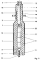
- Bevorzugte Ausführungsbeispiel der Erfindung und die damit erzielbaren weiteren Vorteile werden nachfolgend anhand von Zeichnungen näher erläutert. Hierbei zeigt:
- Fig.1
- eine Aufsicht auf einen längs einer Achse geführten Schnitt durch eine Ausführungsform des Überspannungsableiters nach der Erfindung mit einem als Aussenkonus ausgebildeten Steckanschluss, und
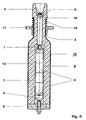
- Fig.2
- eine Aufsicht auf einen längs einer Achse geführten Schnitt durch eine Ausführungsform des Überspannungsableiters nach der Erfindung mit einem als Innenkonus ausgebildeten Steckanschluss.
- In den beiden Figuren bezeichnen gleiche Bezugszeichen auch gleichwirkende Teile. Die in den Figuren 1 und 2 dargestellten Überspannungsableiter weisen zwei vorzugsweise aus Aluminium bestehende und voneinander längs einer Achse z beabstandete Anschlussarmaturen 1, 2 auf. Die Anschlussarmatur 1 ist über einen zylindersymmetrisch ausgebildeten und längs der Achse z geführten Stromleiter 3 mit einem einen Aussenkonus 4 (Fig.1) bzw. einen Innenkonus 4' (Fig.2) aufweisenden Steckanschluss 5 verbunden. Dieser Steckanschluss ist mit einem einen Innen- bzw. Aussenkonus aufweisenden, hochspannungsführenden Steckanschluss einer metallgekapselten, gasisolierten Anlage verbindbar. Die Anschlussarmatur 2 ist über einen ebenfalls axial geführten Stromleiter 6 auf Erdpotential führbar. Eine Schlaufe 7 aus glasfaserverstärktem und in eine Kunststoffmatrix eingebettetem Band ist mit ihren beiden Enden in Ausnehmungen oder in Anformungen der Anschlussarmaturen 1, 2 gelagert.
- Zwischen den Anschlussarmaturen 1, 2 sind unter Bildung eines säulenförmigen und längs der Achse z ausgerichteten Ableiteraktivteils 8 zylinderförmige Varistorelemente 9 aus nichtlinearem Widerstandsmaterial, etwa auf der Basis von Metalloxid, wie insbesondere von ZnO, angeordnet. Alternativ kann statt mehrerer Elemente 9 auch ein säulenförmig ausgebildetes Varistorelement vorgesehen sein. Zwischen den Anschlussarmaturen 1, 2 und den beiden benachbarten Varistorelementen 9 sowie zwischen den einzelnen Varistorelementen 9 sind in den Figuren nicht bezeichnete fedemde Stromübergangselemente angeordnet. Die beiden Anschlussarmaturen 1, 2 und die dazwischenliegenden Teile sind mit einer definierten Spannkraft beaufschlagt. Hierdurch wird eine gute Kontaktierung der im Aktivteil vorgesehenen Varistorelemente 9 untereinander und mit den Anschlussarmaturen 1, 2 erreicht. Die Spannkraft wird durch die Schlaufe 7 aufgenommen. Anstelle einer Schlaufe können zwei oder gegebenenfalls auch mehr Schlaufen zur Verspannung des Aktivteils 8 verwendet werden.
- Das Aktivteil 8 ist in einem zylindersymmetrisch ausgebildeten, erdbaren Gehäuse 10 angeordnet. Dieses Gehäuse 10 kann aus Metall, wie etwa Aluminium, aus einem elektrisch leitfähigen polymeren Material, beispielsweise einem mit Leitfähigkeitsruss gefüllten Polyäthylen, oder aus einem mit einem elektrisch leitfähigen Mantel versehenen polymeren Material, wie etwa Polyäthylen, bestehen.
- Das Gehäuse 10 weist einen Boden 11 auf, durch den der über einen Schraubanschluss 12 mit Erdpotential verbindbare Stromleiter 6 geführt ist. Der Boden 11 ist so ausgebildet, dass er beim Auftreten eines Überdrucks bestimmter Grösse im Inneren des Gehäuses 10 nachgibt und das Gehäuseinnere so vom Überdruck entlastet.
- Das Aktivteil ist von einer die Isolation zur erdbaren Wand des Gehäuses 10 sicherstellenden Isolierstoffhülle 13 umgeben. Als Material für die Hülle kommen vorzugsweise elastische Isolierstoffe, wie vorzugsweise Silikone, in Betracht. Dieses Material kann bei der Herstellung des Überspannungsableiters zunächst in flüssigem Zustand in das bereits das vormontierte Aktivteil 8 und die Stromleiter 3 und 6 aufnehmende Gehäuse 10 gegossen und danach unter Bildung der vorzugsweise elastischen Hülle 13 im Gehäuse 10 polymerisiert werden. Dielektrisch unerwünschte Spalte oder Poren im feldmässig hoch belasteten Bereich zwischen dem Ableiteraktivteil 8 und der Isolierstoffhülle 13 werden durch eine Beschichtung des Aktivteils 8 mit einem Haftvermittler vermieden. Dennoch im Gehäuseinneren zwischen dem Aktivteil 8 und der Wand des Gehäuses 10 auftretende Poren und/oder Spalte können zur Verbesserung der dielektrischen Festigkeit mit einem gelartigen Isoliermittel, etwa einem Silikonöl, vorzugsweise unter Vakuum aufgefüllt werden.
- Das Gehäuse 10 ist flaschenartig ausgebildet und weist einen nach Art eines Flaschenhalses ausgebildeten Gehäuseabschnitt 14 auf, welcher symmetrisch zur Achse z und damit auch zum Stromleiter 3 angeordnet ist. An den flaschenhalsförmig ausgebildeten Gehäuseabschnitt 14 schliesst ein sich konisch erweiternder Gehäuseabschnitt 15 an, in dem ein an die Anschlussarmatur 1 angeschlossenes Ende des mit dem Steckanschluss 5 verbundenen Stromleiters 3 geführt ist. Der flaschenhalsförmig ausgebildete Gehäuseabschnitt 14 ist an seinem dem Steckanschluss 5 zugewandten Ende unter Bildung einer Aufweitung 16 aufgebördelt. Ferner trägt der flaschenhalsförmig ausgebildete Gehäuseabschnitt 14 einen Befestigungflansch 17 und eine zwischen Befestigungsflansch 17 und Aufweitung 16 geführte Druckfeder 18.
- Durch die flaschenförmige Gestalt des Gehäuses 10 wird eine Ausbildung des elektrischen Feldes im Gehäuseinneren erreicht, welche auch bei nichtzylindersymmetrischer Beschaffenheit des Aktivteits 8 feldsteuemde, halbleitende und/oder leitende Elemente und/oder Beschichtungen zwischen dem Aktivteil 8 und der Gehäusewand entbehrlich macht.
- Zur Montage wird der Anschluss 5 in einen mit einem Innenkonus versehenen Anschluss einer metallgekapselten Schaltanlage gesteckt. Hierdurch ist der Überspannungsableiter elektrisch mit der Schaltanlage verbunden. Sodann wird der Befestigungsflansch 17 unter Spannen der Druckfeder 18 mit der Kapselung der Schaltanlage fest verbunden. Der Überspannungsableiter ist dann in elastisch geringfügig fedemder Weise auf der Metallkapselung der Schaltanlage festgesetzt.
- Ein zwischen Steckanschluss 5 und Aufweitung 16 vorgesehener und ausserhalb des Gehäuses 10 angeordneter Abschnitt 19 der Isolierstoffhülle 13 stellt die Isolation zwischen dem hochspannungsführenden Stromleiter 3 und der Metallkapselung der Schaltanlage bzw. dem Gehäuse 10 bzw. dem Befestigungsflansch 17 her.
-
- 1, 2
- Anschlussarmaturen
- 3
- Stromleiter
- 4
- Aussenkonus
- 5
- Steckanschluss
- 6
- Stromleiter
- 7
- Schlaufe
- 8
- Aktivteil
- 9
- Varistorelemente
- 10
- Gehäuse
- 11
- Gehäuseboden
- 12
- Schraubanschluss
- 13
- Isolierstoffhülle
- 14, 15
- Gehäuseabschnitte
- 16
- Aufweitung
- 17
- Befestigungsflansch
- 18
- Druckfeder
- 19
- Isolierstoffhüllenabschnitt
- z
- Achse
Claims (7)
- Überspannungsableiter mit einem zylindersymmetrisch ausgebildeten, erdbaren Gehäuse (10), durch welches ein auf Hochspannungspotential bringbarer Steckanschluss (5) geführt ist, und mit einem im Gehäuse (10) angeordneten und längs der Symmetrieachse (z) ausgerichteten Aktivteil (8) mit zwei Anschlussarmaturen (1, 2), mindestens einem zwischen den beiden Anschlussarmaturen angeordneten Varistorelement (9) und einer die Anschlussarmaturen (1, 2) und das mindestens eine Varistorelement (9) unter Bildung von Kontaktkraft beaufschlagenden Spannvorrichtung, bei dem das Aktivteil (8) von einer die Isolation zum Gehäuse (10) sicherstellenden Isolierstoffhülle (13) umgeben ist, dadurch gekennzeichnet, dass die Spannvorrichtung mindestens eine mit ihren Enden auf den beiden Anschlussarmaturen (1, 2) gelagerte Schlaufe (7) aufweist, und dass das Gehäuse (10) flaschenförmig ausgebildet ist und einen nach Art eines Flaschenhalses ausgebildeten Gehäuseabschnitt (14) aufweist, in dem ein an eine der beiden Anschlussarmaturen (1, 2) angeschlossener und mit dem Steckanschluss (5) elektrisch leitend verbundener, zylindersymmetrisch ausgebildeter Stromleiter (3) geführt ist.
- Überspannungsableiter nach Anspruch 1, dadurch gekennzeichnet, dass an den flaschenhalsförmig ausgebildeten Gehäuseabschnitt (14) ein sich konisch erweiternder Gehäuseabschnitt (15) anschliesst, in dem ein an eine (1) der beiden Anschlussarmaturen angeschlossenes Ende des mit dem Steckanschluss (5) verbundenen Stromleiters (3) geführt ist.
- Überspannungsableiter nach Anspruch 2, dadurch gekennzeichnet, dass der flaschenhalsförmig ausgebildete Gehäuseabschnitt (14) an seinem dem Steckanschluss (5) zugewandten Ende aufgeweitet ist.
- Überspannungsableiter nach Anspruch 3, dadurch gekennzeichnet, dass am flaschenförmig ausgebildeten Gehäuseabschnitt (14) ein Befestigungflansch (17) und eine zwischen Befestigungsflansch (17) und Aufweitung (16) angeordnete Druckfeder (18) geführt sind.
- Überspannungsableiter nach einem der Ansprüche 1 bis 4, dadurch gekennzeichnet, dass der Boden (11) des flaschenförmigen Gehäuses (10) überdruckempfindlich ausgebildet ist.
- Überspannungsableiter nach einem der Ansprüche 1 bis 5, dadurch gekennzeichnet, dass das Aktivteil (8) mit einem auf die lsolierstoffhülle (13) wirkenden Haftvermittler beschichtet ist.
- Überspannungsableiter nach einem der Ansprüche 1 bis 6, dadurch gekennzeichnet, dass vom Gehäuse (10) umschlossene, in der lsolierstoffhülle (13) oder zwischen der lsolierstoffhülle (13) und der Wand des Gehäuses (10) sowie dem Ableiteraktivteil (8) enthaltene Poren und/oder Spalte mit einem gelartigen lsoliermittel aufgefüllt sind.
Applications Claiming Priority (2)
| Application Number | Priority Date | Filing Date | Title |
|---|---|---|---|
| DE19942633 | 1999-09-07 | ||
| DE19942633A DE19942633A1 (de) | 1999-09-07 | 1999-09-07 | Überspannungsableiter |
Publications (3)
| Publication Number | Publication Date |
|---|---|
| EP1083579A2 EP1083579A2 (de) | 2001-03-14 |
| EP1083579A3 EP1083579A3 (de) | 2004-12-15 |
| EP1083579B1 true EP1083579B1 (de) | 2006-03-08 |
Family
ID=7921068
Family Applications (1)
| Application Number | Title | Priority Date | Filing Date |
|---|---|---|---|
| EP00810723A Expired - Lifetime EP1083579B1 (de) | 1999-09-07 | 2000-08-15 | Überspannungsableiter |
Country Status (9)
| Country | Link |
|---|---|
| US (1) | US6594133B1 (de) |
| EP (1) | EP1083579B1 (de) |
| JP (1) | JP4555447B2 (de) |
| AT (1) | ATE320072T1 (de) |
| BR (1) | BR0003990A (de) |
| DE (2) | DE19942633A1 (de) |
| HR (1) | HRP20000581A2 (de) |
| HU (1) | HUP0003510A3 (de) |
| PL (1) | PL342384A1 (de) |
Cited By (1)
| Publication number | Priority date | Publication date | Assignee | Title |
|---|---|---|---|---|
| EP2600358A1 (de) | 2011-12-02 | 2013-06-05 | ABB Technology AG | Überspannungsableiter |
Families Citing this family (14)
| Publication number | Priority date | Publication date | Assignee | Title |
|---|---|---|---|---|
| ES2237663T3 (es) * | 2002-07-15 | 2005-08-01 | Abb Schweiz Ag | Dispositivo electrico de conexion, en particular limitador de sobretension. |
| ATE442654T1 (de) * | 2003-02-12 | 2009-09-15 | Abb Technology Ag | Aktivteil für einen überspannungsableiter |
| EP1603141B1 (de) | 2004-06-04 | 2016-08-24 | ABB Schweiz AG | Gasisolierter Überspannungsableiter |
| EP1603140A1 (de) | 2004-06-04 | 2005-12-07 | ABB Technology AG | Aktivteil für einen gekapselten Überspannungsableiter |
| GB0417596D0 (en) * | 2004-08-06 | 2004-09-08 | Tyco Electronics Raychem Gmbh | High voltage connector arrangement |
| WO2007013724A1 (en) * | 2005-07-29 | 2007-02-01 | Electronics And Telecommunications Research Institute | Abrupt metal-insulator transition device, circuit for removing high-voltage noise using the abrupt metal-insulator transition device, and electrical and/or electronic system comprising the circuit |
| JP4550750B2 (ja) * | 2006-03-08 | 2010-09-22 | 株式会社日本Aeパワーシステムズ | アレスタ |
| DE102007027411A1 (de) * | 2007-06-11 | 2008-12-18 | Siemens Ag | Überspannungsableiteranordnung |
| EP2819250B1 (de) | 2013-06-26 | 2022-07-27 | 3M Innovative Properties Company | Kabelanordnung und verfahren zum verbinden eines stromkabels an eine elektrische anlage eines stromnetzes |
| DE202016100268U1 (de) * | 2016-01-21 | 2016-02-25 | Abb Technology Ag | Vorrichtung zur Erzeugung, Übertragung, Verteilung und/oder Verwendung elektrischer Energie oder eine Komponente einer solchen Vorrichtung sowie Gasdichtung für eine solche Vorrichtung oder Komponente |
| WO2020057915A1 (de) * | 2018-09-17 | 2020-03-26 | Siemens Aktiengesellschaft | Überspannungsableiter mit einer druckentlastungsvorrichtung und herstellungsverfahren für einen überspannungsableiter |
| CN110932096B (zh) * | 2019-12-26 | 2025-05-02 | 辽宁华隆电力科技股份有限公司 | 一种立体卷铁芯变压器用自断电式间隙避雷器 |
| CN211830199U (zh) * | 2020-01-22 | 2020-10-30 | 伊顿智能动力有限公司 | 隔爆型浪涌保护器 |
| CN114898956B (zh) * | 2022-05-26 | 2022-12-02 | 国网安徽省电力有限公司青阳县供电公司 | 一种基于智慧台区的配电网供电线路用避雷器 |
Family Cites Families (11)
| Publication number | Priority date | Publication date | Assignee | Title |
|---|---|---|---|---|
| US4029380A (en) * | 1967-08-15 | 1977-06-14 | Joslyn Mfg. And Supply Co. | Grounded surface distribution apparatus |
| JPS5769683A (en) * | 1980-10-20 | 1982-04-28 | Tokyo Shibaura Electric Co | Arrester |
| JPS6126286U (ja) * | 1984-07-23 | 1986-02-17 | 株式会社東芝 | 避雷器 |
| JPS6280988A (ja) * | 1985-10-02 | 1987-04-14 | 三菱電機株式会社 | 避雷器の抵抗分もれ電流測定装置 |
| US5088001A (en) * | 1990-02-23 | 1992-02-11 | Amerace Corporation | Surge arrester with rigid insulating housing |
| DE4306691A1 (de) * | 1993-03-04 | 1994-11-03 | Abb Management Ag | Ueberspannungsableiter |
| JP3279439B2 (ja) * | 1994-07-11 | 2002-04-30 | 株式会社日立製作所 | 機器内蔵形避雷器 |
| DE19504532A1 (de) * | 1995-02-11 | 1996-08-14 | Abb Management Ag | Verfahren zur Herstellung eines Isolators |
| US5625523A (en) * | 1995-04-03 | 1997-04-29 | Nedriga; Walter N. | Surge arrester |
| DE19622140A1 (de) * | 1996-06-01 | 1997-12-04 | Asea Brown Boveri | Überspannungsableiter |
| US5930102A (en) * | 1997-10-08 | 1999-07-27 | Joslyn Manufacturing Co. | Surge arrester having single surge arresting block |
-
1999
- 1999-09-07 DE DE19942633A patent/DE19942633A1/de not_active Withdrawn
-
2000
- 2000-08-15 DE DE50012362T patent/DE50012362D1/de not_active Expired - Lifetime
- 2000-08-15 AT AT00810723T patent/ATE320072T1/de not_active IP Right Cessation
- 2000-08-15 EP EP00810723A patent/EP1083579B1/de not_active Expired - Lifetime
- 2000-09-04 JP JP2000267497A patent/JP4555447B2/ja not_active Expired - Fee Related
- 2000-09-04 BR BR0003990-0A patent/BR0003990A/pt not_active IP Right Cessation
- 2000-09-05 HR HR20000581A patent/HRP20000581A2/hr not_active Application Discontinuation
- 2000-09-06 HU HU0003510A patent/HUP0003510A3/hu unknown
- 2000-09-06 US US09/655,866 patent/US6594133B1/en not_active Expired - Fee Related
- 2000-09-06 PL PL00342384A patent/PL342384A1/xx not_active IP Right Cessation
Cited By (2)
| Publication number | Priority date | Publication date | Assignee | Title |
|---|---|---|---|---|
| EP2600358A1 (de) | 2011-12-02 | 2013-06-05 | ABB Technology AG | Überspannungsableiter |
| US8964346B2 (en) | 2011-12-02 | 2015-02-24 | Abb Technology Ag | Surge arrester |
Also Published As
| Publication number | Publication date |
|---|---|
| JP4555447B2 (ja) | 2010-09-29 |
| EP1083579A3 (de) | 2004-12-15 |
| HUP0003510A2 (hu) | 2001-07-30 |
| JP2001118707A (ja) | 2001-04-27 |
| PL342384A1 (en) | 2001-03-12 |
| DE50012362D1 (de) | 2006-05-04 |
| EP1083579A2 (de) | 2001-03-14 |
| HRP20000581A2 (en) | 2001-08-31 |
| BR0003990A (pt) | 2001-04-03 |
| HU0003510D0 (en) | 2000-09-06 |
| US6594133B1 (en) | 2003-07-15 |
| HUP0003510A3 (en) | 2002-08-28 |
| DE19942633A1 (de) | 2001-03-08 |
| ATE320072T1 (de) | 2006-03-15 |
Similar Documents
| Publication | Publication Date | Title |
|---|---|---|
| EP1188210B1 (de) | Hochspannungs-durchführung | |
| EP2431982B1 (de) | Steckbare Durchführung und Hochspannungsanlage mit einer solchen Durchführung | |
| EP1577904B1 (de) | Hochspannungsdurchführung mit Feldsteuermaterial | |
| EP1083579A2 (de) | Überspannungsableiter | |
| EP0671061B1 (de) | Steckverbindungseinrichtung für kabel | |
| DE69013191T2 (de) | Kabelendverschluss. | |
| DE19717802A1 (de) | Funkenstrecke | |
| DE4125856C1 (de) | ||
| DE4240118C1 (de) | Durchführung, insbesondere für hohe Spannungen mit spezieller Elektrodenhalterung | |
| DE19500849A1 (de) | Elektrisches Bauteil | |
| WO2012163561A1 (de) | Elektrische komponente für eine hochspannungsanlage | |
| EP2600358B1 (de) | Überspannungsableiter | |
| EP1273016B1 (de) | Baugruppe mit überspannungsableiter für eine hochspannungsanlage | |
| EP3488450A1 (de) | Bauelement zum schutz vor überspannungen und dessen verwendung mit zwei varistoren und einem ableiter in einem einzigen bauteil | |
| EP1383142B1 (de) | Steckbarer elektrischer Apparat, insbesondere Überspannungsableiter | |
| DE3042847A1 (de) | Gasentladungs-ueberspannungsableiter mit konzentrisch umschliessender fassung | |
| DE2348134A1 (de) | Elektrische hochspannungseinrichtung mit einer metallkapselung und einem ueberspannungsableiter | |
| EP1143585B2 (de) | Überspannungsschutzelement | |
| DE2619317C2 (de) | Blitzschutzvorrichtung | |
| WO1992016953A1 (de) | Bauteil für hochspannungsenergieversorgungsanlagen | |
| EP2403087A1 (de) | Anordnung zum Verbinden von zwei papierisolierten Hochspannungskabeln | |
| AT1106U1 (de) | Überspannungsableiter-kabelsteckteil-verbindung | |
| DE10066231B4 (de) | Druckfest gekapselte Funkenstreckenanordnung zum Ableiten von schädlichen Störgrößen durch Überspannungen | |
| DE8533613U1 (de) | Teilentladungsfestes Deckeldurchführungselement | |
| EP3266085B1 (de) | Feldsteuerelement für endverschlüsse von kabeln zu energieübertragung |
Legal Events
| Date | Code | Title | Description |
|---|---|---|---|
| PUAI | Public reference made under article 153(3) epc to a published international application that has entered the european phase |
Free format text: ORIGINAL CODE: 0009012 |
|
| AK | Designated contracting states |
Kind code of ref document: A2 Designated state(s): AT BE CH CY DE DK ES FI FR GB GR IE IT LI LU MC NL PT SE |
|
| AX | Request for extension of the european patent |
Free format text: AL;LT;LV;MK;RO;SI |
|
| RAP1 | Party data changed (applicant data changed or rights of an application transferred) |
Owner name: ABB SCHWEIZ AG |
|
| PUAL | Search report despatched |
Free format text: ORIGINAL CODE: 0009013 |
|
| AK | Designated contracting states |
Kind code of ref document: A3 Designated state(s): AT BE CH CY DE DK ES FI FR GB GR IE IT LI LU MC NL PT SE |
|
| AX | Request for extension of the european patent |
Extension state: AL LT LV MK RO SI |
|
| 17P | Request for examination filed |
Effective date: 20050509 |
|
| GRAP | Despatch of communication of intention to grant a patent |
Free format text: ORIGINAL CODE: EPIDOSNIGR1 |
|
| AKX | Designation fees paid |
Designated state(s): AT BE CH CY DE DK ES FI FR GB GR IE IT LI LU MC NL PT SE |
|
| GRAS | Grant fee paid |
Free format text: ORIGINAL CODE: EPIDOSNIGR3 |
|
| GRAA | (expected) grant |
Free format text: ORIGINAL CODE: 0009210 |
|
| AK | Designated contracting states |
Kind code of ref document: B1 Designated state(s): AT BE CH CY DE DK ES FI FR GB GR IE IT LI LU MC NL PT SE |
|
| PG25 | Lapsed in a contracting state [announced via postgrant information from national office to epo] |
Ref country code: NL Free format text: LAPSE BECAUSE OF FAILURE TO SUBMIT A TRANSLATION OF THE DESCRIPTION OR TO PAY THE FEE WITHIN THE PRESCRIBED TIME-LIMIT Effective date: 20060308 Ref country code: IE Free format text: LAPSE BECAUSE OF FAILURE TO SUBMIT A TRANSLATION OF THE DESCRIPTION OR TO PAY THE FEE WITHIN THE PRESCRIBED TIME-LIMIT Effective date: 20060308 Ref country code: FI Free format text: LAPSE BECAUSE OF FAILURE TO SUBMIT A TRANSLATION OF THE DESCRIPTION OR TO PAY THE FEE WITHIN THE PRESCRIBED TIME-LIMIT Effective date: 20060308 |
|
| REG | Reference to a national code |
Ref country code: GB Ref legal event code: FG4D Free format text: NOT ENGLISH |
|
| REG | Reference to a national code |
Ref country code: CH Ref legal event code: EP |
|
| REG | Reference to a national code |
Ref country code: IE Ref legal event code: FG4D Free format text: LANGUAGE OF EP DOCUMENT: GERMAN |
|
| REF | Corresponds to: |
Ref document number: 50012362 Country of ref document: DE Date of ref document: 20060504 Kind code of ref document: P |
|
| PG25 | Lapsed in a contracting state [announced via postgrant information from national office to epo] |
Ref country code: SE Free format text: LAPSE BECAUSE OF FAILURE TO SUBMIT A TRANSLATION OF THE DESCRIPTION OR TO PAY THE FEE WITHIN THE PRESCRIBED TIME-LIMIT Effective date: 20060608 Ref country code: DK Free format text: LAPSE BECAUSE OF FAILURE TO SUBMIT A TRANSLATION OF THE DESCRIPTION OR TO PAY THE FEE WITHIN THE PRESCRIBED TIME-LIMIT Effective date: 20060608 |
|
| GBT | Gb: translation of ep patent filed (gb section 77(6)(a)/1977) |
Effective date: 20060523 |
|
| PG25 | Lapsed in a contracting state [announced via postgrant information from national office to epo] |
Ref country code: ES Free format text: LAPSE BECAUSE OF FAILURE TO SUBMIT A TRANSLATION OF THE DESCRIPTION OR TO PAY THE FEE WITHIN THE PRESCRIBED TIME-LIMIT Effective date: 20060619 |
|
| PG25 | Lapsed in a contracting state [announced via postgrant information from national office to epo] |
Ref country code: PT Free format text: LAPSE BECAUSE OF FAILURE TO SUBMIT A TRANSLATION OF THE DESCRIPTION OR TO PAY THE FEE WITHIN THE PRESCRIBED TIME-LIMIT Effective date: 20060808 |
|
| PG25 | Lapsed in a contracting state [announced via postgrant information from national office to epo] |
Ref country code: BE Free format text: LAPSE BECAUSE OF NON-PAYMENT OF DUE FEES Effective date: 20060831 Ref country code: CH Free format text: LAPSE BECAUSE OF NON-PAYMENT OF DUE FEES Effective date: 20060831 Ref country code: MC Free format text: LAPSE BECAUSE OF NON-PAYMENT OF DUE FEES Effective date: 20060831 Ref country code: LI Free format text: LAPSE BECAUSE OF NON-PAYMENT OF DUE FEES Effective date: 20060831 |
|
| NLV1 | Nl: lapsed or annulled due to failure to fulfill the requirements of art. 29p and 29m of the patents act | ||
| REG | Reference to a national code |
Ref country code: IE Ref legal event code: FD4D |
|
| ET | Fr: translation filed | ||
| PLBE | No opposition filed within time limit |
Free format text: ORIGINAL CODE: 0009261 |
|
| STAA | Information on the status of an ep patent application or granted ep patent |
Free format text: STATUS: NO OPPOSITION FILED WITHIN TIME LIMIT |
|
| 26N | No opposition filed |
Effective date: 20061211 |
|
| REG | Reference to a national code |
Ref country code: CH Ref legal event code: PL |
|
| PG25 | Lapsed in a contracting state [announced via postgrant information from national office to epo] |
Ref country code: AT Free format text: LAPSE BECAUSE OF NON-PAYMENT OF DUE FEES Effective date: 20060815 |
|
| BERE | Be: lapsed |
Owner name: ABB SCHWEIZ A.G. Effective date: 20060831 |
|
| PG25 | Lapsed in a contracting state [announced via postgrant information from national office to epo] |
Ref country code: GR Free format text: LAPSE BECAUSE OF FAILURE TO SUBMIT A TRANSLATION OF THE DESCRIPTION OR TO PAY THE FEE WITHIN THE PRESCRIBED TIME-LIMIT Effective date: 20060609 |
|
| PG25 | Lapsed in a contracting state [announced via postgrant information from national office to epo] |
Ref country code: LU Free format text: LAPSE BECAUSE OF NON-PAYMENT OF DUE FEES Effective date: 20060815 |
|
| PG25 | Lapsed in a contracting state [announced via postgrant information from national office to epo] |
Ref country code: CY Free format text: LAPSE BECAUSE OF FAILURE TO SUBMIT A TRANSLATION OF THE DESCRIPTION OR TO PAY THE FEE WITHIN THE PRESCRIBED TIME-LIMIT Effective date: 20060308 |
|
| PGFP | Annual fee paid to national office [announced via postgrant information from national office to epo] |
Ref country code: IT Payment date: 20120823 Year of fee payment: 13 |
|
| PGFP | Annual fee paid to national office [announced via postgrant information from national office to epo] |
Ref country code: GB Payment date: 20130821 Year of fee payment: 14 |
|
| PG25 | Lapsed in a contracting state [announced via postgrant information from national office to epo] |
Ref country code: IT Free format text: LAPSE BECAUSE OF NON-PAYMENT OF DUE FEES Effective date: 20130815 |
|
| GBPC | Gb: european patent ceased through non-payment of renewal fee |
Effective date: 20140815 |
|
| PG25 | Lapsed in a contracting state [announced via postgrant information from national office to epo] |
Ref country code: GB Free format text: LAPSE BECAUSE OF NON-PAYMENT OF DUE FEES Effective date: 20140815 |
|
| REG | Reference to a national code |
Ref country code: FR Ref legal event code: PLFP Year of fee payment: 16 |
|
| REG | Reference to a national code |
Ref country code: FR Ref legal event code: PLFP Year of fee payment: 17 |
|
| REG | Reference to a national code |
Ref country code: FR Ref legal event code: PLFP Year of fee payment: 18 |
|
| PGFP | Annual fee paid to national office [announced via postgrant information from national office to epo] |
Ref country code: FR Payment date: 20170822 Year of fee payment: 18 Ref country code: DE Payment date: 20170822 Year of fee payment: 18 |
|
| REG | Reference to a national code |
Ref country code: DE Ref legal event code: R119 Ref document number: 50012362 Country of ref document: DE |
|
| PG25 | Lapsed in a contracting state [announced via postgrant information from national office to epo] |
Ref country code: DE Free format text: LAPSE BECAUSE OF NON-PAYMENT OF DUE FEES Effective date: 20190301 |
|
| PG25 | Lapsed in a contracting state [announced via postgrant information from national office to epo] |
Ref country code: FR Free format text: LAPSE BECAUSE OF NON-PAYMENT OF DUE FEES Effective date: 20180831 |