EP1083303A2 - Ventilsteuerung bei Brennkraftmaschinen - Google Patents
Ventilsteuerung bei Brennkraftmaschinen Download PDFInfo
- Publication number
- EP1083303A2 EP1083303A2 EP00117063A EP00117063A EP1083303A2 EP 1083303 A2 EP1083303 A2 EP 1083303A2 EP 00117063 A EP00117063 A EP 00117063A EP 00117063 A EP00117063 A EP 00117063A EP 1083303 A2 EP1083303 A2 EP 1083303A2
- Authority
- EP
- European Patent Office
- Prior art keywords
- valve
- internal combustion
- combustion engine
- switching
- gear
- Prior art date
- Legal status (The legal status is an assumption and is not a legal conclusion. Google has not performed a legal analysis and makes no representation as to the accuracy of the status listed.)
- Granted
Links
Images
Classifications
-
- F—MECHANICAL ENGINEERING; LIGHTING; HEATING; WEAPONS; BLASTING
- F02—COMBUSTION ENGINES; HOT-GAS OR COMBUSTION-PRODUCT ENGINE PLANTS
- F02D—CONTROLLING COMBUSTION ENGINES
- F02D13/00—Controlling the engine output power by varying inlet or exhaust valve operating characteristics, e.g. timing
- F02D13/02—Controlling the engine output power by varying inlet or exhaust valve operating characteristics, e.g. timing during engine operation
- F02D13/0203—Variable control of intake and exhaust valves
-
- F—MECHANICAL ENGINEERING; LIGHTING; HEATING; WEAPONS; BLASTING
- F01—MACHINES OR ENGINES IN GENERAL; ENGINE PLANTS IN GENERAL; STEAM ENGINES
- F01L—CYCLICALLY OPERATING VALVES FOR MACHINES OR ENGINES
- F01L13/00—Modifications of valve-gear to facilitate reversing, braking, starting, changing compression ratio, or other specific operations
- F01L13/0015—Modifications of valve-gear to facilitate reversing, braking, starting, changing compression ratio, or other specific operations for optimising engine performances by modifying valve lift according to various working parameters, e.g. rotational speed, load, torque
- F01L13/0036—Modifications of valve-gear to facilitate reversing, braking, starting, changing compression ratio, or other specific operations for optimising engine performances by modifying valve lift according to various working parameters, e.g. rotational speed, load, torque the valves being driven by two or more cams with different shape, size or timing or a single cam profiled in axial and radial direction
- F01L13/0042—Modifications of valve-gear to facilitate reversing, braking, starting, changing compression ratio, or other specific operations for optimising engine performances by modifying valve lift according to various working parameters, e.g. rotational speed, load, torque the valves being driven by two or more cams with different shape, size or timing or a single cam profiled in axial and radial direction with cams being profiled in axial and radial direction
-
- F—MECHANICAL ENGINEERING; LIGHTING; HEATING; WEAPONS; BLASTING
- F02—COMBUSTION ENGINES; HOT-GAS OR COMBUSTION-PRODUCT ENGINE PLANTS
- F02D—CONTROLLING COMBUSTION ENGINES
- F02D13/00—Controlling the engine output power by varying inlet or exhaust valve operating characteristics, e.g. timing
- F02D13/02—Controlling the engine output power by varying inlet or exhaust valve operating characteristics, e.g. timing during engine operation
- F02D13/0203—Variable control of intake and exhaust valves
- F02D13/0207—Variable control of intake and exhaust valves changing valve lift or valve lift and timing
-
- F—MECHANICAL ENGINEERING; LIGHTING; HEATING; WEAPONS; BLASTING
- F02—COMBUSTION ENGINES; HOT-GAS OR COMBUSTION-PRODUCT ENGINE PLANTS
- F02D—CONTROLLING COMBUSTION ENGINES
- F02D13/00—Controlling the engine output power by varying inlet or exhaust valve operating characteristics, e.g. timing
- F02D13/02—Controlling the engine output power by varying inlet or exhaust valve operating characteristics, e.g. timing during engine operation
- F02D13/0261—Controlling the valve overlap
-
- F—MECHANICAL ENGINEERING; LIGHTING; HEATING; WEAPONS; BLASTING
- F02—COMBUSTION ENGINES; HOT-GAS OR COMBUSTION-PRODUCT ENGINE PLANTS
- F02D—CONTROLLING COMBUSTION ENGINES
- F02D13/00—Controlling the engine output power by varying inlet or exhaust valve operating characteristics, e.g. timing
- F02D13/02—Controlling the engine output power by varying inlet or exhaust valve operating characteristics, e.g. timing during engine operation
- F02D2013/0292—Controlling the engine output power by varying inlet or exhaust valve operating characteristics, e.g. timing during engine operation in the start-up phase, e.g. for warming-up cold engine or catalyst
-
- F—MECHANICAL ENGINEERING; LIGHTING; HEATING; WEAPONS; BLASTING
- F02—COMBUSTION ENGINES; HOT-GAS OR COMBUSTION-PRODUCT ENGINE PLANTS
- F02D—CONTROLLING COMBUSTION ENGINES
- F02D41/00—Electrical control of supply of combustible mixture or its constituents
- F02D41/0002—Controlling intake air
- F02D2041/001—Controlling intake air for engines with variable valve actuation
-
- F—MECHANICAL ENGINEERING; LIGHTING; HEATING; WEAPONS; BLASTING
- F02—COMBUSTION ENGINES; HOT-GAS OR COMBUSTION-PRODUCT ENGINE PLANTS
- F02D—CONTROLLING COMBUSTION ENGINES
- F02D41/00—Electrical control of supply of combustible mixture or its constituents
- F02D41/02—Circuit arrangements for generating control signals
- F02D41/021—Introducing corrections for particular conditions exterior to the engine
- F02D41/0215—Introducing corrections for particular conditions exterior to the engine in relation with elements of the transmission
- F02D41/0225—Introducing corrections for particular conditions exterior to the engine in relation with elements of the transmission in relation with the gear ratio or shift lever position
-
- Y—GENERAL TAGGING OF NEW TECHNOLOGICAL DEVELOPMENTS; GENERAL TAGGING OF CROSS-SECTIONAL TECHNOLOGIES SPANNING OVER SEVERAL SECTIONS OF THE IPC; TECHNICAL SUBJECTS COVERED BY FORMER USPC CROSS-REFERENCE ART COLLECTIONS [XRACs] AND DIGESTS
- Y02—TECHNOLOGIES OR APPLICATIONS FOR MITIGATION OR ADAPTATION AGAINST CLIMATE CHANGE
- Y02T—CLIMATE CHANGE MITIGATION TECHNOLOGIES RELATED TO TRANSPORTATION
- Y02T10/00—Road transport of goods or passengers
- Y02T10/10—Internal combustion engine [ICE] based vehicles
- Y02T10/12—Improving ICE efficiencies
Definitions
- the invention relates to an internal combustion engine with a variable valve control. It is known that the gas or charge change have two crucial tasks. On the one hand, the working gas is exchanged for the initial state of the Cycle brought and on the other hand that is for fuel combustion required oxygen is provided in the form of fresh air.
- the opening and closing the valves for the gas exchange are made by means of the camshaft. On the camshaft are usually applied for this, pins for pushing out the used Gases and the intake of fresh gases the separately designed gas exchange valves press against the valve springs.
- the inlet valve opens shortly before top dead center with the outlet valve still open. This closes shortly after top dead center Exhaust valve and with the intake valve open, the piston moving downward Suck in fresh air.
- the time in which both valves (intake and exhaust valve) at the same time are open is called the overlap time or also the overlap area.
- the Overlap time and the size of the valve lifts are essential for that to be available provided torque, thus for the engine performance and thus for driving comfort responsible.
- the switching thresholds for continuously changing the valve timing and the valve lift are dependent on the speed and the Engine attacking load set and in a corresponding Speed-load map stored.
- the variable valve control itself is quite right complicated solution of spatial cam profiles on a longitudinally displaceable Camshaft, but allows a significant gain in torque overall Engine speed range.
- a variable valve control mechanism is known from DE 198 14 888 A1, at which changes the valve lift characteristic in order to achieve an optimal engine output to reach.
- the valve control mechanism is on the intake valve side and / or of the exhaust valve.
- the valve opening duration of the intake valve and / or the exhaust valve changed so that the overlap of intake valve and exhaust valve increases becomes. This makes it possible even during the transition from the low Engine speed to the high engine speed a smooth course of Ensure torque curve and stepped sections in the torque curve that avoid impairment of driving comfort. The acceleration thus takes place evenly.
- the previously usual switching threshold for switching the valve lift was in Dependency on load and engine speed set.
- the setting of the switching thresholds is advantageous in the application or on an engine test bench and then as the corresponding Values in the speed-load map are stored in the control unit. With the proposed Solution is achieved that even at high speeds on consumption small valve lift can be driven.
- the Valve stroke switchover not at the same value in the speed-load map, but by a selectable or predefinable difference. So the curve of the Valve switching in the form of a hysteresis which is also gear-dependent, which means that Driving comfort is further improved.
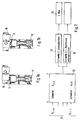
- FIGS. 1a and 1b each show a basic arrangement of a camshaft 10 associated valve 12, which is arranged by a on the camshaft 10 Pin 11 is opened or closed when the camshaft rotates.
- the valve is held in its rest position by a spring.
- the setting of the The valve is opened and the stroke size of the valve is set by a corresponding displacement of the camshaft along its longitudinal axis.
- 1a and 1b the displaceability of the camshaft along its longitudinal direction is symbolic indicated by an arrow in the axial direction in the camshaft.
- the Figure 1a shows the opening of the valve with a small or minimal stroke
- Illustration 1b shows the valve opening with maximum stroke.
- the reference symbol 20 symbolically indicates the map in which the switching thresholds for the valve control are stored.
- the characteristic diagram 20 extends over the rotational speed n and the load L applied.
- Another important input variable, which is identified in FIG. 2 by the reference symbol 21, is the transmission ratio of the transmission for power transmission, which is colloquially referred to as gear.
- the switching thresholds for switching the valve strokes and valve timing vary. If a threshold defined for the respective gear G i is exceeded, this exceeding is recognized in a working step 22 and switched over from a small to a large valve lift in a working step 23.
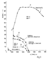
- FIG. 3 shows in more detail a speed-load map, in which different Switching thresholds for valve switching are entered. It is on the abscissa Speed n and the load L is entered on the ordinate.
- the map is three different curves 30, 31 and 32, which indicate different switching thresholds remove.
- the first curve 30 is determined by the points in a triangular shape. she specifies a first switching threshold at which the valve timing continues at minimum stroke switches from late to early.
- These switching thresholds 32 are gear-dependent and are, for example, in the application on the Engine test bench determined. At these switching thresholds, the valve timing remains the same and there is only a switchover from a small to a large valve lift. A hysteresis can advantageously be taken into account for these switching thresholds. Even when switching the valve stroke from a large to a small valve stroke the gear currently engaged in the vehicle is taken into account. In order to When braking, there is also a high level of driving comfort, which is also low Has fuel consumption.
- variable valve timing In addition to taking into account the gear engaged on the internal combustion engine at variable valve timing also has the instantaneous temperature of the Internal combustion engine has a great influence on the variable valve timing. It has shown that, especially at low temperatures, consideration of the engine temperature has a positive effect on driving behavior. As a relevant parameter for the assessment of the Temperature, the engine oil temperature is used because this temperature is a makes an actual statement about the temperature conditions prevailing in the motor.
- the engine is in a first low temperature range down to, for example, minus 30 ° C Started on a small stroke and after a stable idling speed is reached Valve controlled with a maximum or large stroke, and it also occurs at low speeds, no valve lift switchover to a small valve lift.
- Valve controlled with a maximum or large stroke and it also occurs at low speeds, no valve lift switchover to a small valve lift.
- one second middle temperature range e.g. extends from -10 ° C to + 35 ° C, remains under certain circumstances, despite different switching thresholds in the map, a large valve lift exist in order to heat the catalyst to operating temperature as quickly as possible and lower the raw emissions. Then the engine is warm and it can be used the maps stored in the control unit. Then comes one Valve control according to the switching thresholds stored in the maps.
Landscapes
- Engineering & Computer Science (AREA)
- Mechanical Engineering (AREA)
- General Engineering & Computer Science (AREA)
- Chemical & Material Sciences (AREA)
- Combustion & Propulsion (AREA)
- Output Control And Ontrol Of Special Type Engine (AREA)
- Valve Device For Special Equipments (AREA)
Abstract
Description
- Fig. 1a
- ein Prinzipschaltbild für die Realisierung eines minimalen Ventilhubes,
- Fig. 1b
- ein Prinzipschaltbild für die Realisierung eines maximalen Ventilhubes,
- Fig. 2
- eine schematische Darstellung der erfindungsgemäßen Lösung und
- Fig. 3
- ein Drehzahl-Last-Kennfeld mit eingetragenen Schaltschwellen für die Änderung der Ventilsteuerung.
Beim Durchfahren der einzelnen Betriebsbereiche variieren somit die Schaltschwellen für die Umschaltung der Ventilhübe und der Ventilsteuerzeiten. Beim Überschreiten einer für den jeweiligen Gang Gi festgelegten Schwelle, wird in einem Arbeitsschritt 22 dieses Überschreiten erkannt und in einem Arbeitsschritt 23 von einem kleinen auf einen großen Ventilhub umschaltet. Das spätere wieder Unterschreiten der Schaltschwelle wird in einem Arbeitsschritt 24 erkannt und die Ventilhubumschaltung erfolgt wieder von groß zu klein. Für einen optimalen gleichmäßigen Drehmomentverlauf, erfolgt die Umschaltung des Ventilhubes von groß zurück auf klein nicht genau beim Unterschreiten der abgespeicherten Schaltschwelle für das Hochschalten sondern es wird noch eine vorgebbare Differenz berücksichtigt, so daß das Schaltverhalten der Ventile in einer Hysterese verläuft. Durch dieses Schaltverhalten wird sichergestellt, daß ein kontinuierlicher Drehmomentenverlauf sowohl beim Hochschalten als auch beim Herunterschalten von einem Gang in den anderen gewährleistet ist.
Claims (4)
- Brennkraftmaschine mit einer Einrichtung zur variablen Ventilsteuerung, wobei die Ventilsteuerzeiten und die Ventilhübe in Abhängigkeit der Betriebsparameter der Brennkraftmaschine festlegbar sind, wobei die Schaltschwellen für die Änderung der Ventilsteuerzeiten und/oder der Ventilhübe in einem Kennfeld, welches sich über die Drehzahl und die Last aufspannt, abgelegt sind, dadurch gekennzeichnet, die Schaltschwellen in Abhängigkeit des aktuell eingelegten Ganges und/oder temperaturabhängig veränderbar sind.
- Brennkraftmaschine nach Anspruch 1, dadurch gekennzeichnet, daß die Ermittlung der Schaltschwellen in der Applikation erfolgt.
- Brennkraftmaschine nach Anspruch 1, dadurch gekennzeichnet, daß die gangabhängige Schaltschwelle jeweils einen ruckfreien Betrieb der Brennkraftmaschine beim Hubwechsel gewährleistet.
- Brennkraftmaschine nach einem der vorherigen Ansprüche, dadurch gekennzeichnet, daß die Hysterese für ein Rückschalten des Ventilhubes gangabhängig definiert ist.
Applications Claiming Priority (4)
| Application Number | Priority Date | Filing Date | Title |
|---|---|---|---|
| DE19942746 | 1999-09-08 | ||
| DE19942746 | 1999-09-10 | ||
| DE10002771A DE10002771A1 (de) | 1999-09-10 | 2000-01-22 | Ventilsteuerung bei Brennkraftmaschinen |
| DE10002771 | 2000-01-22 |
Publications (3)
| Publication Number | Publication Date |
|---|---|
| EP1083303A2 true EP1083303A2 (de) | 2001-03-14 |
| EP1083303A3 EP1083303A3 (de) | 2003-01-22 |
| EP1083303B1 EP1083303B1 (de) | 2005-01-12 |
Family
ID=26003984
Family Applications (1)
| Application Number | Title | Priority Date | Filing Date |
|---|---|---|---|
| EP00117063A Expired - Lifetime EP1083303B1 (de) | 1999-09-08 | 2000-08-09 | Ventilsteuerung bei Brennkraftmaschinen |
Country Status (3)
| Country | Link |
|---|---|
| US (1) | US6343578B1 (de) |
| EP (1) | EP1083303B1 (de) |
| ES (1) | ES2231092T3 (de) |
Cited By (4)
| Publication number | Priority date | Publication date | Assignee | Title |
|---|---|---|---|---|
| CN103352736A (zh) * | 2013-07-11 | 2013-10-16 | 浙江大学 | 一种连续可变气门升程机构 |
| CN110094268A (zh) * | 2018-01-30 | 2019-08-06 | 丰田自动车株式会社 | 内燃机的控制装置 |
| DE102007021947B4 (de) | 2006-06-30 | 2023-03-02 | Harley-Davidson Motor Company Group, LLC | Zylinderdeaktivierung für einen Motorradmotor |
| DE102024119330A1 (de) | 2024-07-08 | 2026-01-08 | Bayerische Motoren Werke Aktiengesellschaft | Verbrennungsmotorsteuerungsverfahren und Verbrennungsmotor |
Families Citing this family (11)
| Publication number | Priority date | Publication date | Assignee | Title |
|---|---|---|---|---|
| JP2003286869A (ja) | 2002-03-27 | 2003-10-10 | Toyota Motor Corp | 筒内噴射式火花点火内燃機関 |
| US8596398B2 (en) | 2007-05-16 | 2013-12-03 | Polaris Industries Inc. | All terrain vehicle |
| DE102007052254B4 (de) * | 2007-11-02 | 2021-02-04 | Daimler Ag | Ventiltriebvorrichtung |
| US8994494B2 (en) | 2008-10-10 | 2015-03-31 | Polaris Industries Inc. | Vehicle security system |
| US10358187B2 (en) | 2014-01-10 | 2019-07-23 | Polaris Industries Inc. | Snowmobile |
| US9506407B2 (en) * | 2014-01-10 | 2016-11-29 | Polaris Industries Inc. | Engine having active exhaust valve position control system and method |
| EP2812236B1 (de) | 2012-02-09 | 2016-11-02 | Polaris Industries Inc. | Schneemobil |
| US9845004B2 (en) | 2014-01-10 | 2017-12-19 | Polaris Industries Inc. | Snowmobile |
| US10793181B2 (en) | 2018-02-13 | 2020-10-06 | Polaris Industries Inc. | All-terrain vehicle |
| CN114704347B (zh) * | 2021-04-01 | 2023-01-24 | 长城汽车股份有限公司 | 可变气门升程机构控制方法及终端设备 |
| CN114033524B (zh) * | 2021-11-09 | 2022-09-27 | 上海汽车集团股份有限公司 | 两阶段可变气门升程控制方法及系统 |
Citations (1)
| Publication number | Priority date | Publication date | Assignee | Title |
|---|---|---|---|---|
| DE19814888A1 (de) | 1997-04-02 | 1998-11-05 | Mitsubishi Motors Corp | Variabler Ventilsteuerungsmechanismus |
Family Cites Families (17)
| Publication number | Priority date | Publication date | Assignee | Title |
|---|---|---|---|---|
| US4009695A (en) * | 1972-11-14 | 1977-03-01 | Ule Louis A | Programmed valve system for internal combustion engine |
| JPS54121314A (en) * | 1978-03-13 | 1979-09-20 | Toyota Motor Corp | Valve lift varying mechanism for internal combustion engine |
| JPS5838602B2 (ja) * | 1979-05-09 | 1983-08-24 | トヨタ自動車株式会社 | 可変バルブ機関の制御装置 |
| DE4014401C1 (de) * | 1990-05-04 | 1991-03-21 | Dr.Ing.H.C. F. Porsche Ag, 7000 Stuttgart, De | |
| DE69316285T2 (de) * | 1992-02-28 | 1998-08-27 | Mitsubishi Motors Corp | Steuervorrichtung für eine brennkraftmaschine mit veränderbarer ein- und auslassventilsteuervorrichtung und verfahren zur steuerung dafür |
| EP0583584B1 (de) * | 1992-07-16 | 1996-04-03 | Mitsubishi Jidosha Kogyo Kabushiki Kaisha | Ventilsteuerungsvorrichtung mit Mechanismus zur Veränderung der Ventilsteuerzeit |
| JPH0777073A (ja) * | 1993-09-09 | 1995-03-20 | Toyota Motor Corp | 内燃機関のバルブタイミング制御装置 |
| JP3119050B2 (ja) * | 1993-09-28 | 2000-12-18 | トヨタ自動車株式会社 | 内燃機関のバルブタイミング制御装置 |
| FR2712026B1 (fr) * | 1993-11-05 | 1996-01-12 | Siemens Automotive Sa | Procédé et dispositif de commande de la levée d'une soupape d'un moteur à combustion interne. |
| GB2293894B (en) * | 1994-10-03 | 1998-05-13 | Ford Motor Co | Variable camshaft timing system |
| JPH08270470A (ja) * | 1995-03-31 | 1996-10-15 | Toyota Motor Corp | 内燃機関のバルブタイミング制御装置 |
| WO1996037689A1 (fr) * | 1995-05-25 | 1996-11-28 | Mitsubishi Jidosha Kogyo Kabushiki Kaisha | Train ajustable d'engrenages de commande de soupapes |
| JP3612379B2 (ja) * | 1996-04-10 | 2005-01-19 | 三菱自動車工業株式会社 | 可変動弁機構用駆動装置及び油圧アクチュエータ |
| DE19624230C1 (de) * | 1996-06-18 | 1997-07-10 | Porsche Ag | Ventilsteuerung für Brennkraftmaschinen |
| JP3899576B2 (ja) * | 1997-02-07 | 2007-03-28 | 三菱自動車工業株式会社 | 可変動弁機構及び可変動弁機構付き内燃機関 |
| JP3985375B2 (ja) * | 1999-01-14 | 2007-10-03 | 日産自動車株式会社 | エンジンの吸気制御装置 |
| JP3059170B1 (ja) * | 1999-09-13 | 2000-07-04 | 三菱電機株式会社 | 内燃機関におけるバルブタイミング制御装置 |
-
2000
- 2000-08-09 ES ES00117063T patent/ES2231092T3/es not_active Expired - Lifetime
- 2000-08-09 EP EP00117063A patent/EP1083303B1/de not_active Expired - Lifetime
- 2000-09-08 US US09/658,266 patent/US6343578B1/en not_active Expired - Fee Related
Patent Citations (1)
| Publication number | Priority date | Publication date | Assignee | Title |
|---|---|---|---|---|
| DE19814888A1 (de) | 1997-04-02 | 1998-11-05 | Mitsubishi Motors Corp | Variabler Ventilsteuerungsmechanismus |
Cited By (4)
| Publication number | Priority date | Publication date | Assignee | Title |
|---|---|---|---|---|
| DE102007021947B4 (de) | 2006-06-30 | 2023-03-02 | Harley-Davidson Motor Company Group, LLC | Zylinderdeaktivierung für einen Motorradmotor |
| CN103352736A (zh) * | 2013-07-11 | 2013-10-16 | 浙江大学 | 一种连续可变气门升程机构 |
| CN110094268A (zh) * | 2018-01-30 | 2019-08-06 | 丰田自动车株式会社 | 内燃机的控制装置 |
| DE102024119330A1 (de) | 2024-07-08 | 2026-01-08 | Bayerische Motoren Werke Aktiengesellschaft | Verbrennungsmotorsteuerungsverfahren und Verbrennungsmotor |
Also Published As
| Publication number | Publication date |
|---|---|
| US6343578B1 (en) | 2002-02-05 |
| ES2231092T3 (es) | 2005-05-16 |
| EP1083303A3 (de) | 2003-01-22 |
| EP1083303B1 (de) | 2005-01-12 |
Similar Documents
| Publication | Publication Date | Title |
|---|---|---|
| EP1083303B1 (de) | Ventilsteuerung bei Brennkraftmaschinen | |
| DE68910777T2 (de) | Sicherheitsverfahren zusammen mit Ventilzeitsteuerung bei Innenverbrennungsmotoren. | |
| DE19501386C2 (de) | Verfahren zum Steuern einer fremdgezündeten, mit einer Kraftstoffeinspritzanlage ausgerüsteten Kolbenbrennkraftmaschine | |
| DE3621080C3 (de) | Ventilzeitsteuerungsvorrichtung für Verbrennungsmotoren mit mehreren Einlaßventilen pro Zylinder | |
| EP0779427B1 (de) | Verfahren zum Ab- und Zuschalten einzelner Zylinder einer Mehrzylinderbrennkraftmaschine | |
| DE19630053B4 (de) | Verfahren und Vorrichtung zur kontinuierlichen und variablen Regelung einer Ventileinstellung eines Verbrennungsmotors | |
| DE69804297T2 (de) | Vorrichtung zum verstellen des hubvolumens und/oder des effektiven verdichtungsverhältnisses einer brennkraftmaschine während des betriebs | |
| DE19713460B4 (de) | Steuersystem für Automatikgetriebe | |
| DE4223910C5 (de) | Ventilmechanismus für Brennkraftmaschinen | |
| DE19814888A1 (de) | Variabler Ventilsteuerungsmechanismus | |
| DE102006034576B4 (de) | Verbessern der Antriebsstrang-Schaltqualität bei mit einem Motor mit variablem Ventiltrieb ausgestatteten Antriebssträngen | |
| DE10120293B4 (de) | Leitungsdruck-Regelvorrichtung für ein stufenloses Getriebe | |
| DE69020159T2 (de) | Drucksteuervorrichtung für ein automatisches Kraftfahrzeuggetriebe. | |
| DE3835333A1 (de) | Konzept zur variablen ventilsteuerung auf basis von nockenwellenphasenverschiebung | |
| EP0888921A2 (de) | Steuerung für den Antriebsstrang eines Kraftfahrzeugs | |
| DE4123017A1 (de) | Leitungsdrucksteuerung beim anwerfen und bei nachfolgendem warmlaufbetrieb eines motors | |
| EP0730105B1 (de) | Steuereinrichtung zur Regelung des Schliessvorganges einer Trennkupplung für Kraftfahrzeuge | |
| DE10137367B4 (de) | Ventilzeitgabe-Steuersystem für einen Verbrennungsmotor | |
| DE102004022593B4 (de) | Verfahren und Vorrichtung zum Steuern einer Brennkraftmaschine | |
| DE19958207B4 (de) | EGR-Steuerung für einen Motor mit Zylinderabschaltung | |
| EP1331382A2 (de) | Verfahren, Computerprogramm und Steuer und/oder Regelgerät zum Betreiben einer Brennkraftmaschine, sowie Brennkraftmaschine | |
| DE10138048A1 (de) | Ventilzeitgabe-Steuersystem für einen Verbrennungsmotor | |
| DE10002771A1 (de) | Ventilsteuerung bei Brennkraftmaschinen | |
| DE602005000417T2 (de) | Leerlaufdrehzahlregelvorrichtung für Kraftfahrzeugmotor | |
| DE2522242A1 (de) | Kraftfahrzeug mit einer brennkraftmaschine und einem automatischen getriebe |
Legal Events
| Date | Code | Title | Description |
|---|---|---|---|
| PUAI | Public reference made under article 153(3) epc to a published international application that has entered the european phase |
Free format text: ORIGINAL CODE: 0009012 |
|
| AK | Designated contracting states |
Kind code of ref document: A2 Designated state(s): AT BE CH CY DE DK ES FI FR GB GR IE IT LI LU MC NL PT SE |
|
| AX | Request for extension of the european patent |
Free format text: AL;LT;LV;MK;RO;SI |
|
| PUAL | Search report despatched |
Free format text: ORIGINAL CODE: 0009013 |
|
| AK | Designated contracting states |
Kind code of ref document: A3 Designated state(s): AT BE CH CY DE DK ES FI FR GB GR IE IT LI LU MC NL PT SE |
|
| AX | Request for extension of the european patent |
Free format text: AL;LT;LV;MK;RO;SI |
|
| RIC1 | Information provided on ipc code assigned before grant |
Free format text: 7F 01L 31/00 A, 7F 02D 41/14 B, 7F 01L 13/00 B, 7F 01L 1/34 B, 7F 02D 13/02 B |
|
| 17P | Request for examination filed |
Effective date: 20030722 |
|
| AKX | Designation fees paid |
Designated state(s): DE ES FR GB IT |
|
| 17Q | First examination report despatched |
Effective date: 20031209 |
|
| GRAP | Despatch of communication of intention to grant a patent |
Free format text: ORIGINAL CODE: EPIDOSNIGR1 |
|
| GRAS | Grant fee paid |
Free format text: ORIGINAL CODE: EPIDOSNIGR3 |
|
| GRAA | (expected) grant |
Free format text: ORIGINAL CODE: 0009210 |
|
| AK | Designated contracting states |
Kind code of ref document: B1 Designated state(s): DE ES FR GB IT |
|
| REG | Reference to a national code |
Ref country code: GB Ref legal event code: FG4D Free format text: NOT ENGLISH |
|
| REF | Corresponds to: |
Ref document number: 50009200 Country of ref document: DE Date of ref document: 20050217 Kind code of ref document: P |
|
| REG | Reference to a national code |
Ref country code: IE Ref legal event code: FG4D Free format text: GERMAN |
|
| REG | Reference to a national code |
Ref country code: ES Ref legal event code: FG2A Ref document number: 2231092 Country of ref document: ES Kind code of ref document: T3 |
|
| GBT | Gb: translation of ep patent filed (gb section 77(6)(a)/1977) |
Effective date: 20050422 |
|
| ET | Fr: translation filed | ||
| PLBE | No opposition filed within time limit |
Free format text: ORIGINAL CODE: 0009261 |
|
| STAA | Information on the status of an ep patent application or granted ep patent |
Free format text: STATUS: NO OPPOSITION FILED WITHIN TIME LIMIT |
|
| 26N | No opposition filed |
Effective date: 20051013 |
|
| PGFP | Annual fee paid to national office [announced via postgrant information from national office to epo] |
Ref country code: ES Payment date: 20080828 Year of fee payment: 9 |
|
| REG | Reference to a national code |
Ref country code: FR Ref legal event code: TP |
|
| REG | Reference to a national code |
Ref country code: FR Ref legal event code: CD |
|
| REG | Reference to a national code |
Ref country code: ES Ref legal event code: FD2A Effective date: 20090810 |
|
| PGFP | Annual fee paid to national office [announced via postgrant information from national office to epo] |
Ref country code: IT Payment date: 20100823 Year of fee payment: 11 Ref country code: FR Payment date: 20100901 Year of fee payment: 11 |
|
| PGFP | Annual fee paid to national office [announced via postgrant information from national office to epo] |
Ref country code: GB Payment date: 20100819 Year of fee payment: 11 |
|
| REG | Reference to a national code |
Ref country code: FR Ref legal event code: TP |
|
| REG | Reference to a national code |
Ref country code: GB Ref legal event code: 732E Free format text: REGISTERED BETWEEN 20110310 AND 20110316 |
|
| REG | Reference to a national code |
Ref country code: GB Ref legal event code: 732E Free format text: REGISTERED BETWEEN 20110331 AND 20110406 |
|
| PG25 | Lapsed in a contracting state [announced via postgrant information from national office to epo] |
Ref country code: ES Free format text: LAPSE BECAUSE OF NON-PAYMENT OF DUE FEES Effective date: 20090810 |
|
| GBPC | Gb: european patent ceased through non-payment of renewal fee |
Effective date: 20110809 |
|
| REG | Reference to a national code |
Ref country code: FR Ref legal event code: ST Effective date: 20120430 |
|
| PG25 | Lapsed in a contracting state [announced via postgrant information from national office to epo] |
Ref country code: IT Free format text: LAPSE BECAUSE OF NON-PAYMENT OF DUE FEES Effective date: 20110809 |
|
| PG25 | Lapsed in a contracting state [announced via postgrant information from national office to epo] |
Ref country code: GB Free format text: LAPSE BECAUSE OF NON-PAYMENT OF DUE FEES Effective date: 20110809 Ref country code: FR Free format text: LAPSE BECAUSE OF NON-PAYMENT OF DUE FEES Effective date: 20110831 |
|
| PGFP | Annual fee paid to national office [announced via postgrant information from national office to epo] |
Ref country code: DE Payment date: 20150730 Year of fee payment: 16 |
|
| REG | Reference to a national code |
Ref country code: DE Ref legal event code: R119 Ref document number: 50009200 Country of ref document: DE |
|
| PG25 | Lapsed in a contracting state [announced via postgrant information from national office to epo] |
Ref country code: DE Free format text: LAPSE BECAUSE OF NON-PAYMENT OF DUE FEES Effective date: 20170301 |