EP1083260A2 - Doppelsiebformer - Google Patents
Doppelsiebformer Download PDFInfo
- Publication number
- EP1083260A2 EP1083260A2 EP00116688A EP00116688A EP1083260A2 EP 1083260 A2 EP1083260 A2 EP 1083260A2 EP 00116688 A EP00116688 A EP 00116688A EP 00116688 A EP00116688 A EP 00116688A EP 1083260 A2 EP1083260 A2 EP 1083260A2
- Authority
- EP
- European Patent Office
- Prior art keywords
- twin
- wire
- applicator
- fourdrinier
- wire former
- Prior art date
- Legal status (The legal status is an assumption and is not a legal conclusion. Google has not performed a legal analysis and makes no representation as to the accuracy of the status listed.)
- Granted
Links
Images


Classifications
-
- D—TEXTILES; PAPER
- D21—PAPER-MAKING; PRODUCTION OF CELLULOSE
- D21F—PAPER-MAKING MACHINES; METHODS OF PRODUCING PAPER THEREON
- D21F9/00—Complete machines for making continuous webs of paper
- D21F9/003—Complete machines for making continuous webs of paper of the twin-wire type
Definitions
- the invention relates to a twin wire former of a machine for production a fibrous web, in particular a paper or cardboard web, with two revolving endless sieves, forming one The inlet gap converge.
- Twin wire formers of this type are known, for example, from DE 41 02 065 C2 and DE 198 23 724 A1.
- Gapformer used to drain the pulp suspension to care.
- the fibrous web is used for further mechanical drainage in the Press section led.
- the horizontal or oblique Gapformer can use a vertical gap former to suspend both Sides are drained under the same conditions. This means, that gravity in this case affects drainage in the same way affects both sides, so that e.g. a preference for Bottom is excluded.
- the aim of the invention is to provide a twin wire former of the type mentioned Type to create, which with a high efficiency a strong bilateral filler in the near-surface layers of a fibrous web or a paper structure.
- twin wire sections adjoining the material inlet gap, the runs exactly vertically or at an angle ⁇ to the vertical V, where this angle ⁇ expediently in a range of about -30 ° to about + 30 °, in particular in a range from about -20 ° to about + 20 ° and is preferably in a range from about -5 ° to about + 5 °
- two twin-wire sides each have at least one applicator for application a filler suspension is provided, and preferably each applicator one suction element provided on the other twin wire side opposite.
- the filler suspension preferably contains filler and water.
- At least one or any combination of the following materials is provided as the filler: kaolins, clays, CaCO 3 (ground -GCC, or precipitated - PCC), zeolites, TiO 2 , bentonites and / or other mineral substances.
- the Filler suspension also contain fine and fibrous materials.
- Retention agents and / or other processing agents can be used to increase the Retention can be used.
- Twin wire former is one of the most popular in the area of the inlet gap both sieves passed over a vacuum forming roll and the twin wire following in one within the at least the essential vertical twin wire section forming area.
- the suspension is thus initially dewatered via the vacuum-forming roller.
- the forming area preferably comprises at least one forming shoe.
- Such a formation shoe advantageously consists of one or more Zones, in particular from 1 to 4 zones and preferably from 1 to 3 zones.
- the drainage and equalization of the fibrous web or Paper structure over the forming shoe is preferably carried out with the help of suctioned drainage elements and formation strips.
- the subsequent further dewatering of the fibrous web preferably carried out over a wire suction roll.
- At least one applicator is provided, which one on the other double screen side provided flat suction.
- At least one applicator is provided which is opposite a forming shoe provided on the other twin wire side.
- At least one applicator is expediently provided, one on the other twin wire side of the screen suction roll.
- twin wire former becomes that after the application of the filler suspension White water separate from that before applying the filler suspension resulting white water recorded and treated. So it can two qualities of white water are recorded and processed separately. A large part of the filler-rich white water can be used directly be used to dilute the filler lurry. This will Circuit almost closed.
- the inlet gap is generally below the minimum essentially vertical twin wire section.
- FIGS 1 to 7 show different embodiments of a twin wire former 10 a machine for producing a fibrous web 12, which is, in particular, a paper or cardboard web can.
- the twin-wire former 10 comprises an all-round endless bottom wire 14 and an encircling endless top wire 16 forming a stock entry nip 18 converge.
- the lower wire 14 is over a Breast roll 20 and the top wire 16 via a suction-forming roll 22 guided.
- the inlet gap 18 lying below is opened 24 stock suspension introduced from below.
- At least essentially vertical twin-wire section 24 is an applicator 26 for application on both twin wire sides a filler suspension provided.
- At the top of at least in The essential vertical twin wire section 24 is the twin wire over a Sieve suction roll 28 out.
- this screen suction roller 28 In the outlet area of this screen suction roller 28 the two screens 14, 16 are separated from one another, the lower screen 14 obliquely downwards and the top wire 16 via a deflection roller 30 is led away above.
- twin wire 14, 16 into one within the at least substantially vertical Twin wire section 24 lying, for example at least one Forming shoe 32 guided forming area.
- This formation area or formation shoe 32 can consist of one or more zones, in particular consist of 1 to 4 zones and preferably 1 to 3 zones.
- the forming shoe each comprises three zones 32 ', 32' 'and 32' ''.
- a filler suspension containing in particular filler and water is applied uniformly over the web width.
- Kaolin, clays, CaCO 3 (ground -GCC, or precipitated -PCC), zeolites, TiO 2 , bentonites and / or other mineral substances and any combination of these or a part of these materials can be used as fillers. If white water is used to dilute the filler, the filler suspension may also contain fine and fibrous materials. Retention agents and / or other process aids can be used to increase the retention.
- the applicators 26 are each opposite one another in the twin-wire area 24 Suction element such as a flat suction pad 34, the Siebsaugwalze 28 or the forming shoe 32, over which the Drainage and homogenization of the fibrous web 12 with the help of suctioned drainage elements and formation strips 36 can.
- the filler suspension is made by means of the relevant suction element by the between the relevant applicator 26 and the Fibrous web 12 lying sieve 14 or 16 sucked.
- the pulp suspension is initially between the two screens 14, 16 dewatered over the suction forming roll 22 and then in the forming area comprising, for example, a forming shoe 32 guided. Further dewatering takes place over the forming shoe 32 Uniformity of the structure with the help of suctioned drainage elements and the formation strips 36. Then the fibrous web 12 with the help of a flat suction cup 34, and then over the suction Sieve suction roller 28 can be further dewatered.
- the one adjoining the stock inlet gap 18 Twin wire section 24 exactly vertical or under a certain Angles ⁇ extend to the vertical V, this angle ⁇ , for example in a range from approximately -30 ° to approximately + 30 °, in particular in a range from about -20 ° to about + 20 ° and preferably in a range of is about -5 ° to about + 5 °.
- an applicator 26 is provided, which is arranged on the side of the top wire 16 Flat suction cup 34 is opposite. Another is on top of that Applicator 26 of the screen suction roll 28 provided on the top screen 16 side across from.
- FIG. 3 differs from that of the figure 2 only in that the closer to the forming shoe 32 is provided Applicator 26 is now arranged on the side of the top wire 16, while the applicator 26 provided closer to the screen suction roll 28 is arranged on the side of the lower wire 14. Both applicators are also located here 26 each opposite a flat suction cup 34.
- one is on the side of the top wire 16 provided applicator 26 opposite the forming shoe 32, while another applicator provided on the top wire 14 side 26 is again opposite a flat suction cup 34. Otherwise owns this embodiment at least essentially the same structure as the previous embodiment, but corresponding to each other Parts are assigned the same reference numerals again.
- FIG. 5 differs from that of the figure 1 only in that the forming shoe 32 instead of on the side of Lower sieve 14 is now arranged on the side of the upper sieve 16.
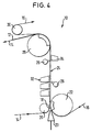
- one is on the side of the lower wire 14 provided applicator 26 opposite the forming shoe 32, while another applicator provided on the top wire 16 side 26 of the screen suction roller 28 is opposite.
- FIG. 7 differs from that of the figure 3 essentially only in that the forming shoe 32 instead of on the Side of the lower wire 14 is now arranged on the side of the upper wire 16 is.
- FIGS 7 Any combinations of those in FIGS 7 illustrated embodiments conceivable.
- the white water obtained after application of the filler suspension separately from that which occurs before application of the filler suspension White water can be recorded and treated. So there can be two white water qualities recorded and processed separately. A large Part of the filler-rich white water can be used for dilution the filler lurry can be used. This will make the cycle almost closed.
Landscapes
- Paper (AREA)
- Thermal Transfer Or Thermal Recording In General (AREA)
Abstract
Description
- Figur 1
- eine schematische Darstellung einer ersten Ausführungsform eines Doppelsiebformers mit einem einem Flachsauger gegenüberliegenden Applikator und einem einer Siebsaugwalze gegenüberliegenden Applikator,
- Figur 2
- eine schematische Darstellung einer weiteren Ausführungsform eines Doppelsiebformers mit zwei jeweils einem Flachsauger gegenüberliegenden Applikatoren, wobei der näher beim Formierschuh vorgesehene Applikator auf der Seite des Untersiebs und der näher bei der Siebsaugwalze vorgesehene Applikator auf der Seite des Obersiebs angeordnet ist,
- Figur 3
- eine schematische Darstellung einer weiteren Ausführungsform eines Doppelsiebformers mit zwei jeweils einem Flachsauger gegenüberliegenden Applikatoren, wobei der näher beim Formschuh vorgesehene Applikator auf der Seite des Obersiebs und der näher bei der Siebsaugwalze vorgesehene Applikator auf der Seite des Untersiebs angeordnet ist,
- Figur 4
- eine schematische Darstellung einer weiteren Ausführungsform eines Doppelsiebformers mit einem dem Formierschuh gegenüberliegenden Applikator und einem einem Flachsauger gegenüberliegenden Applikator,
- Figur 5
- eine schematische Darstellung einer mit der der Figur 1 vergleichbaren weiteren Ausführungsform eines Doppelsiebformers, wobei jedoch der Formierschuh auf der Seite des Obersiebs vorgesehen ist,
- Figur 6
- eine schematische Darstellung einer weiteren Ausführungsform eine Doppelsiebformers mit einem dem Formierschuh gegenüberliegenden Applikator und einem der Siebsaugwalze gegenüberliegenden Applikator und
- Figur 7
- eine schematische Darstellung einer mit der der Figur 3 vergleichbaren weiteren Ausführungsform eines Doppelsiebformers, wobei jedoch der Formierschuh auf der Seite des Obersiebs vorgesehen ist.
- 10
- Doppelsiebformer
- 12
- Faserstoffbahn
- 14
- Untersieb
- 16
- Obersieb
- 18
- Stoffeinlaufspalt
- 20
- Brustwalze
- 22
- Formierwalze
- 24
- Vertikale Doppelsiebstrecke
- 26
- Applikator
- 28
- Siebsaugwalze
- 30
- Umlenkwalze
- 32
- Formierbereich, Formschuh
- 32', 32'', 32'''
- Zonen
- 34
- Flachsauger
- 36
- Formationsleisten
- V
- Vertikale
Claims (15)
- Doppelsiebformer (10) einer Maschine zur Herstellung einer Faserstoffbahn (12), insbesondere einer Papier- oder Kartonbahn, mit zwei umlaufenden endlosen Sieben (14, 16), die unter Bildung eines Stoffeinlaufspaltes (18) zusammenlaufen,
dadurch gekennzeichnet,
daß innerhalb einer sich an den Stoffeinlaufspalt (18) anschließenden Doppelsiebstrecke (24), die genau vertikal oder unter einem Winkel (α) zur Vertikalen (V) verläuft, wobei dieser Winkel (α) zweckmäßigerweise in einem Bereich von etwa -30° bis etwa +30°, insbesondere in einem Bereich von etwa -20° bis etwa +20° und vorzugsweise in einem Bereich von etwa -5° bis etwa +5° liegt, auf beiden Doppelsiebseiten jeweils wenigstens ein Applikator (26) zum Auftragen einer Füllstoffsuspension vorgesehen ist und vorzugsweise jeder Applikator (26) jeweils einem auf der anderen Doppelsiebseite vorgesehenen Saugerelement (28, 32, 34) gegenüberliegt. - Doppelsiebformer (10) nach Anspruch 1,
dadurch gekennzeichnet,
daß die Füllstoffsuspension Füllstoff und Wasser enthält. - Doppelsiebformer (10) nach Anspruch 1 oder 2,
dadurch gekennzeichnet,
daß als Füllstoff zumindest eines oder eine beliebige Kombination aus den folgenden Materialien vorgesehen ist: Kaoline, Clays, CaCO3 (gemahlen -GCC, oder gefällt -PCC), Zeolithe, TiO2, Bentonite und/oder andere mineralische Stoffe. - Doppelsiebformer (10) nach einem der vorhergehenden Ansprüche,
dadurch gekennzeichnet,
daß die Füllstoffsuspension überdies Fein- und Faserstoffe enthält. - Doppelsiebformer (10) nach einem der vorhergehenden Ansprüche,
dadurch gekennzeichnet,
daß die Füllstoffsuspension überdies Retentionsmittel und/oder andere Prozeßhilfsmittel enthält. - Doppelsiebformer (10) nach einem der vorhergehenden Ansprüche,
dadurch gekennzeichnet,
daß im Bereich des Stoffeinlaufspaltes (18) eines (16) der beiden Siebe (14, 16) über eine besaugte Formierwalze (20) geführt und das Doppelsieb (14, 16) im Anschluß daran in einen innerhalb der zumindest im wesentlichen vertikalen Doppelsiebstrecke (24) liegenden Formierbereich (32) geführt ist. - Doppelsiebformer (10) nach einem der vorhergehenden Ansprüche,
dadurch gekennzeichnet,
daß der Formierbereich wenigstens einen Formierschuh (32) umfaßt. - Doppelsiebformer (10) nach Anspruch 7,
dadurch gekennzeichnet,
daß der Formierschuh (32) aus einer oder mehreren Zonen, insbesondere aus 1 bis 4 Zonen und vorzugsweise aus 1 bis 3 Zonen (32', 32'', 32''') besteht. - Doppelsiebformer (10) nach einem der vorhergehenden Ansprüche,
dadurch gekennzeichnet,
daß die Entwässerung und Vergleichmäßigung der Faserstoffbahn (12) über dem Formierschuh (32) mit Hilfe von besaugten Entwässerungselementen sowie Formationsleisten (36) erfolgt. - Doppelsiebformer (10) nach einem der vorhergehenden Ansprüche,
dadurch gekennzeichnet,
daß zur weiteren Entwässerung der Faserstoffbahn (12) im Anschluß an den Formierbereich (32) innerhalb der zumindest im wesentlichen vertikalen Doppelsiebstrecke (24) wenigstens ein Flachsauger (34) vorgesehen ist und die anschließende weitere Entwässerung der Faserstoffbahn (12) vorzugsweise über einer Siebsaugwalze (28) erfolgt. - Doppelsiebformer (10) nach einem der vorhergehenden Ansprüche,
dadurch gekennzeichnet,
daß wenigstens ein Applikator (26) vorgesehen ist, der einem auf der anderen Doppelsiebseite vorgesehenen Flachsauger (34) gegenüberliegt. - Doppelsiebformer (10) nach einem der vorhergehenden Ansprüche,
dadurch gekennzeichnet,
daß wenigstens ein Applikator (26) vorgesehen ist, der einem auf der anderen Doppelsiebseite vorgesehenen Formierschuh (32) gegenüberliegt. - Doppelsiebformer (10) nach einem der vorhergehenden Ansprüche,
dadurch gekennzeichnet,
daß wenigstens ein Applikator (26) vorgesehen ist, der einer auf der anderen Doppelsiebseite vorgesehenen Siebsaugwalze (28) gegenüberliegt. - Doppelsiebformer (10) nach einem der vorhergehenden Ansprüche,
dadurch gekennzeichnet,
daß das nach dem Auftragen der Füllstoffsuspension anfallende Siebwasser getrennt von dem vor dem Auftragen der Füllstoffsuspension anfallenden Siebwasser erfaßt und behandelt wird. - Doppelsiebformer (10) nach einem der vorhergehenden Ansprüche,
dadurch gekennzeichnet,
daß der Stoffeinlaufspalt (18) allgemein unterhalb der zumindest im wesentlichen vertikalen Doppelsiebstrecke (24) liegt.
Applications Claiming Priority (2)
| Application Number | Priority Date | Filing Date | Title |
|---|---|---|---|
| DE19943369 | 1999-09-10 | ||
| DE19943369A DE19943369A1 (de) | 1999-09-10 | 1999-09-10 | Doppelsiebformer |
Publications (3)
| Publication Number | Publication Date |
|---|---|
| EP1083260A2 true EP1083260A2 (de) | 2001-03-14 |
| EP1083260A3 EP1083260A3 (de) | 2001-07-11 |
| EP1083260B1 EP1083260B1 (de) | 2004-11-03 |
Family
ID=7921529
Family Applications (1)
| Application Number | Title | Priority Date | Filing Date |
|---|---|---|---|
| EP00116688A Expired - Lifetime EP1083260B1 (de) | 1999-09-10 | 2000-08-02 | Doppelsiebformer |
Country Status (3)
| Country | Link |
|---|---|
| EP (1) | EP1083260B1 (de) |
| AT (1) | ATE281556T1 (de) |
| DE (2) | DE19943369A1 (de) |
Cited By (1)
| Publication number | Priority date | Publication date | Assignee | Title |
|---|---|---|---|---|
| EP1683913A1 (de) * | 2005-01-25 | 2006-07-26 | Voith Paper Patent GmbH | Doppelsiebformer |
Families Citing this family (2)
| Publication number | Priority date | Publication date | Assignee | Title |
|---|---|---|---|---|
| DE10335361A1 (de) * | 2003-08-01 | 2005-02-17 | Voith Paper Patent Gmbh | Doppelsiebformer |
| CN101775753B (zh) * | 2010-03-30 | 2013-04-10 | 陕西科技大学 | 纸张抄造过程中的加填方法及其装置 |
Citations (3)
| Publication number | Priority date | Publication date | Assignee | Title |
|---|---|---|---|---|
| DE6932836U (de) * | 1969-08-20 | 1971-12-30 | Voith Gmbh J M | Siebpartie einer papiermaschine mit einem applikator. |
| DE4102065A1 (de) * | 1991-01-24 | 1992-07-30 | Escher Wyss Gmbh | Doppelsiebformer |
| DE19823724A1 (de) * | 1997-10-24 | 1999-04-29 | Voith Sulzer Papiertech Patent | Verfahren und Vorrichtung zum Auftragen eines Mediums auf eine laufende Materialbahn |
-
1999
- 1999-09-10 DE DE19943369A patent/DE19943369A1/de not_active Withdrawn
-
2000
- 2000-08-02 DE DE50008487T patent/DE50008487D1/de not_active Expired - Lifetime
- 2000-08-02 AT AT00116688T patent/ATE281556T1/de active
- 2000-08-02 EP EP00116688A patent/EP1083260B1/de not_active Expired - Lifetime
Patent Citations (3)
| Publication number | Priority date | Publication date | Assignee | Title |
|---|---|---|---|---|
| DE6932836U (de) * | 1969-08-20 | 1971-12-30 | Voith Gmbh J M | Siebpartie einer papiermaschine mit einem applikator. |
| DE4102065A1 (de) * | 1991-01-24 | 1992-07-30 | Escher Wyss Gmbh | Doppelsiebformer |
| DE19823724A1 (de) * | 1997-10-24 | 1999-04-29 | Voith Sulzer Papiertech Patent | Verfahren und Vorrichtung zum Auftragen eines Mediums auf eine laufende Materialbahn |
Cited By (1)
| Publication number | Priority date | Publication date | Assignee | Title |
|---|---|---|---|---|
| EP1683913A1 (de) * | 2005-01-25 | 2006-07-26 | Voith Paper Patent GmbH | Doppelsiebformer |
Also Published As
| Publication number | Publication date |
|---|---|
| DE50008487D1 (de) | 2004-12-09 |
| DE19943369A1 (de) | 2001-03-22 |
| ATE281556T1 (de) | 2004-11-15 |
| EP1083260A3 (de) | 2001-07-11 |
| EP1083260B1 (de) | 2004-11-03 |
Similar Documents
| Publication | Publication Date | Title |
|---|---|---|
| EP3224409B1 (de) | Verfahren und vorrichtung zur herstellung von verpackungspapier | |
| EP2576895B1 (de) | Maschine, verfahren und verwendung der maschine zur herstellung einer papierbahn, insbesondere sackpapierbahn | |
| EP1314817A1 (de) | Verfahren und Vorrichtung zur Herstellung einer Faserstoffbahn | |
| DE60027739T2 (de) | Verfahren und papiermaschine zur herstellung von karton mit wenigstens zwei schichten | |
| DE1931686A1 (de) | Zweisieb-Papiermaschine | |
| EP0665914B1 (de) | Doppelsieb-blattbildner | |
| EP1262596A2 (de) | Blattbildungsvorrichtung und Verfahren zur Blattbildung | |
| DE2547730A1 (de) | Bahnformungsteil in einer gewebepapiermaschine | |
| WO2006114343A1 (de) | Maschine zur herstellung einer faserstoffbahn | |
| DE102010031440A1 (de) | Verfahren und Maschine zur Herstellung einer Faserstoffbahn | |
| DE4401761C2 (de) | Verfahren und Vorrichtung zur Verbesserung der Papierqualität von Mehrschicht- und Mehrlagenpapieren | |
| DE69813594T2 (de) | Verfahren und vorrichtung zur herstellung einer mehrlagigen bahn | |
| EP1083260B1 (de) | Doppelsiebformer | |
| EP1205599A2 (de) | Maschine zur Herstellung einer Faserstoffbahn | |
| DE2827840A1 (de) | Papiermaschine mit vertikalem doppelsiebband | |
| EP3152360B1 (de) | Einrichtung zum herstellen einer faserstoffbahn | |
| DE2557146A1 (de) | Doppelsiebformer | |
| DE60015782T2 (de) | Kartonmaschine und verfahren zur hestellung eines mehrlagigen kartons | |
| DE3120073A1 (de) | Doppelsiebpapiermaschine | |
| DE10254301A1 (de) | Verfahren und Siebpartie einer Maschine zur Herstellung einer mehrlagigen Faserstoffbahn | |
| DE102005031203A1 (de) | Papiermaschine | |
| DE19920438A1 (de) | Verfahren und Vorrichtung zum Herstellen einer mehrlagigen Faserstoffbahn | |
| DE69737300T3 (de) | Verfahren zur herstellung einer materialbahn | |
| DE10009362A1 (de) | Doppelsiebformer | |
| DE102007002514A1 (de) | Verfahren zum Herstellen von hochwertigen Papieren |
Legal Events
| Date | Code | Title | Description |
|---|---|---|---|
| PUAI | Public reference made under article 153(3) epc to a published international application that has entered the european phase |
Free format text: ORIGINAL CODE: 0009012 |
|
| AK | Designated contracting states |
Kind code of ref document: A2 Designated state(s): AT DE FI IT SE |
|
| AX | Request for extension of the european patent |
Free format text: AL;LT;LV;MK;RO;SI |
|
| PUAL | Search report despatched |
Free format text: ORIGINAL CODE: 0009013 |
|
| AK | Designated contracting states |
Kind code of ref document: A3 Designated state(s): AT BE CH CY DE DK ES FI FR GB GR IE IT LI LU MC NL PT SE |
|
| AX | Request for extension of the european patent |
Free format text: AL;LT;LV;MK;RO;SI |
|
| 17P | Request for examination filed |
Effective date: 20020111 |
|
| AKX | Designation fees paid |
Free format text: AT DE FI IT SE |
|
| GRAP | Despatch of communication of intention to grant a patent |
Free format text: ORIGINAL CODE: EPIDOSNIGR1 |
|
| GRAS | Grant fee paid |
Free format text: ORIGINAL CODE: EPIDOSNIGR3 |
|
| GRAA | (expected) grant |
Free format text: ORIGINAL CODE: 0009210 |
|
| AK | Designated contracting states |
Kind code of ref document: B1 Designated state(s): AT DE FI IT SE |
|
| PG25 | Lapsed in a contracting state [announced via postgrant information from national office to epo] |
Ref country code: IT Free format text: LAPSE BECAUSE OF FAILURE TO SUBMIT A TRANSLATION OF THE DESCRIPTION OR TO PAY THE FEE WITHIN THE PRE;WARNING: LAPSES OF ITALIAN PATENTS WITH EFFECTIVE DATE BEFORE 2007 MAY HAVE OCCURRED AT ANY TIME BEFORE 2007. THE CORRECT EFFECTIVE DATE MAY BE DIFFERENT FROM THE ONE RECORDED.SCRIBED TIME-LIMIT Effective date: 20041103 |
|
| REF | Corresponds to: |
Ref document number: 50008487 Country of ref document: DE Date of ref document: 20041209 Kind code of ref document: P |
|
| REG | Reference to a national code |
Ref country code: SE Ref legal event code: TRGR |
|
| PLBE | No opposition filed within time limit |
Free format text: ORIGINAL CODE: 0009261 |
|
| STAA | Information on the status of an ep patent application or granted ep patent |
Free format text: STATUS: NO OPPOSITION FILED WITHIN TIME LIMIT |
|
| 26N | No opposition filed |
Effective date: 20050804 |
|
| PGFP | Annual fee paid to national office [announced via postgrant information from national office to epo] |
Ref country code: DE Payment date: 20110823 Year of fee payment: 12 Ref country code: AT Payment date: 20110812 Year of fee payment: 12 Ref country code: FI Payment date: 20110812 Year of fee payment: 12 Ref country code: SE Payment date: 20110824 Year of fee payment: 12 |
|
| REG | Reference to a national code |
Ref country code: SE Ref legal event code: EUG |
|
| REG | Reference to a national code |
Ref country code: AT Ref legal event code: MM01 Ref document number: 281556 Country of ref document: AT Kind code of ref document: T Effective date: 20120802 |
|
| PG25 | Lapsed in a contracting state [announced via postgrant information from national office to epo] |
Ref country code: SE Free format text: LAPSE BECAUSE OF NON-PAYMENT OF DUE FEES Effective date: 20120803 Ref country code: FI Free format text: LAPSE BECAUSE OF NON-PAYMENT OF DUE FEES Effective date: 20120802 |
|
| PG25 | Lapsed in a contracting state [announced via postgrant information from national office to epo] |
Ref country code: AT Free format text: LAPSE BECAUSE OF NON-PAYMENT OF DUE FEES Effective date: 20120802 |
|
| PG25 | Lapsed in a contracting state [announced via postgrant information from national office to epo] |
Ref country code: DE Free format text: LAPSE BECAUSE OF NON-PAYMENT OF DUE FEES Effective date: 20130301 |
|
| REG | Reference to a national code |
Ref country code: DE Ref legal event code: R119 Ref document number: 50008487 Country of ref document: DE Effective date: 20130301 |