EP1082502B1 - Awning with flexible solar modules - Google Patents
Awning with flexible solar modules Download PDFInfo
- Publication number
- EP1082502B1 EP1082502B1 EP99926431A EP99926431A EP1082502B1 EP 1082502 B1 EP1082502 B1 EP 1082502B1 EP 99926431 A EP99926431 A EP 99926431A EP 99926431 A EP99926431 A EP 99926431A EP 1082502 B1 EP1082502 B1 EP 1082502B1
- Authority
- EP
- European Patent Office
- Prior art keywords
- canopy
- awning
- awning according
- roller
- storage cell
- Prior art date
- Legal status (The legal status is an assumption and is not a legal conclusion. Google has not performed a legal analysis and makes no representation as to the accuracy of the status listed.)
- Expired - Lifetime
Links
- 210000000352 storage cell Anatomy 0.000 claims abstract description 18
- 238000004140 cleaning Methods 0.000 claims description 26
- 239000000463 material Substances 0.000 claims description 25
- 239000003990 capacitor Substances 0.000 claims description 6
- 238000001556 precipitation Methods 0.000 claims description 6
- 238000001816 cooling Methods 0.000 claims description 4
- 239000000110 cooling liquid Substances 0.000 claims description 4
- 230000017525 heat dissipation Effects 0.000 claims description 4
- 239000011253 protective coating Substances 0.000 claims description 4
- 238000005086 pumping Methods 0.000 claims description 4
- 230000005540 biological transmission Effects 0.000 claims description 3
- 239000007788 liquid Substances 0.000 claims 4
- 238000001914 filtration Methods 0.000 claims 1
- 230000003134 recirculating effect Effects 0.000 claims 1
- 239000002689 soil Substances 0.000 claims 1
- XLYOFNOQVPJJNP-UHFFFAOYSA-N water Substances O XLYOFNOQVPJJNP-UHFFFAOYSA-N 0.000 description 14
- 238000005286 illumination Methods 0.000 description 8
- 230000005855 radiation Effects 0.000 description 6
- 239000011248 coating agent Substances 0.000 description 5
- 238000000576 coating method Methods 0.000 description 5
- 238000006243 chemical reaction Methods 0.000 description 4
- 239000010410 layer Substances 0.000 description 4
- 238000013461 design Methods 0.000 description 3
- 238000004146 energy storage Methods 0.000 description 3
- 238000012423 maintenance Methods 0.000 description 3
- 230000001681 protective effect Effects 0.000 description 3
- 210000004027 cell Anatomy 0.000 description 2
- 238000010276 construction Methods 0.000 description 2
- 239000004744 fabric Substances 0.000 description 2
- 239000011888 foil Substances 0.000 description 2
- 239000011521 glass Substances 0.000 description 2
- 230000007246 mechanism Effects 0.000 description 2
- 239000008399 tap water Substances 0.000 description 2
- 235000020679 tap water Nutrition 0.000 description 2
- 239000004753 textile Substances 0.000 description 2
- 208000019300 CLIPPERS Diseases 0.000 description 1
- 229920000271 Kevlar® Polymers 0.000 description 1
- WHXSMMKQMYFTQS-UHFFFAOYSA-N Lithium Chemical compound [Li] WHXSMMKQMYFTQS-UHFFFAOYSA-N 0.000 description 1
- 230000008901 benefit Effects 0.000 description 1
- 230000015572 biosynthetic process Effects 0.000 description 1
- 230000008859 change Effects 0.000 description 1
- 238000001311 chemical methods and process Methods 0.000 description 1
- 208000021930 chronic lymphocytic inflammation with pontine perivascular enhancement responsive to steroids Diseases 0.000 description 1
- 150000001875 compounds Chemical class 0.000 description 1
- 239000000498 cooling water Substances 0.000 description 1
- 230000002950 deficient Effects 0.000 description 1
- 230000000694 effects Effects 0.000 description 1
- 230000005611 electricity Effects 0.000 description 1
- 239000007772 electrode material Substances 0.000 description 1
- 230000007613 environmental effect Effects 0.000 description 1
- 229910001084 galinstan Inorganic materials 0.000 description 1
- 239000011796 hollow space material Substances 0.000 description 1
- 230000006872 improvement Effects 0.000 description 1
- 238000009434 installation Methods 0.000 description 1
- 239000004761 kevlar Substances 0.000 description 1
- 239000002650 laminated plastic Substances 0.000 description 1
- 229910052744 lithium Inorganic materials 0.000 description 1
- 230000007257 malfunction Effects 0.000 description 1
- 238000002844 melting Methods 0.000 description 1
- 230000008018 melting Effects 0.000 description 1
- 229910052751 metal Inorganic materials 0.000 description 1
- 239000002184 metal Substances 0.000 description 1
- 238000012986 modification Methods 0.000 description 1
- 230000004048 modification Effects 0.000 description 1
- 238000012806 monitoring device Methods 0.000 description 1
- 238000012544 monitoring process Methods 0.000 description 1
- 239000002245 particle Substances 0.000 description 1
- 229920000128 polypyrrole Polymers 0.000 description 1
- 230000000644 propagated effect Effects 0.000 description 1
- 239000011241 protective layer Substances 0.000 description 1
- 230000008439 repair process Effects 0.000 description 1
- 239000005871 repellent Substances 0.000 description 1
- 239000004065 semiconductor Substances 0.000 description 1
- 239000007787 solid Substances 0.000 description 1
- 230000037072 sun protection Effects 0.000 description 1
- 238000012546 transfer Methods 0.000 description 1
- 230000000007 visual effect Effects 0.000 description 1
Images


Classifications
-
- H—ELECTRICITY
- H02—GENERATION; CONVERSION OR DISTRIBUTION OF ELECTRIC POWER
- H02S—GENERATION OF ELECTRIC POWER BY CONVERSION OF INFRARED RADIATION, VISIBLE LIGHT OR ULTRAVIOLET LIGHT, e.g. USING PHOTOVOLTAIC [PV] MODULES
- H02S40/00—Components or accessories in combination with PV modules, not provided for in groups H02S10/00 - H02S30/00
- H02S40/30—Electrical components
- H02S40/38—Energy storage means, e.g. batteries, structurally associated with PV modules
-
- E—FIXED CONSTRUCTIONS
- E04—BUILDING
- E04F—FINISHING WORK ON BUILDINGS, e.g. STAIRS, FLOORS
- E04F10/00—Sunshades, e.g. Florentine blinds or jalousies; Outside screens; Awnings or baldachins
- E04F10/02—Sunshades, e.g. Florentine blinds or jalousies; Outside screens; Awnings or baldachins of flexible canopy materials, e.g. canvas ; Baldachins
- E04F10/06—Sunshades, e.g. Florentine blinds or jalousies; Outside screens; Awnings or baldachins of flexible canopy materials, e.g. canvas ; Baldachins comprising a roller-blind with means for holding the end away from a building
-
- H—ELECTRICITY
- H02—GENERATION; CONVERSION OR DISTRIBUTION OF ELECTRIC POWER
- H02S—GENERATION OF ELECTRIC POWER BY CONVERSION OF INFRARED RADIATION, VISIBLE LIGHT OR ULTRAVIOLET LIGHT, e.g. USING PHOTOVOLTAIC [PV] MODULES
- H02S30/00—Structural details of PV modules other than those related to light conversion
- H02S30/20—Collapsible or foldable PV modules
-
- E—FIXED CONSTRUCTIONS
- E04—BUILDING
- E04F—FINISHING WORK ON BUILDINGS, e.g. STAIRS, FLOORS
- E04F10/00—Sunshades, e.g. Florentine blinds or jalousies; Outside screens; Awnings or baldachins
- E04F10/02—Sunshades, e.g. Florentine blinds or jalousies; Outside screens; Awnings or baldachins of flexible canopy materials, e.g. canvas ; Baldachins
- E04F10/06—Sunshades, e.g. Florentine blinds or jalousies; Outside screens; Awnings or baldachins of flexible canopy materials, e.g. canvas ; Baldachins comprising a roller-blind with means for holding the end away from a building
- E04F10/0644—Sunshades, e.g. Florentine blinds or jalousies; Outside screens; Awnings or baldachins of flexible canopy materials, e.g. canvas ; Baldachins comprising a roller-blind with means for holding the end away from a building with mechanisms for unrolling or balancing the blind
- E04F10/0651—Sunshades, e.g. Florentine blinds or jalousies; Outside screens; Awnings or baldachins of flexible canopy materials, e.g. canvas ; Baldachins comprising a roller-blind with means for holding the end away from a building with mechanisms for unrolling or balancing the blind acting on the arms
-
- E—FIXED CONSTRUCTIONS
- E06—DOORS, WINDOWS, SHUTTERS, OR ROLLER BLINDS IN GENERAL; LADDERS
- E06B—FIXED OR MOVABLE CLOSURES FOR OPENINGS IN BUILDINGS, VEHICLES, FENCES OR LIKE ENCLOSURES IN GENERAL, e.g. DOORS, WINDOWS, BLINDS, GATES
- E06B9/00—Screening or protective devices for wall or similar openings, with or without operating or securing mechanisms; Closures of similar construction
- E06B9/24—Screens or other constructions affording protection against light, especially against sunshine; Similar screens for privacy or appearance; Slat blinds
- E06B2009/2476—Solar cells
-
- Y—GENERAL TAGGING OF NEW TECHNOLOGICAL DEVELOPMENTS; GENERAL TAGGING OF CROSS-SECTIONAL TECHNOLOGIES SPANNING OVER SEVERAL SECTIONS OF THE IPC; TECHNICAL SUBJECTS COVERED BY FORMER USPC CROSS-REFERENCE ART COLLECTIONS [XRACs] AND DIGESTS
- Y02—TECHNOLOGIES OR APPLICATIONS FOR MITIGATION OR ADAPTATION AGAINST CLIMATE CHANGE
- Y02A—TECHNOLOGIES FOR ADAPTATION TO CLIMATE CHANGE
- Y02A40/00—Adaptation technologies in agriculture, forestry, livestock or agroalimentary production
- Y02A40/90—Adaptation technologies in agriculture, forestry, livestock or agroalimentary production in food processing or handling, e.g. food conservation
- Y02A40/963—Off-grid food refrigeration
- Y02A40/966—Powered by renewable energy sources
-
- Y—GENERAL TAGGING OF NEW TECHNOLOGICAL DEVELOPMENTS; GENERAL TAGGING OF CROSS-SECTIONAL TECHNOLOGIES SPANNING OVER SEVERAL SECTIONS OF THE IPC; TECHNICAL SUBJECTS COVERED BY FORMER USPC CROSS-REFERENCE ART COLLECTIONS [XRACs] AND DIGESTS
- Y02—TECHNOLOGIES OR APPLICATIONS FOR MITIGATION OR ADAPTATION AGAINST CLIMATE CHANGE
- Y02B—CLIMATE CHANGE MITIGATION TECHNOLOGIES RELATED TO BUILDINGS, e.g. HOUSING, HOUSE APPLIANCES OR RELATED END-USER APPLICATIONS
- Y02B10/00—Integration of renewable energy sources in buildings
- Y02B10/20—Solar thermal
-
- Y—GENERAL TAGGING OF NEW TECHNOLOGICAL DEVELOPMENTS; GENERAL TAGGING OF CROSS-SECTIONAL TECHNOLOGIES SPANNING OVER SEVERAL SECTIONS OF THE IPC; TECHNICAL SUBJECTS COVERED BY FORMER USPC CROSS-REFERENCE ART COLLECTIONS [XRACs] AND DIGESTS
- Y02—TECHNOLOGIES OR APPLICATIONS FOR MITIGATION OR ADAPTATION AGAINST CLIMATE CHANGE
- Y02B—CLIMATE CHANGE MITIGATION TECHNOLOGIES RELATED TO BUILDINGS, e.g. HOUSING, HOUSE APPLIANCES OR RELATED END-USER APPLICATIONS
- Y02B10/00—Integration of renewable energy sources in buildings
- Y02B10/70—Hybrid systems, e.g. uninterruptible or back-up power supplies integrating renewable energies
-
- Y—GENERAL TAGGING OF NEW TECHNOLOGICAL DEVELOPMENTS; GENERAL TAGGING OF CROSS-SECTIONAL TECHNOLOGIES SPANNING OVER SEVERAL SECTIONS OF THE IPC; TECHNICAL SUBJECTS COVERED BY FORMER USPC CROSS-REFERENCE ART COLLECTIONS [XRACs] AND DIGESTS
- Y02—TECHNOLOGIES OR APPLICATIONS FOR MITIGATION OR ADAPTATION AGAINST CLIMATE CHANGE
- Y02E—REDUCTION OF GREENHOUSE GAS [GHG] EMISSIONS, RELATED TO ENERGY GENERATION, TRANSMISSION OR DISTRIBUTION
- Y02E10/00—Energy generation through renewable energy sources
- Y02E10/50—Photovoltaic [PV] energy
-
- Y—GENERAL TAGGING OF NEW TECHNOLOGICAL DEVELOPMENTS; GENERAL TAGGING OF CROSS-SECTIONAL TECHNOLOGIES SPANNING OVER SEVERAL SECTIONS OF THE IPC; TECHNICAL SUBJECTS COVERED BY FORMER USPC CROSS-REFERENCE ART COLLECTIONS [XRACs] AND DIGESTS
- Y02—TECHNOLOGIES OR APPLICATIONS FOR MITIGATION OR ADAPTATION AGAINST CLIMATE CHANGE
- Y02E—REDUCTION OF GREENHOUSE GAS [GHG] EMISSIONS, RELATED TO ENERGY GENERATION, TRANSMISSION OR DISTRIBUTION
- Y02E70/00—Other energy conversion or management systems reducing GHG emissions
- Y02E70/30—Systems combining energy storage with energy generation of non-fossil origin
Definitions
- Sun visors, blinds, or awnings as protective means against sun radiation are useful in many applications and are known in the prior art for buildings and vehicles, for example, motor homes.
- U.S. patent 5, 076,634 discloses a sun visor for vehicles. It has solar modules mounted on an outwardly facing surface for converting sun radiation into electrical energy to be stored in appropriate storage cells.
- a rigid awning which is comprised of a frame (1) that has a light-transmissive foil (3) attached thereto. At the upper side a cutout is provided that receives solar modules (7) mounted on a support (8). The electricity produced by the solar modules (7) is stored in storage means (4) mounted on a base plate (2) and is used for illumination purposes.
- the rigid mounting of the awning presents a drawback since the awning cannot be retracted depending on weather conditions.
- German patent application DE 196 20 619 describes a rollable blind for roof windows designed to reduce the amount of heat generated in an apartment by sun radiation entering through the slanted windows.
- the blind can be automatically rolled up (retracted) or rolled down (extended) by a motor.
- the energy for operating the motor may be derived from solar modules mounted separately from the blind.
- U.S.Patent 5,433,259 shows a retractible awning comprising an articulated slat system at the end where the awning is connected to a building, a camping trailer or a motor home.
- the slat system provides a protective cover for the awning and carries a solar panel on one of the slats.
- the solar panel is of a relative small size compared to the surface area of the awning in the extended position.
- the amount of energy conversion achievable with such an arrangement is therefore relatively small.
- German Patent 39 09 937 A discloses an awning comprising a combination of all of the features of the preamble of claim 1.
- the awning is for use on a hood/top as a retractable/rotating mat made out of a weather-resistant material or, in the manner of rotating blinds/shades, out of a single plastic laminates, each provided with flexible solar cells, which supply electrical energy merely for aggregates internal to a vehicle.
- a use for the awning outside of vehicles is not provided. Also, in each case a load bearing support for the solar cells is provided.
- the motor for driving the awning rollers is arranged outside the rollers.
- German Patent 33 02 934 A1 discloses a solar generator in the form of a textile mat, their fibres having a coat of semiconductor material with contact metal (see abstract). In case it is necessary, it is possible to put together two textile mats or more.
- German Patent 28 36 938 discloses an awning, in which the drive motor is arranged in the roller to provide energy for the turning operation of the rollers as well as battery to serve for supplying energy to the electro-drive motor.
- French Patent 20 17 500 describes the construction of some solar modules each connected with a part of a common coat.
- Frensh Patent 27 42 002 describes a battery with cooling means. Such a battery is necessary, especially , for storing electrical energy of the solar modules.
- the support material between the solar module strips comprises light collectors (based, for example, on fluorescent compounds) that will provide additional energy to the solar modules.
- Fig.1 shows the inventive awning 1 in a partial view of the underside.
- the solar modules in form of solar module strips 2 are flexible and mounted on a support so that the canopy can be easily rolled onto a roller 4.
- the solar module strips 2 extend in the direction of movement (retraction and extansion) of the awning 1.
- an arrangement of the solar modul strips 2 perpendicularly to the direction of movement is also possible.
- the adjacently positioned solar modul strips 2 are connected to one another in a water-tight manner whereby the design of the seams 3 will be obvious to a person skilled in the art depending upon the material to be used.
- the solar module strips 2 can be replaced by support material, for example, when the damaged solar module strip 2 cannot be replaced in a timely manner, in order to be able to still operate the awning 1.
- the solar module strips 2 are arranged with spacing therebetween so that the solar module strips alternate with canopy support material strips.
- the individual solar module strips may be attached to a support material and the resulting individual strips (support material strip and attached solar module strip) may then be connected to one another.
- the canopy with the solar module strips 2 that are connected to one another and the canopy support material strips are rolled up onto or rolled down from the roller 4 and are maintained in a stretched position by the jointed supports 12a,12b.
- This extension or retraction can be performed manually by a non-represented crank connected to the roller 4 provided with an eye 5 whereby the hooks of the crank will engage the eye 5 (see Fig.2) or can be achieved by an electric motor 6.
- the motor 6 is mounted within the roller 4 and can be operated by actuating a switch or by an electronic control unit, for example, with the aid of a timer 7 or according to certain weather-related parameters, such as sunlight intensity, humidity, temperature, wind, etc. (see Fig.3), measured by sensors connected to the control unit.
- the solar module strips 2 may be provided, individually or the entire canopy surface, with a protective coating which will not inhibit the light transmission.
- the type of protective coating to be selected depends substantially on the required speciflcations and can be selected as desired.
- a water-repellent coating can be provided or a wear-resistant coating or a soiling resistant coating etc.
- the wear-resistant coating for example, will protect against wear resulting from cleaning by a brush or the friction caused upon retraction and extension of the canopy.
- a soiling resistant coating will reduce, due to its antistatic properties, adhesion of dirt particles.
- a protective layer against ice formation on the canopy is also possible.
- storage cells such as batteries are required which can be positioned within the roller 4.
- a compact and self-contained awning is thus realized.
- polypyrrole or lithium foil-based batteries having layers of the respective material can be used as electrode material, whereby the layers are embedded in gel.
- the batteries positioned within the roller 4 can be combined and connect to one another by current-conducting tracks which may have a plug-in device (electrical connector or socket) so that one is able to tap the energy stored in the batteries for eternal use.
- the stored electrical energy can be used for garden maintenance (lawn mowers, trimmers, hedge clippers etc.) or for lighting at night for security reasons or illumination of advertisements or company name plates etc.
- a cleaning device 20 with brush at the awning cover 10 which must be supplied with water for the cleaning step.
- the supply of tap water is easily realized, optionally by providing a storage container 17, so that it is possible to clean the surface of the canopy 1a by simply retracting or extending the canopy multiple times so that the cleaning device 20 with brush will act on the entire surface area of the canopy.
- a sufficiently large storage container 17 for cleaning water must be provided. Whether sufficient space is available in the interior of the roller 4 for such a container 17 depends on the size of the awning.
- a precipitation (rain or snow water) collecting device 14 at the free end of the awning material 1 a opposite the roller 4, for example, a rain gutter-type arrangement, which may collect, in addition to the rain water or melting snow, the water dispensed by the cleaning device 20.
- the water collected in the collecting device 14 is pumped by a pump 15 through a coarse and a fine filter 16 and is then directly supplied to the cleaning device 20 for further use, i.e., it is used to refill the water reservoir 17.
- Shut-off valves 18 are provided that are automatically operated and prevent overfilling of the reservoir 17.
- a water overflow may be provided at the collecting device14.
- the inventive awning 1 not only can be used as protection against sun radiation and against precipitation, but can also be used, because of the presence of the solar module strips 2, to provide electrical energy derived from the sunlight.
- the efficiency of the solar modules depends on the intensity of the sunlight. Additional solar modules may be attached to the underside of the canopy in order to produce additional energy. This means that during the day the effect of the sun radiation will provide the greatest possible energy efficiency while at night the conversion to useful energy is practically zero.
- strong illumination devices are present in the adjacent areas, for example, in sports stadiums etc, it is possible to use the light radiation from the strong illumination devices which are used for illumination of only a certain area, but will emit horizontally propagated light rays so that the surrounding areas are also illuminated.
- the supports 12a, 12b must be prevented from stretching the canopy substantially forwardly and horizontally which is accomplished by the hydraulic or pneumatic device 19 that bridges the joint 12c of the two arms of the supports 12a, 12b.
- This can be achieved, for example, by a pivotable holder for the supports 12a, 12b positioned below the roller 4 that allows a downward positioning of the supports 12a, 12b.
- the canopy 1 a will be detached from the supports 12a, 12b and the pneumatic or hydraulic actuation will be deactivated. The canopy will then roll automatically downwardly when extended.
- the canopy will be supported and stretched and thus be of a much stiffer and secure.
- a pivoting mechanism is provided at the joints 12c, the canopy, when extended and pivoted at the joints 12c, is positioned substantially at a right angle (or any other suitable angle, preferably greater than a right angle) with approximately half its surface area in a downward position. Either the entire canopy surface area or the forward half that is folded down is thus exposed to the light rays coming from the illumination devices operating at night. The light received from the illumination devices can thus be converted into energy.
- the folded arrangement i.e., forward canopy half is folded down, also provides wind protection for persons seated under the awning.
- the folding mechanism i.e., folding the awning at approximately half its length downwardly, can also be used during the day to provide extra protection from the elements, e.g., the sun, wind, rain.
- a pivotable holder when adjustable over the pivot range, can also be used to vary the angle at which the awning is positioned relative to the sun.
- the batteries are preferably mounted within the roller 4 for storing energy produced by the solar module strips mounted on the support material.
- This self-contained awning can be detached from the building or vehicle and stored away or mounted at a different location. This is especially advantageous in connection with vehicles and trailers.
- the heat dissipation caused by natural events such as airflow (wind) is often insufficient, especially since the roller 4 is usually mounted at a protected location along the wall of a building or a vehicle so that air flow only will pass along a portion of the roller 4. This cannot be sufficiently improved by providing the roller 4 with a fan, especially since such a fan would also require energy, and because the air flow produced by the fan only has a minimal reach.
- a separate tube as a housing for receiving the batteries may be mounted at the free end of the canopy.
- cooling liquid know in various forms and preferably in the form of water. Since the amount of heat energy to be dissipated is relatively small, the required components such as cooling tubes, heat exchanger, pump, are all small and can be easily installed, for example, at the wall to which the awning is connected or at one of the supports 12a, 12b of the awning. These additional components can be even smaller when instead of cooling water a special type of cooling liquid, for example, Galinstan, is used which has a substantially improved heat conductivity, compared to water.
- Galinstan Galinstan
- a possibility for energy storage is also the use of highly efficient capacitors (for example, electric double layer capacitors available from Panasonic), especially when made of environmentally safe materials, that are to be used instead of batteries because in this manner no chemical reactions take place and no heat is produced.
- highly efficient capacitors depends on whether their construction allows a rotary movement about their axis (when mounted in the roller) whithout their efficiency being negatively effected by rotation whithin the roller. When this is the case, it is possible to arrange them whithin the roller 4.
- highly efficient capacitors are stationarily mounted, for example, in one of the supports 12a, 12b.
- the energy stored within the batteries, accumulators, or the highly efficient capacitors can be used for operating different electrical consumers depending on the specific needs of the customer.
- the energy can be used in connection with functions relating to the awning itself, for example, the retraction or extension of the awning from the roller, which may be controlled so as to be performed by a control unit based on a timer or sensors measuring various parameters such as temperature, humidity, sunlight intensity etc. It is expedient to perform certain operations as a function of time and/or environmental influences, for example, by arranging certain sensors cooperating with an electronic control unit that will provide a controlling function according to preset parameter limits. The artisan will be able to determine easily which range and magnitude the respective parameter limits should have and how to connect these senors most effectively.
- the stored energy can also be used for operating the cleaning devices of the canopy and/or for water storage (collecting rain water and melted snow and pumping the water into the reservoir of the cleaning device).
- the energy balance of the inventive awning can further be improved by solar modules mounted on the underside of the canopy so that the additional solar modules can collect and convert reflected sunlight .
- the inventive awning can be used on houses with curved roof structures or at bus stop shelters with curved roots, for example, also connection with greenhouses, pavilions, and similar structures.
- the awning can be adapted to various types of roof structures having a concave or convex curvature.
- the energy stored in the storage cells can be used, for example, for operating a climate control unit in the greenhouse.
- the frame of the awning can be a component of the constructive parts of the bus stop shelter or the greenhouse.
- the awning (comprised of the canopy and the awning frame) is matched to the curvature of the roof structure.
- the canopy having solar modul strips or support material having solar modul strips mounted thereon can also be suspended from cables with which the awning is then pulled into position.
- the awning can be manually manipulated or can be moved by a respective motor.
- the energy storage means, motors and other electrical devices can be mounted within the hollow space of the components of the structure to which the awning is to be connected.
- a plurality of awnings 1a, 1b (Fig.5) or 1c, 1d, 1e, 1f (Fig.6) to one another.
- a common support structure may be provided. It is especially advantageous when such awnings 1c, 1 d, 1e, 1f can be extended from the central support structure (not shown) to both sides (in opposite directions) so that a substantially free standing large surface area awning is provided (see Fig. 6, showing awnings 1c, 1d on one side of the common support structure and awnings 1e, 1f extending on the other side from the common support structure in the opposite direction).
- the awnings can extend at different angles, depending on the position of the sun. All of the awnings may be connected to a central control unit and may have a common central storage cell.
- a central control station may monitor, in addition to controlling the operation of the awnings (extension, retraction, angle adjustment, cleaning, etc), also the proper function of the solar modules in order to indicate at the central station when a solar module is defective and needs replacement. Also, other malfunctions may also be reported electronically to the central control station so that repair and maintenance personnel can be sent out immediately.
- a central monitoring station can also be operated remote by the contractor who installed the awnings and who offers a service and maintenance contract.
- various control and monitoring devices, including computers and sensors, for such a purpose are known and will therefore not be discussed in detail in this context.
- the awning material can also be embodied in a bullet-proof manner and can also be designed such that temperature fluctuations can be compensated.
- Bullet proof embodiment of the awning material can be realized by providing various layers of Kevlar fabric.
- Temperature fluctuation can be compensated by integrating foamed materials and/or integrated paraffins. Such an embodiment retains more heat energy so that people can sit comfortably under the awnings even at night.
- the preferred size of the inventive awnings is 3 to 4 meters. However, larger or smaller size awnings are also possible.
- the visual impression of people sitting under or behind the awning can be improved by providing light-reflecting mirrors at the awning.
- awning fabric canopy materials which change according to the exterior light conditions and thus provide a uniform lighting within the space that is covered by the awning.
- a further improvement of the awning would be to have a transparent solar module that allows light to pass through so that the space under the awning is not too dark and still illuminated sufficiently. This is also important when the awning is used as an individual vertical window or glass door shade, for example.
Landscapes
- Engineering & Computer Science (AREA)
- Architecture (AREA)
- Civil Engineering (AREA)
- Structural Engineering (AREA)
- Building Awnings And Sunshades (AREA)
- Photovoltaic Devices (AREA)
Abstract
Description
- Sun visors, blinds, or awnings as protective means against sun radiation are useful in many applications and are known in the prior art for buildings and vehicles, for example, motor homes.
- U.S.
patent 5, 076,634 discloses a sun visor for vehicles. It has solar modules mounted on an outwardly facing surface for converting sun radiation into electrical energy to be stored in appropriate storage cells. - From German Patent 38 32 688 a rigid awning is known which is comprised of a frame (1) that has a light-transmissive foil (3) attached thereto. At the upper side a cutout is provided that receives solar modules (7) mounted on a support (8). The electricity produced by the solar modules (7) is stored in storage means (4) mounted on a base plate (2) and is used for illumination purposes. The rigid mounting of the awning presents a drawback since the awning cannot be retracted depending on weather conditions.
- German patent application DE 196 20 619 describes a rollable blind for roof windows designed to reduce the amount of heat generated in an apartment by sun radiation entering through the slanted windows. The blind can be automatically rolled up (retracted) or rolled down (extended) by a motor. The energy for operating the motor may be derived from solar modules mounted separately from the blind.
- U.S.Patent 5,433,259 shows a retractible awning comprising an articulated slat system at the end where the awning is connected to a building, a camping trailer or a motor home. The slat system provides a protective cover for the awning and carries a solar panel on one of the slats.
- The solar panel is of a relative small size compared to the surface area of the awning in the extended position. The amount of energy conversion achievable with such an arrangement is therefore relatively small.
- German Patent 39 09 937 A discloses an awning comprising a combination of all of the features of the preamble of claim 1. The awning is for use on a hood/top as a retractable/rotating mat made out of a weather-resistant material or, in the manner of rotating blinds/shades, out of a single plastic laminates, each provided with flexible solar cells, which supply electrical energy merely for aggregates internal to a vehicle. A use for the awning outside of vehicles is not provided. Also, in each case a load bearing support for the solar cells is provided. The motor for driving the awning rollers is arranged outside the rollers.
- German Patent 33 02 934 A1 discloses a solar generator in the form of a textile mat, their fibres having a coat of semiconductor material with contact metal (see abstract). In case it is necessary, it is possible to put together two textile mats or more.
- German Patent 28 36 938 discloses an awning, in which the drive motor is arranged in the roller to provide energy for the turning operation of the rollers as well as battery to serve for supplying energy to the electro-drive motor.
-
French Patent 20 17 500 describes the construction of some solar modules each connected with a part of a common coat. - Frensh Patent 27 42 002 describes a battery with cooling means. Such a battery is necessary, especially , for storing electrical energy of the solar modules.
- The known sun visors or awnings that have solar modules mounted thereon. All show solar modules of a small size that therefore provide only a limited amount of renewable energy. Some of the shown arrangements of the solar modules also require a solid support structure and therefore are limited with regard to their design.
- It would therefore be desirable to have a reductable awning that provides solar modules across a large surface area and also allows many design variations having short circuit wiring to transfer electrical energy to a consumer when the awning is far from the building, the camping trailer, or the motor home.
- The invention is defined in claim 1. Preferred embodiments thereof are introduced by
claims 2 to 20. - The support material between the solar module strips comprises light collectors (based, for example, on fluorescent compounds) that will provide additional energy to the solar modules.
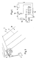
- The inventive awning will be disclosed in the following with the aid of particular embodiments in conjunction with the accompanying drawings. It is shown in:
- Fig. 1
- an inventive awning in a partial view from below;
- Fig. 2
- a roller arrangement with canopy in a partial view;
- Fig. 3
- the arrangement of a motor drive for the roller in a partial view;
- Fig. 4
- a pump schematic for pumping water for the cleaning device for cleaning the surface of the canopy;
- Fig. 5
- a schematic representation of two adjacently arranged awnings; and
- Fig. 6
- a schematic view of an arrangement having a common support structure with four awnings attached thereto, wherein the awnings can be extended to the right and/or the left of the central support and wherein the drawing shows all four awnings in their extended position.
- Fig.1 shows the inventive awning 1 in a partial view of the underside. The solar modules in form of
solar module strips 2 are flexible and mounted on a support so that the canopy can be easily rolled onto aroller 4. According to Fig.1, thesolar module strips 2 extend in the direction of movement (retraction and extansion) of the awning 1. However, an arrangement of thesolar modul strips 2 perpendicularly to the direction of movement is also possible. The adjacently positionedsolar modul strips 2 are connected to one another in a water-tight manner whereby the design of the seams 3 will be obvious to a person skilled in the art depending upon the material to be used. It is also possible to provide a detachable connection of thesolar module strips 2 to the support material in case that an exchange of thesolar module strips 2 should be necessary whenindividual strips 2 are damaged. Of course, if necessary, individualsolar module strips 2 can be replaced by support material, for example, when the damagedsolar module strip 2 cannot be replaced in a timely manner, in order to be able to still operate the awning 1. Although not apparent in the figure, thesolar module strips 2 are arranged with spacing therebetween so that the solar module strips alternate with canopy support material strips. The individual solar module strips may be attached to a support material and the resulting individual strips (support material strip and attached solar module strip) may then be connected to one another. - The canopy with the
solar module strips 2 that are connected to one another and the canopy support material strips are rolled up onto or rolled down from theroller 4 and are maintained in a stretched position by thejointed supports roller 4 provided with aneye 5 whereby the hooks of the crank will engage the eye 5 (see Fig.2) or can be achieved by an electric motor 6. The motor 6 is mounted within theroller 4 and can be operated by actuating a switch or by an electronic control unit, for example, with the aid of a timer 7 or according to certain weather-related parameters, such as sunlight intensity, humidity, temperature, wind, etc. (see Fig.3), measured by sensors connected to the control unit. - In order to protect the
solar module strips 2 against external influences, they may be provided, individually or the entire canopy surface, with a protective coating which will not inhibit the light transmission. The type of protective coating to be selected depends substantially on the required speciflcations and can be selected as desired. For example, a water-repellent coating can be provided or a wear-resistant coating or a soiling resistant coating etc. The wear-resistant coating, for example, will protect against wear resulting from cleaning by a brush or the friction caused upon retraction and extension of the canopy. A soiling resistant coating will reduce, due to its antistatic properties, adhesion of dirt particles. A protective layer against ice formation on the canopy is also possible. - In order to store the energy that is produced by the solar module strips 2, storage cells such as batteries are required which can be positioned within the
roller 4. A compact and self-contained awning is thus realized. For example, polypyrrole or lithium foil-based batteries having layers of the respective material can be used as electrode material, whereby the layers are embedded in gel. The batteries positioned within theroller 4 can be combined and connect to one another by current-conducting tracks which may have a plug-in device (electrical connector or socket) so that one is able to tap the energy stored in the batteries for eternal use. For example, it is possible to use the stored energy for a possible illumination of the free end of the awning canopy 1a that may have provided thereat an advertisement or company name on astrip 8. When the awning is connected to a building or house, the stored electrical energy can be used for garden maintenance (lawn mowers, trimmers, hedge clippers etc.) or for lighting at night for security reasons or illumination of advertisements or company name plates etc. - For cleaning the surface of the awning material 1a, it is possible to provide a
cleaning device 20 with brush at theawning cover 10 which must be supplied with water for the cleaning step. When the awning 1 is mounted at the wall of the building, the supply of tap water is easily realized, optionally by providing astorage container 17, so that it is possible to clean the surface of the canopy 1a by simply retracting or extending the canopy multiple times so that thecleaning device 20 with brush will act on the entire surface area of the canopy. However, when the supply of tap water is difficult to realize, a sufficientlylarge storage container 17 for cleaning water must be provided. Whether sufficient space is available in the interior of theroller 4 for such acontainer 17 depends on the size of the awning. However, sufficient space will be available in thehollow supports container 17 at the exterior side of thesupports device 14 at the free end of the awning material 1 a opposite theroller 4, for example, a rain gutter-type arrangement, which may collect, in addition to the rain water or melting snow, the water dispensed by thecleaning device 20. The water collected in the collectingdevice 14 is pumped by apump 15 through a coarse and afine filter 16 and is then directly supplied to thecleaning device 20 for further use, i.e., it is used to refill thewater reservoir 17. Shut-offvalves 18 are provided that are automatically operated and prevent overfilling of thereservoir 17. A water overflow may be provided at the collecting device14. - As mentioned above, the inventive awning 1 not only can be used as protection against sun radiation and against precipitation, but can also be used, because of the presence of the solar module strips 2, to provide electrical energy derived from the sunlight. The efficiency of the solar modules depends on the intensity of the sunlight. Additional solar modules may be attached to the underside of the canopy in order to produce additional energy. This means that during the day the effect of the sun radiation will provide the greatest possible energy efficiency while at night the conversion to useful energy is practically zero. However, in cases where strong illumination devices are present in the adjacent areas, for example, in sports stadiums etc, it is possible to use the light radiation from the strong illumination devices which are used for illumination of only a certain area, but will emit horizontally propagated light rays so that the surrounding areas are also illuminated. When these light rays impinge on the solar modules of the inventive awning, they can also be converted into electrical energy. Even though the energy yield may be low, an additional energy source is thus provided for the already present solar modules. Thus, an additional source of energy conversion is realized which otherwise would not be possible at night.
- For this particular use, it is best to extend the canopy from the
roller 4 such that it is positioned perpendicularly downwardly relative to the roller. For this purpose, thesupports pneumatic device 19 that bridges the joint 12c of the two arms of thesupports supports roller 4 that allows a downward positioning of thesupports supports supports joints 12c, the canopy, when extended and pivoted at thejoints 12c, is positioned substantially at a right angle (or any other suitable angle, preferably greater than a right angle) with approximately half its surface area in a downward position. Either the entire canopy surface area or the forward half that is folded down is thus exposed to the light rays coming from the illumination devices operating at night. The light received from the illumination devices can thus be converted into energy. As a further advantage, it should be noted that the folded arrangement, i.e., forward canopy half is folded down, also provides wind protection for persons seated under the awning. - The folding mechanism, i.e., folding the awning at approximately half its length downwardly, can also be used during the day to provide extra protection from the elements, e.g., the sun, wind, rain. A pivotable holder, when adjustable over the pivot range, can also be used to vary the angle at which the awning is positioned relative to the sun.
- The batteries (storage cells) are preferably mounted within the
roller 4 for storing energy produced by the solar module strips mounted on the support material. This self-contained awning can be detached from the building or vehicle and stored away or mounted at a different location. This is especially advantageous in connection with vehicles and trailers. - Since the energy storage in a battery and also the use of energy stored in batteries results in heat being produced due to the chemical processes occurring, it is necessary to remove excess heat from the arrangement.
- This can be solved in multiple ways.
- When the batteries are positioned in the
roller 4 that is provided for retracting and storing as well as extending the canopy, the heat dissipation caused by natural events such as airflow (wind) is often insufficient, especially since theroller 4 is usually mounted at a protected location along the wall of a building or a vehicle so that air flow only will pass along a portion of theroller 4. This cannot be sufficiently improved by providing theroller 4 with a fan, especially since such a fan would also require energy, and because the air flow produced by the fan only has a minimal reach. A separate tube as a housing for receiving the batteries may be mounted at the free end of the canopy. This would provide sufficient natural air flow about the entire circumference of the tube and the entire length of the tube so that, by doing so, the heat dissipation would be considerably improved without increasing cost of electrical cable connections to the batteries or storage cells by a considerable amount. Furthermore, the space that is then available within theroller 4 could be used for mounting therein other devices or reservoirs as disclosed above. - Another possibility of heat dissipation is the use of a cooling liquid know in various forms and preferably in the form of water. Since the amount of heat energy to be dissipated is relatively small, the required components such as cooling tubes, heat exchanger, pump, are all small and can be easily installed, for example, at the wall to which the awning is connected or at one of the
supports - A possibility for energy storage is also the use of highly efficient capacitors (for example, electric double layer capacitors available from Panasonic), especially when made of environmentally safe materials, that are to be used instead of batteries because in this manner no chemical reactions take place and no heat is produced. The installation of such highly efficient capacitors depends on whether their construction allows a rotary movement about their axis (when mounted in the roller) whithout their efficiency being negatively effected by rotation whithin the roller. When this is the case, it is possible to arrange them whithin the
roller 4. In other cases, highly efficient capacitors are stationarily mounted, for example, in one of thesupports - The energy stored within the batteries, accumulators, or the highly efficient capacitors can be used for operating different electrical consumers depending on the specific needs of the customer. For example, the energy can be used in connection with functions relating to the awning itself, for example, the retraction or extension of the awning from the roller, which may be controlled so as to be performed by a control unit based on a timer or sensors measuring various parameters such as temperature, humidity, sunlight intensity etc. It is expedient to perform certain operations as a function of time and/or environmental influences, for example, by arranging certain sensors cooperating with an electronic control unit that will provide a controlling function according to preset parameter limits. The artisan will be able to determine easily which range and magnitude the respective parameter limits should have and how to connect these senors most effectively.
- The stored energy can also be used for operating the cleaning devices of the canopy and/or for water storage (collecting rain water and melted snow and pumping the water into the reservoir of the cleaning device).
- The energy balance of the inventive awning can further be improved by solar modules mounted on the underside of the canopy so that the additional solar modules can collect and convert reflected sunlight .
- The inventive awning can be used on houses with curved roof structures or at bus stop shelters with curved roots, for example, also connection with greenhouses, pavilions, and similar structures. The awning can be adapted to various types of roof structures having a concave or convex curvature. The energy stored in the storage cells can be used, for example, for operating a climate control unit in the greenhouse. In these embodiments, the frame of the awning can be a component of the constructive parts of the bus stop shelter or the greenhouse.
- Since the canopy can provide both a roof as well as a sun protection means, it is possible to save material and thus produce the buildings more cheaply. The awning (comprised of the canopy and the awning frame) is matched to the curvature of the roof structure. The canopy having solar modul strips or support material having solar modul strips mounted thereon can also be suspended from cables with which the awning is then pulled into position. The awning can be manually manipulated or can be moved by a respective motor.
- The energy storage means, motors and other electrical devices can be mounted within the hollow space of the components of the structure to which the awning is to be connected.
- According to another embodiment, it is possible to connect a plurality of awnings 1a, 1b (Fig.5) or 1c, 1d, 1e, 1f (Fig.6) to one another. A common support structure may be provided. It is especially advantageous when
such awnings 1c, 1 d, 1e, 1f can be extended from the central support structure (not shown) to both sides (in opposite directions) so that a substantially free standing large surface area awning is provided (see Fig. 6, showing awnings 1c, 1d on one side of the common support structure andawnings 1e, 1f extending on the other side from the common support structure in the opposite direction). As shown in Fig. 6, the awnings can extend at different angles, depending on the position of the sun. All of the awnings may be connected to a central control unit and may have a common central storage cell. - For large buildings (high rise buildings, office buildings, large hotel complexes etc) that have multiple awnings in various locations it may be expedient to have all awnings connected to a central control station that may monitor, in addition to controlling the operation of the awnings (extension, retraction, angle adjustment, cleaning, etc), also the proper function of the solar modules in order to indicate at the central station when a solar module is defective and needs replacement. Also, other malfunctions may also be reported electronically to the central control station so that repair and maintenance personnel can be sent out immediately. Such a central monitoring station can also be operated remote by the contractor who installed the awnings and who offers a service and maintenance contract. To a person skilled in the art, various control and monitoring devices, including computers and sensors, for such a purpose are known and will therefore not be discussed in detail in this context.
- Institutions and businesses such as banks have bullet proof glass in their windows in order to provide extra protection. The awning material can also be embodied in a bullet-proof manner and can also be designed such that temperature fluctuations can be compensated. Bullet proof embodiment of the awning material can be realized by providing various layers of Kevlar fabric.
- Temperature fluctuation can be compensated by integrating foamed materials and/or integrated paraffins. Such an embodiment retains more heat energy so that people can sit comfortably under the awnings even at night. The preferred size of the inventive awnings is 3 to 4 meters. However, larger or smaller size awnings are also possible.
- It is also possible to provide a substantially vertically suspended protective sheet at the awning as a lateral protection.
- The visual impression of people sitting under or behind the awning can be improved by providing light-reflecting mirrors at the awning.
- However, awning fabric (canopy materials) are known which change according to the exterior light conditions and thus provide a uniform lighting within the space that is covered by the awning.
- A further improvement of the awning would be to have a transparent solar module that allows light to pass through so that the space under the awning is not too dark and still illuminated sufficiently. This is also important when the awning is used as an individual vertical window or glass door shade, for example.
- The present invention is, of course, in no way restricted to the specific disclosure of the specification and drawings, but also encompasses any modifications within the scope of the appended claims.
Claims (20)
- An awning comprising;
a frame;
a flexible canopy (1a) mounted to said frame so as to be retractable into a retracted position and extendable into an extended position;
said canopy (1a) having an upper side and an underside;
said canopy(1a) comprising at least one flexible solar module (2) on said upper side;
said frame comprising a roller (4) onto which said canopy (1a) is rolled in said retracted state;
at least one storage cell storing electrical energy produced by said at least one solar module (2), said at least one storage cell being connected to said at least one solar module characterised in that said at least one storage cell is mounted in said roller;
and in that said solar modules are solar module strips (2),;
a strip of support material being located between neighbouring solar module strips (2), said support material being light-collecting material which transmits collected light to said solar module strips (2). - An awning according to claim 1, characterized by a motor (6) mounted inside said roller and connected to said at least one storage cell, wherein said motor (6) is supplied with electrical energy by said at least one storage cell for rotating said roller (4) in order to extend and retract said canopy (1a).
- An awning according to claim 1, characterized by an electrical connector to connect an external electrical consumer to said at least one storage cell .
- An awning according to claim 1, characterised by a cleaning device (20) for cleaning said canopy.
- An awning according to claim 4, characterized in that said cleaning device (20) comprises a cleaning liquid reservoir (17) mounted inside said roller (4) or inside frame portions of a frame.
- An awning according to claim 5, characterized by a collecting device (14) for collecting precipitation and guiding the collected precipitation into said cleaning liquid reservoir (17), wherein said collecting device (14) is connected to a forward end of said canopy (1a) remote from said roller (4) in said extended position.
- An awning according to claim 6, characterized by a pump (15) for pumping the collected precipitation to said cleaning device (20), wherein a shutoff valve (18) is provided for controlling flow to said cleaning liquid reservoir.
- An awning according to claim 7, characterized by a coarse and a fine filter (16) mounted between said collecting device (14) and said cleaning device (20) for filtering the collected precipitation.
- An awning according to claim 5,wherein said cleaning device (20) further comprises a pump (15) pumping the cleaning liquid onto the surface of that canopy (1a).
- An awning according to claim 4, characterized by a cover covering said canopy in said retracted state, wherein said cleaning device (20) is mounted in that cover (10).
- An awning according to claim 4, wherein said cleaning device (20) has at least one cleaning brush.
- An awning according to claim 1, wherein said solar modules of the solar module strips (2) comprise a protective coating that does not impede energy transmission to said solar modules.
- An awning according to claim 12,wherein said protective coating reduces frictional wear and in water-repellant and/or is soil repellant that does not impede energy transmission to said solar modules.
- An awning according to claim 1, wherein said frame comprises supports (12a,12b) for streching said canopy (1a) wherein each one of said supports (12a,12b) has a joint (12c) and a looking device (19) for bridging said joint (12c) that when activated (1a), direct said canopy (1a) downwardly when extended.
- An awning according to claim 1, wherein said at least one storage cell is mounted so as to be exposed to an air current for heat dissipation.
- An awning according to claim 1,further comprising a cooling device with circulating cooling liquid for dissipating heat of said at least one storage cell.
- An awning according to claim 16, wherein said cooling device comprise components for recirculating the cooling liquid and wherein said components are mounted at least partially on parts of said frame (12a, 12b) or mounted at least partially on parts of said frame (12a, 12b) or mounted at least partially external to said awning.
- An awning according to claim 1,wherein said at least one storage cell is a highly efficient capacitor comprised of environmentally friendly materials.
- An awning according to claim 1, wherein said frame(12a, 12b) comprises a tubular member connected to an end of said canopy (1a) remote from said roller(4), wherein said at least one storage cell is mounted in said tubular member.
- An awning according to claim 1,wherein said canopy (1a) comprises additional solar modules or solar module strips (2) on said underside.
Applications Claiming Priority (9)
| Application Number | Priority Date | Filing Date | Title |
|---|---|---|---|
| DE19823902 | 1998-05-28 | ||
| DE19823902 | 1998-05-28 | ||
| DE19825017 | 1998-06-04 | ||
| DE19825017A DE19825017C1 (en) | 1998-05-28 | 1998-06-04 | Removable blind or awning with solar modules and batteries for storing energy |
| DE19844920 | 1998-09-30 | ||
| DE19844920A DE19844920C1 (en) | 1998-06-04 | 1998-09-30 | Flexible type protective awning used in building, vehicle |
| DE19915169 | 1999-04-01 | ||
| DE19915169 | 1999-04-01 | ||
| PCT/EP1999/003645 WO1999061721A2 (en) | 1998-05-28 | 1999-05-26 | Awning with flexible solar modules |
Publications (2)
| Publication Number | Publication Date |
|---|---|
| EP1082502A2 EP1082502A2 (en) | 2001-03-14 |
| EP1082502B1 true EP1082502B1 (en) | 2005-02-02 |
Family
ID=27438811
Family Applications (1)
| Application Number | Title | Priority Date | Filing Date |
|---|---|---|---|
| EP99926431A Expired - Lifetime EP1082502B1 (en) | 1998-05-28 | 1999-05-26 | Awning with flexible solar modules |
Country Status (5)
| Country | Link |
|---|---|
| EP (1) | EP1082502B1 (en) |
| AT (1) | ATE288526T1 (en) |
| AU (1) | AU4369399A (en) |
| CA (1) | CA2333458A1 (en) |
| WO (1) | WO1999061721A2 (en) |
Cited By (3)
| Publication number | Priority date | Publication date | Assignee | Title |
|---|---|---|---|---|
| EP2423977A1 (en) * | 2010-08-31 | 2012-02-29 | Solarkey S.r.l. | Photovoltaic panel for greenhouses and greenhouse photovoltaic covering structure comprising the panel |
| WO2022020217A1 (en) | 2020-07-18 | 2022-01-27 | EvoluSun Inc. | Energy generating photovoltaic awning with scissor mechanism and tilting photovoltaic panels |
| DE102020133068B3 (en) | 2020-12-11 | 2022-05-19 | Audi Aktiengesellschaft | Textile structure with flexible solar cells |
Families Citing this family (16)
| Publication number | Priority date | Publication date | Assignee | Title |
|---|---|---|---|---|
| DE19932731A1 (en) * | 1999-07-14 | 2001-03-22 | Warema Renkhoff Gmbh & Co Kg | Sun protection system with curtain adjustment that adapts to the incidence of light |
| AU778068B2 (en) | 2000-01-31 | 2004-11-11 | Turnils A.B. | Awning assembly and control system |
| US6525263B2 (en) * | 2000-04-12 | 2003-02-25 | Mueller Hermann-Frank | Awning |
| FI4918U1 (en) * | 2001-02-20 | 2001-05-16 | Simo Jaervinen | Solstrålningsskydd |
| FR2823527B1 (en) * | 2001-04-17 | 2003-12-12 | Jacques Lambey | PHOTOGENERATIVE CANVAS FOR AWNINGS AND POOL COVERS |
| FR2880371A1 (en) * | 2005-01-04 | 2006-07-07 | Jacques Lambey | Blind or awning photo-generator for converting solar energy into electrical energy, has units arranged under form of flexible sheet or bar arrangement, where one unit is superimposed on another unit at certain distance when they unfolded |
| WO2007003144A1 (en) * | 2005-06-30 | 2007-01-11 | Gerd Lukoschus | Heatable awning |
| US8316910B2 (en) | 2005-08-26 | 2012-11-27 | Dometic Llc | Awning assemblies |
| DE102007013180A1 (en) * | 2007-03-20 | 2008-09-25 | Schmitz-Werke Gmbh + Co. Kg | awning |
| GB2457255A (en) * | 2008-02-07 | 2009-08-12 | Amperor | Canopy or blind with solar panel |
| ITGE20100142A1 (en) * | 2010-12-24 | 2012-06-25 | Giacomo Carcangiu | INNOVATIONS IN PHOTOVOLTAIC AND SIMILAR SOLAR MODULES |
| KR101194197B1 (en) * | 2012-06-21 | 2012-10-25 | 서울과학기술대학교 산학협력단 | Canopy type photovoltaic system |
| EP2743442B1 (en) * | 2012-12-12 | 2016-04-27 | FAKRO PP Spolka z ograniczona odpowiedzialnoscia | Automatic roller blind for roof windows and a method of controlling thereof |
| DE102013108013B4 (en) * | 2013-07-26 | 2017-12-14 | Heliatek Gmbh | Device for protecting and cleaning optoelectronic components |
| US10560050B2 (en) | 2018-06-15 | 2020-02-11 | Evolusun, Inc. | Innovative energy generating photovoltaic awning |
| US20240097612A1 (en) * | 2022-09-21 | 2024-03-21 | The Regents Of The University Of Michigan | Organic optoelectronic device and method |
Family Cites Families (17)
| Publication number | Priority date | Publication date | Assignee | Title |
|---|---|---|---|---|
| FR2017500A1 (en) * | 1968-09-06 | 1970-05-22 | Westinghouse Electric Corp | Flexible solar cell panel |
| DE2836938A1 (en) * | 1978-08-24 | 1980-03-06 | August Prof Dipl Phys D Winsel | Electrically powered roller shutter or blind - has geared motor and accumulators housed in cylindrical rotary unit |
| FR2481355A1 (en) * | 1980-04-29 | 1981-10-30 | Franciaflex | MOTORIZED ARM TYPE BANK STORAGE |
| DE3302934A1 (en) * | 1983-01-28 | 1984-08-02 | Hans Georg 8000 München März | Solar generator |
| DE3427574A1 (en) * | 1984-07-26 | 1986-02-06 | Stromeyer Ingenieurbau GmbH, 7750 Konstanz | DEVICE FOR SHADING SURFACES |
| EP0351459A1 (en) * | 1988-07-18 | 1990-01-24 | Masayoshi Fukushi | Sub-awning sheet support assembly |
| DE3832688A1 (en) | 1988-09-27 | 1990-04-05 | Edu Hundt & Co | Awning with solar cells |
| DE3909937C2 (en) * | 1989-03-25 | 1994-05-11 | Man Nutzfahrzeuge Gmbh | Electrically movable awning for a passenger transport vehicle, especially a bus |
| DE4003399A1 (en) | 1990-02-05 | 1991-08-08 | Mueller Hermann Frank | Vehicular sun visor with battery-charging solar cells - on outward faces of visor and supplementary panel which can be detached for use outside vehicle |
| DE4031471C2 (en) * | 1990-10-05 | 1994-01-27 | Stahl Systemtechnik Gmbh | Awning protection roof |
| CH684426A5 (en) * | 1992-01-21 | 1994-09-15 | Walser & Co Ag | Motorized operating system for roll or movable shading, weather protection or security systems for buildings. |
| DE4318437A1 (en) * | 1993-06-03 | 1994-12-08 | Rau Metall Gmbh & Co | Awning with a support profile |
| US5433259A (en) | 1993-11-22 | 1995-07-18 | Carefree/Scott Fetzer Company | Retractable awning with integrated solar cells |
| FR2742002B1 (en) * | 1995-11-30 | 1998-02-20 | Peugeot | ELECTRIC ACCUMULATOR BATTERY PROVIDED WITH COOLING MEANS |
| DE19620619A1 (en) | 1996-05-22 | 1997-11-27 | Alexander Ing Grad Solmos | Automatic operation of outside sun blind for roof windows |
| DE19627394C2 (en) * | 1996-07-06 | 1998-12-17 | Werner Dipl Ing Dietzsch | Cleaning device for awnings |
| DE19731853A1 (en) * | 1997-07-24 | 1999-03-04 | Kti Kirstein Ges Fuer Innovati | Solar cell unit |
-
1999
- 1999-05-26 AT AT99926431T patent/ATE288526T1/en not_active IP Right Cessation
- 1999-05-26 EP EP99926431A patent/EP1082502B1/en not_active Expired - Lifetime
- 1999-05-26 CA CA002333458A patent/CA2333458A1/en not_active Abandoned
- 1999-05-26 WO PCT/EP1999/003645 patent/WO1999061721A2/en not_active Ceased
- 1999-05-26 AU AU43693/99A patent/AU4369399A/en not_active Abandoned
Cited By (4)
| Publication number | Priority date | Publication date | Assignee | Title |
|---|---|---|---|---|
| EP2423977A1 (en) * | 2010-08-31 | 2012-02-29 | Solarkey S.r.l. | Photovoltaic panel for greenhouses and greenhouse photovoltaic covering structure comprising the panel |
| WO2022020217A1 (en) | 2020-07-18 | 2022-01-27 | EvoluSun Inc. | Energy generating photovoltaic awning with scissor mechanism and tilting photovoltaic panels |
| DE102020133068B3 (en) | 2020-12-11 | 2022-05-19 | Audi Aktiengesellschaft | Textile structure with flexible solar cells |
| WO2022122227A1 (en) | 2020-12-11 | 2022-06-16 | Audi Ag | Fabric structure comprising flexible solar cells |
Also Published As
| Publication number | Publication date |
|---|---|
| CA2333458A1 (en) | 1999-12-02 |
| WO1999061721A2 (en) | 1999-12-02 |
| WO1999061721A3 (en) | 2000-02-24 |
| ATE288526T1 (en) | 2005-02-15 |
| EP1082502A2 (en) | 2001-03-14 |
| AU4369399A (en) | 1999-12-13 |
Similar Documents
| Publication | Publication Date | Title |
|---|---|---|
| AU4369399A (en) | Awning with flexible solar modules | |
| US6812397B2 (en) | Photocurrent-generating fabric and support for such a fabric | |
| FR2913101A1 (en) | Direct/indirect fluid i.e. water, heating device for e.g. producing sanitary hot water in building, has sunshade regulating fluid temperature and covering part to avoid exposure to sun to reduce fluid overheating, in deployed position | |
| KR102264333B1 (en) | Safety railing device | |
| US20240011317A1 (en) | Novel shading system | |
| KR20110011152A (en) | Sunshade system that controls the concentration of sunlight and the inflow of sunlight | |
| US20220329203A1 (en) | Low-Profile Solar Panel (LPSP) for Vertical, Sloped, and Horizontal Installations with Convertible Multifunctionality and Appearance Adaptation | |
| KR102732067B1 (en) | Solar cell module frame with electrical wiring inside the frame for easy tracking of sunlight | |
| KR102214382B1 (en) | Multifunctional Structure having independent electric power system | |
| CN105317241A (en) | Solar energy sentry box system | |
| AU2003262435B2 (en) | Awning with flexible solar modules | |
| CN105317244A (en) | Temperature regulating type solar sentry box | |
| AU2021202734A1 (en) | Solar Shutters Modular Unit | |
| KR101243383B1 (en) | double window with photovoltaic power generation | |
| KR20210074822A (en) | Mobile selling booth have solar energy generation function | |
| CN215977719U (en) | Energy-saving prefabricated building | |
| KR20200067688A (en) | A solar power generation system with automatic folding function according to air volume | |
| KR102902056B1 (en) | Smart shade device | |
| KR20220105267A (en) | Multifunctional Structure having independent electric power system | |
| KR100290228B1 (en) | Solar heating system with adjustable heat flow direction and solar heat collection | |
| KR102912620B1 (en) | A mobile solar home control system based on solar modules | |
| DE202020100122U1 (en) | Energy shell and building equipped with it | |
| CN217269739U (en) | Sun-shading window | |
| CN215978627U (en) | Energy-concerving and environment-protective type bus shelter | |
| US20250134224A1 (en) | Protection device such as a parasol and a set of such devices connected to one another |
Legal Events
| Date | Code | Title | Description |
|---|---|---|---|
| PUAI | Public reference made under article 153(3) epc to a published international application that has entered the european phase |
Free format text: ORIGINAL CODE: 0009012 |
|
| 17P | Request for examination filed |
Effective date: 20001222 |
|
| AK | Designated contracting states |
Kind code of ref document: A2 Designated state(s): AT BE CH DK ES FR GB GR IT LI NL PT SE |
|
| 17Q | First examination report despatched |
Effective date: 20010709 |
|
| GRAP | Despatch of communication of intention to grant a patent |
Free format text: ORIGINAL CODE: EPIDOSNIGR1 |
|
| GRAS | Grant fee paid |
Free format text: ORIGINAL CODE: EPIDOSNIGR3 |
|
| GRAA | (expected) grant |
Free format text: ORIGINAL CODE: 0009210 |
|
| AK | Designated contracting states |
Kind code of ref document: B1 Designated state(s): AT BE CH DK ES FR GB GR IT LI NL PT SE |
|
| PG25 | Lapsed in a contracting state [announced via postgrant information from national office to epo] |
Ref country code: NL Free format text: LAPSE BECAUSE OF FAILURE TO SUBMIT A TRANSLATION OF THE DESCRIPTION OR TO PAY THE FEE WITHIN THE PRESCRIBED TIME-LIMIT Effective date: 20050202 Ref country code: IT Free format text: LAPSE BECAUSE OF FAILURE TO SUBMIT A TRANSLATION OF THE DESCRIPTION OR TO PAY THE FEE WITHIN THE PRESCRIBED TIME-LIMIT;WARNING: LAPSES OF ITALIAN PATENTS WITH EFFECTIVE DATE BEFORE 2007 MAY HAVE OCCURRED AT ANY TIME BEFORE 2007. THE CORRECT EFFECTIVE DATE MAY BE DIFFERENT FROM THE ONE RECORDED. Effective date: 20050202 Ref country code: ES Free format text: LAPSE BECAUSE OF FAILURE TO SUBMIT A TRANSLATION OF THE DESCRIPTION OR TO PAY THE FEE WITHIN THE PRESCRIBED TIME-LIMIT Effective date: 20050202 Ref country code: BE Free format text: LAPSE BECAUSE OF FAILURE TO SUBMIT A TRANSLATION OF THE DESCRIPTION OR TO PAY THE FEE WITHIN THE PRESCRIBED TIME-LIMIT Effective date: 20050202 Ref country code: AT Free format text: LAPSE BECAUSE OF FAILURE TO SUBMIT A TRANSLATION OF THE DESCRIPTION OR TO PAY THE FEE WITHIN THE PRESCRIBED TIME-LIMIT Effective date: 20050202 |
|
| REG | Reference to a national code |
Ref country code: GB Ref legal event code: FG4D |
|
| REG | Reference to a national code |
Ref country code: CH Ref legal event code: EP |
|
| PG25 | Lapsed in a contracting state [announced via postgrant information from national office to epo] |
Ref country code: SE Free format text: LAPSE BECAUSE OF FAILURE TO SUBMIT A TRANSLATION OF THE DESCRIPTION OR TO PAY THE FEE WITHIN THE PRESCRIBED TIME-LIMIT Effective date: 20050502 Ref country code: GR Free format text: LAPSE BECAUSE OF FAILURE TO SUBMIT A TRANSLATION OF THE DESCRIPTION OR TO PAY THE FEE WITHIN THE PRESCRIBED TIME-LIMIT Effective date: 20050502 Ref country code: DK Free format text: LAPSE BECAUSE OF FAILURE TO SUBMIT A TRANSLATION OF THE DESCRIPTION OR TO PAY THE FEE WITHIN THE PRESCRIBED TIME-LIMIT Effective date: 20050502 |
|
| NLV1 | Nl: lapsed or annulled due to failure to fulfill the requirements of art. 29p and 29m of the patents act | ||
| PLBE | No opposition filed within time limit |
Free format text: ORIGINAL CODE: 0009261 |
|
| STAA | Information on the status of an ep patent application or granted ep patent |
Free format text: STATUS: NO OPPOSITION FILED WITHIN TIME LIMIT |
|
| 26N | No opposition filed |
Effective date: 20051103 |
|
| ET | Fr: translation filed | ||
| PGFP | Annual fee paid to national office [announced via postgrant information from national office to epo] |
Ref country code: GB Payment date: 20070627 Year of fee payment: 9 Ref country code: CH Payment date: 20070821 Year of fee payment: 9 |
|
| PG25 | Lapsed in a contracting state [announced via postgrant information from national office to epo] |
Ref country code: PT Free format text: LAPSE BECAUSE OF NON-PAYMENT OF DUE FEES Effective date: 20050702 |
|
| REG | Reference to a national code |
Ref country code: CH Ref legal event code: PL |
|
| GBPC | Gb: european patent ceased through non-payment of renewal fee |
Effective date: 20080526 |
|
| PG25 | Lapsed in a contracting state [announced via postgrant information from national office to epo] |
Ref country code: LI Free format text: LAPSE BECAUSE OF NON-PAYMENT OF DUE FEES Effective date: 20080531 Ref country code: CH Free format text: LAPSE BECAUSE OF NON-PAYMENT OF DUE FEES Effective date: 20080531 |
|
| PGFP | Annual fee paid to national office [announced via postgrant information from national office to epo] |
Ref country code: FR Payment date: 20081126 Year of fee payment: 11 |
|
| PG25 | Lapsed in a contracting state [announced via postgrant information from national office to epo] |
Ref country code: GB Free format text: LAPSE BECAUSE OF NON-PAYMENT OF DUE FEES Effective date: 20080526 |
|
| REG | Reference to a national code |
Ref country code: FR Ref legal event code: ST Effective date: 20110131 |
|
| PG25 | Lapsed in a contracting state [announced via postgrant information from national office to epo] |
Ref country code: FR Free format text: LAPSE BECAUSE OF NON-PAYMENT OF DUE FEES Effective date: 20100531 |