EP1081981B1 - Dynamische Veränderung der Datenrate - Google Patents
Dynamische Veränderung der Datenrate Download PDFInfo
- Publication number
- EP1081981B1 EP1081981B1 EP99907950A EP99907950A EP1081981B1 EP 1081981 B1 EP1081981 B1 EP 1081981B1 EP 99907950 A EP99907950 A EP 99907950A EP 99907950 A EP99907950 A EP 99907950A EP 1081981 B1 EP1081981 B1 EP 1081981B1
- Authority
- EP
- European Patent Office
- Prior art keywords
- time slot
- change
- base station
- transmission rate
- subscriber station
- Prior art date
- Legal status (The legal status is an assumption and is not a legal conclusion. Google has not performed a legal analysis and makes no representation as to the accuracy of the status listed.)
- Expired - Lifetime
Links
Images


Classifications
-
- H—ELECTRICITY
- H04—ELECTRIC COMMUNICATION TECHNIQUE
- H04W—WIRELESS COMMUNICATION NETWORKS
- H04W36/00—Hand-off or reselection arrangements
- H04W36/06—Reselecting a communication resource in the serving access point
Definitions
- the present invention relates to a mobile communication system which permits independent setting of the transmission rates of up- and down-links.
- Mobile communication systems have a structure in which subscriber stations, i.e. mobile stations (such as mobile vehicle-installed communication devices and mobile portable communication devices) are connected to a base station via radio channels.
- subscriber stations i.e. mobile stations (such as mobile vehicle-installed communication devices and mobile portable communication devices) are connected to a base station via radio channels.
- frequency sharing radio frequency spectra
- time slot sharing mobile communication system which shares a TDMA signal and a time division CDMA signal in the same time slot is disclosed in our U.S. Patent No. 5,805,581 (Japanese Pat. Appln. Laid-Open Gazette No. 8-130766 , EP701337A ).
- the channel capacity of an up-link over which the subscriber station sends data to the base station and the channel capacity of a down-link over which the base station sends data to the subscriber station be set independently of each other.
- the subscriber station upon occurrence of a situation in which a momentary increase takes place in the amount of data to be sent from the subscriber station to the base station, the subscriber station computes the transmission rate required taking into consideration the amount of increase in the data to be sent, and sends a request for a change of the transmission rate to the base station.
- the base station Upon receiving the request for a change of the transmission rate from the subscriber station, the base station determines whether a change of the transmission rate can be accepted after hunting for an idle channel in the link over which they are currently in communication with each other.
- the base station when judging that a change of the transmission rate can be accepted, the base station sends to the subscriber station the identification number of the communication channel to be used thereafter.
- the subscriber station Upon receiving from the base station the identification number of the communication channel for subsequent use from the base station after sending thereto the request for a change of the transmission rate, the subscriber station sends data over the designated communication channel to the base station after that.
- the transmission rate can be changed when permission is obtained from the distant station after sending thereto a request for a change of the transmission rate, but a considerable amount of time is needed until the transmission rate is actually changed; hence, when the amount of data to be sent varies greatly, congestion of data or the like occurs, giving rise to a problem that the immediacy of data sent in real time is impaired.
- the present invention is intended to solve such a problem as mentioned above and has for its object to provide a mobile communication system which enables the data transmission rate to be changed quickly during communication.
- Document EP 0 782 297 is considered as the closest prior art, and discloses a method and communication apparatus according to the preambles of claims 1, 10, 19 and 20.
- the present invention provides a method in accordance with independent claims 1 and 10, as well as a base station in accordance with independent claim 19 and a communication system in accordance with independent claim 20. Further preferred embodiments are given in the dependent claims.
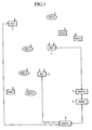
- Fig. 1 is a diagram illustrating the general outline of a mobile communication system according to Embodiment 1 of the present invention, which reference numerals 1 to 3 denote base stations, 4 a mobile switching center for controlling the base stations 1 and 3, 5 a mobile switching center for controlling the base station 2, and 6 PSTN (Public Switching Telephone Network) which is a public system to which the mobile switching centers 4 and 5 are wire-connected.
- PSTN Public Switching Telephone Network
- Reference characters MS11 to MS14 denote mobile stations which are radio-connected to any one of the base stations 1 to 3, such as mobile vehicle-installed communication devices or mobile/portable communication devices, and WS21 to WS23 denote half-fixed or fixed FWA (Fixed Wireless Access) stations which are radio-connected to any one of the base stations 1 to 3.
- FWA Wireless Wireless Access
- the mobile stations and the FWA stations carry out radio communications with any one of the base stations 1 to 3 over a low-speed TDMA data channel, a medium-/high-speed TDMA data channel, a time division CDMA channel and so forth, but they have a channel for carrying out voice or low-speed data communication other than the above-mentioned channels.
- the mobile stations and the FWA stations will hereinafter be collectively called subscriber stations.
- the mobile switching centers 4 and 5 are wire-connected to the PSTN 6, interfaces of the base stations 1 to 3 with the mobile switching centers 4 and 5, the mobile switching centers 4 and 5 and the PSTN 6 have communication capabilities in an ATM (Asynchronous Transfer Mode) as well as in an ordinary communication mode, and they will be described to carry out ATM communications.
- ATM Asynchronous Transfer Mode
- the subscriber stations MS11 to MS14 and the WS21 to WS23 and the base stations exchange signals through the use of a digital modulation system; let it be assumed that they are radio-linked, for example, ) by an FDMA/TDD (Time Division Duplex) system which is a frequency division multiple access/time division two-way communication system, CDMA/TDD (Code division Multiple Access/Time Division Duplex) system which is a code division multiple access/time division two-way communication system, TDMA/FDD (Multi-carriers Time division Multiple Access/Frequency Division Duplex) system which is a code division multi-carrier time division/frequency division two-way communication system, TDMA/TDD system, time division CDMA/FDD system, or time division CDMA/TDD system.
- FDMA/TDD Time Division Duplex
- CDMA/TDD Code division Multiple Access/Time Division Duplex
- TDMA/FDD Multi-carriers Time division Multiple Access/Frequency Division Duplex
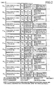
- Fig. 2 is an explanatory diagram depicting examples of time slots for TDMA and time division CDMA PCS (Personal Communication System) and for a cellular system; in Fig. 2 , #31-0A to 3A are time division CDMA time slots for a PCS high-speed data transmission downlink in a first frame, and #31-0B to 3B are time division CDMA time slots for in the first frame.
- TDMA Time Division Multiple Access
- PCS Personal Communication System
- #32-0A to #32-3B are time division CDMA time slots for PCS low-speed data transmission in the first frame; #33-1A to #33-2B and #35-1A to #35-2B are TDMA time slots for PCS low-speed data transmission in the first frame; and #34-0A to #34-3B are TDMA time slots for PCS medium-speed data transmission in the first frame.
- #36-1A to #35-2B are TDMA time slots for PCS high-speed data transmission in the first frame;
- #35-0A to #35-3B are TDMA time slots for cellular low-speed data transmission in the first frame;
- #37-0A to #37-3B are time division CDMA time slots for cellular high-speed data transmission in the first and second frames.
- Fig. 2 shows Up-Link and Down-Link of the TDD (Time Division Duplex) system, the Up-Link being time slots expressed by R1 0B to R1 3B on the time axis and the Down-Link time slots expressed by T1 0A to T1 3A ) and T2 0A to T2 3A on the time axis.
- the time slots R10B to R13B of UP-Link and the time slots T1 0A to T1 3A of Down-Link constitute one frame, and time slots T2 0A to T2 3A are those belonging to the next frame. That is, Fig. 2 expresses one and a half frame.
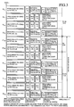
- Fig. 3 is an explanatory diagram showing other examples of TDMA and time division CDMA time slots for PCS and cellular system use; the time slots of the same names as those in Fig. 2 are identical with those in the latter, and hence no description will be repeated.
- #31-4A to #31-5A are asymmetrical portions of Down-Link in time division CDMA time slots for PCS high-speed data transmission in the first frame, which are time slots to be used when the amount of information to be sent from the base station to the subscriber station is larger than the amount of information to be sent from the subscriber station to the base station.
- #31-0B to #31-1B are time slots of UP-Link in the first frame. That is, all time slots contained in those T10A to T15A are time slots in the first and other frames which belong to Down-Link. Similarly, all time slots contained in R10B to R11B are time slots in the first and other frames which belong to Up-Link.
- Fig. 3 shows the case of an asymmetrical TDD system in which the transmission timing of Up-Link and the transmission timing of Down-Link differ in the TDD frame time length.
- the present invention is applied not only to such a symmetrical timing TDD system as depicted in Fig. 2 but also to such an asymmetrical TDD system as depicted in Fig. 3 ; that is, the invention is also applied to the case where the uplink and the downlink of the communication line interconnecting the base station and the subscriber station differ in the amount of data to be sent.
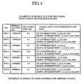
- Fig. 4 is an explanatory diagram showing, by way of example, transmission rates of the up- and the down-links for radio communication between subscriber stations and the base station; it is shown that usable transmission rates differ with the kind of multimedia that each subscriber station utilizes.
- the transmission rate identified as "intermittent" in Fig. 4 is a transmission rate below 1 kbps, and the “intermittent" transmission rate is used once for multi-frame in the mobile communication system; while the subscriber station is in the course of processing information of its own, no communications are needed between the base station and the subscriber station during this period, but this transmission rate is a low-speed one which is used when the communication line is not off.
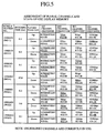
- Fig. 5 is an explanatory diagram showing a list of channels provisionally pre-assigned time slots for transmission of the next frame and channels which are actually used.
- Fig. 5 defines the kinds of transmission rates that can be changed during communication.
- This setting defines the kinds of communication channels that can be dynamically assigned.
- Fig. 5 shows that the time slot #31-0B is currently set in the Up-Link for subscriber stations Nos. 19980601 (WS21) and 19980614 (WS23) to send data therefrom to the base station at the transmission rate 1024 kbps; since this radio wave is TD-CDMA, the same time slot is shared by a plurality of signals in this case.
- spreading codes of the plural radio waves sharing the same time slot are chosen so that they cross at right angles, but in Fig. 5 information about these codes are omitted.
- Down-Link of a subscriber station No. 19980428 is shown to currently use the fourth channel (the time slot #32-1A with a transmission rate 2048 kbps); for example, when it becomes necessary to switch Down-Link to the second channel (the time slot #32-1A with a transmission rate 2 kbps) to send a small amount of information after completion of sending the large amount of information, the channel is immediately switched at that point in time.
- Fig. 6 is a state transition diagram showing channel switching.
- the state transition diagram shows the state of the downlink or uplink between one subscriber station and one base station; when plural subscriber stations are radio-connected to the base station, the number of state transition diagrams is a multiple of the number of subscriber stations connected.
- the mobile switching centers 4 and 5 control the base station, taking into consideration the current state of the subscriber stations radio-connected to the base station.
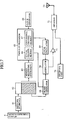
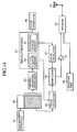
- Fig. 7 is a block diagram illustrating the inside (change request means) of the base station of the mobile communication system according to Embodiment 1 of the present invention.
- reference numeral 61 denotes a network interface which receives from a mobile switching center 4 ATM information coming from PSTN 6;
- 62 denotes a FIFO (Fast-in-Fast-out) memory which stores the ATM information received by the network interface 61;
- 63 denotes a memory measuring instrument which measures the amount of ATM information currently remaining in the FIFO memory 62 (an instantaneous amount of data which has yet to be sent to the subscriber station);
- 64 denotes a clock generator which generates a clock.
- Reference numeral 65 denotes a time slot processor which performs a selection process of selecting a time slot to be used for the transmission of the next frame in accordance with the amount of ATM information remaining in the memory measured by the memory measuring instrument 63; 66 denotes a real channel memory which stores a channel currently in use; 67 denotes a provisional channel memory provisionally pre-assigned a time slot to be used for the transmission of the next frame; 68 denotes a frame generator which, under instructions from the time slot processor 65, extracts from the FIFO memory 62 the ATM information to be sent to the subscriber station, adds the ATM information with TS change information (change information about he time slot to be used for the transmission of the next frame) and check information and generates a frame which is sent to the subscriber station; 69 denotes a local oscillator which generates a carrier under instructions from the time slot processor 65; and 70 denotes a modulator by which the frame generated by the frame generator 68 is modulated to the carrier generated by the local
- Reference numeral 71 denotes an amplifier for amplifying the carrier which is output from the modulator 70; 72 denotes a diplexer; 73 denotes an antenna; and 74 denotes a receiving part.
- Embodiment 1 Next, the operation of Embodiment 1 will be described below.
- the network interface 61 In the first place, upon receiving from the mobile switching center 4 (see Fig. 16 ) the ATM information coming from the PSTN 6, the network interface 61 stores the ATM information in the FIFO memory 62.
- the transmission rate of the ATM information that the network interface 61 is not constant owing to the characteristic of the ATM transmission system; hence, for example, if the transmission rate of the ATM information is made constant which is sent after being read out of the FIFO memory 62, the amount of ATM information remaining in the FIFO memory 62 varies.
- the memory measuring instrument 63 measures the amount of ATM information currently remaining in the FIFO memory 62 and outputs the measured amount of information remaining in the memory to the time slot processor 65.
- the time slot processor 65 When the amount of ATM information remaining differs from that in the previous frame transmission, the time slot processor 65 outputs a TS change information adding instruction to the frame generator 68 to suppress a change in the amount of information remaining.
- the time slot processor retrieves the following four inequalities for an inequality for which an inequality sign holds, and selects, as the time slot for the next frame transmission over the downlink of the subscriber station, the time slot set in the channel corresponding to the inequality for which an inequality sign holds (see Fig. 5 ). It is assumed here that the time length of one frame is 10 ms.
- the time slot processor 65 selects the time slot for the next frame transmission as described above, it supplies the frame generator 68 with an instruction for adding TS change information indicating the selected time slot and a frame generating instruction (no frame generating instruction being needed when the TS change information adding instruction is used also as the frame generating instruction).
- the time slot processor outputs only the frame generating instruction to the frame generator 68 without outputting thereto the TS change information adding instruction.
- the frame generator 68 adds, as depicted in Fig. 8 , TS change information and check information (for example, CRC code) to the ATM information read out of the FIFO memory 62 (The amount of ATM information read out of the memory is determined under instructions from the time slot processor 65 but corresponds to the transmission rate of the time slot determined at the time of the previous frame transmission. For example, when the time slot #31-1A of the transmission rate 2048 kbps was selected at the time of previous transmission, ATM information of 20.48 kbps is read out of the FIFO memory 62), thereby forming the frame that is sent to the subscriber station MS11.
- TS change information and check information for example, CRC code
- the frame generator when receiving only the frame generating instructions, adds the check information to the ATM information to form the frame.
- the local oscillator 69 generates a carrier under instructions from the time slot processor 65. That is, the oscillator generates a carrier which corresponds to the transmission rate of the time slot determined at the time of sending the previous frame.
- the modulator 70 modulates the frame to the carrier generated by the local oscillator 69, and provides the modulated output to the amplifier 71, whose output is sent by radio waves from the antenna 73.
- the subscriber station MS11 receives the radio waves.
- time slot change means of the subscriber station MS 11 changes the transmission rate for reception of the next frame, that is, the time slot for reception of the next frame in accordance with the TS change information.
- Embodiment 1 has a configuration in which upon receiving the TS change information from the base station 1, the subscriber station MS11 changes the time slot for reception of the frame from the base station 1 in accordance with the TS change information, the base station 1 can use the new time slot to send the next and subsequent frames without having to receive acceptance/rejection information which would otherwise be sent from the subscriber station in reply to the TS change information; hence, even when the amount of ATM information to be sent varies greatly, it is possible to ensure the immediacy of ATM information sent in real time.
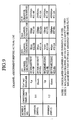
- the time slot processor 65 retrieves an inequality for which an inequality sign holds, and selects the time slot set in the channel corresponding to the inequality, but it is also possible to employ a configuration in which a time slot is provisionally pre-assigned to each channel as depicted in Fig. 9 and, when it is becomes necessary to change the transmission rate, the channel is used which has been pre-assigned the time slot of the required transmission rate.
- the time slot processor 65 determines the transmission rate for the next frame based on the amount of ATM information remaining. Concretely, if the time length of one frame is 10 ms, the time slot processor multiplies the amount of ATM information remaining by 100 to provisionally determine the transmission rate for the next frame.
- the transmission rate for the next frame is provisionally determined to be 35 Kbps.
- the time slot processor 65 refers to the provisional channel memory 67 in which a time slot has been provisionally assigned, and selects the channel corresponding to the provisionally determined transmission rate. For instance, when the transmission rate of the downlink for transmission to the subscriber station MS11 is provisionally determined to be 35 Kbps, the third channel (time slot #37-0A of 32 kbps) is selected.
- the time slot processor 65 transfers the channel information to the actual channel memory 66 to perform a process for changing the transmission rate for the next frame and, at the same time, adds the TS change information to the ATM information for transmission to the subscriber station MS11 as in Embodiment 1.
- a certain amount of time is needed to update the stored contents of the actual channel memory 66 after a request change of the transmission rate is made; hence, when the same time slot has been assigned to plural channels (in the case of Fig. 9 , the same time slot has been assigned to the third channel of the downlink of the subscriber station MS11 and the third channel of the downlink of the subscriber station MS12), if requests for change of the transmission rate in plural radio channels are made at about the same time, there is a case where the transmission rate in one of the plural radio channels cannot be changed.
- the downlink of the subscriber station MS11 is changed to the third channel (time slot #37-0A of 32 kbps)
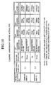
- the downlink of the subscriber station MS12 cannot be changed to the third channel (time slot #37-0A of 32 kbps); hence, as depicted in Fig. 10 , that one of currently unused time slots which has a time slot equal to that of the time slot #37-0A (for example, time slot #37-3A) is assigned to the third channel concerned.
- the downlink of the subscriber station MS12 is switched to the third channel (time slot #37-3A of 32 kbps).
- Embodiment 1 described above upon receiving the TS change information from the time slot processor 65 sends the TS change information, the subscriber station immediately changes the time slot, but it is also possible to employ a configuration in which the time slot processor sends to the subscriber station reservation information indicating the timing for changing the time slot and the subscriber station determines the time slot change timing in accordance with the reservation information.
- the time slot processor 65 adds the ATM information with the reservation information indicating the timing for changing the time slot (for example, when "-5" is added as the reservation information, the time slot is changed after five frames) as shown in Fig. 11 .
- the subscriber station upon receiving the ATM information added with the TS change information and the reservation information, changes the time slot in accordance with the TS change information as in Embodiment 1 described above, but it does not necessarily change the time slot immediately after receiving the TS change information but instead determines the timing for changing the time slot in accordance with the reservation information.
- the subscriber station uses the new time slot after the lapse of five frame periods.
- the subscriber station count reservation information up by one (-5" ⁇ "-4" ⁇ “-3” ⁇ “-2” ⁇ “-1” ⁇ “0") upon each sending of the ATM information from the time slot processor 65 and changes the time slot when the reservation information reaches "0"; alternatively, the time slot processor 65 sends the reservation information once and the subscriber station counts the number of times it receives frames after the reception of the reservation information, thereby obtaining the timing for changing the time slot.
- Embodiment 3 is adapted to send the TS change information to the subscriber station together with the reservation information indicating the timing for changing the time slot, the time slot changing process can be prepared in anticipation of a variation in the amount of data to be sent; accordingly, the time slot can be changed in good time, making it possible to judge the state of congestion in the frequency band used.
- slots with no ATM information can also be reserved in the previous frame (it can also be set that, for example, reservation information "2" means that no information will be contained in the time slots for the subsequent two frames), equivalent noise can be reduced when the time division CDMA system is adopted.
- the subscriber station determines the time slot change timing based on the reservation information sent thereto, but since in this instance the time slot is actually changed several frames after the sending of the TS change information, another subscriber station may sometimes use the time slot concerned, making it impossible to use the desired time slot.
- Embodiment 4 is adapted so that when the desired time slot becomes unusable before the time slot changing means of the subscriber station changes the time slot, the time slot processor 65 sends TS correcting information designating another time slot to the subscriber station as shown in Fig. 12 .
- the time slot changing means of the subscriber station changes the time slot based on the TS correcting information; accordingly, even if the desired time slot becomes unusable, it is possible to secure the required transmission rate.
- the subscriber station determines the time slot change timing based on the reservation information sent thereto, it is also possible to reserve a change of the time slot provisionally assigned to each channel.
- the time slot processor 65 sends reservation information to the subscriber station, the time slot is changed after several frames and the stored contents of the provisional channel memory 67 are reflected on the actual channel memory 66; however, to cope with variations in the amount of data to be sent after several frames, it is also possible to accept a reservation that updates the stored contents of the provisional channel memory 67.
- a reservation is made which provisionally assigns #32-2A to the downlink of the second channel of the subscriber station MS11 after several frames.
- Embodiments 1 through 5 described above upon receiving the TS change information sent from the time slot processor, the subscriber station changes the time slot based on the TS change information, but unconditional change of the time slot entails the risk of cutting the radio connection.
- Embodiment 6 is designed so that the change of the time slot is allowed as long as the state of current radio communication meets predetermined conditions.
- step ST1 when a request for a change of the channel capacity is made (step ST1), the time slot processor 65 judges whether the new channel capacity is larger than the channel capacity currently used for communication (step ST2).
- the time slot processor 65 judges whether the transmitter of the base station can increase the current sending power by C (dB) (step ST4).
- the time slot processor 65 permits the change of the channel capacity (step ST5) and sends the TS change information to the subscriber station in the same manner as described above with reference to Embodiments 1 to 5.
- step ST6 when the transmitter of the base station cannot increase the current sending power by C (dB), an increase in the channel capacity will be likely to cause cutting the radio connection, and hence the time slot processor does not permit the change of the channel capacity (step ST6) and stops sending the TS change information.
- the sending power of the transmitter of the base station can be increased to some extent, it is possible to set the channel capacity corresponding to the amount of increase and send the TS change information accordingly.
- the time slot processor 65 compares the sensitivity of the receiver of the subscriber station and its minimum sensitivity and judges whether the sensitivity of the receiver of the subscriber station is higher than the minimum sensitivity in excess of A dB (sep ST7).
- the time slot processor permits a change of the channel capacity and sends the TS change information to the subscriber station.
- the time slot processor judges whether the current sending power of the transmitter of the base station can be increase by A (dB) (step ST8).
- the time slot processor judges whether the current sending power of the transmitter of the base station can be increased by A (dB).
- the time slot processor permits a change of the channel capacity and sends the TS change information to the subscriber station.
- the time slot processor does not permit a change of the channel capacity (step ST6) and stops sending the TS change information.
- Embodiment 6 when the channel capacity increases, it is determined whether to permit or inhibit the change of the transmission by referring to the sendable power of the transmitter in the base station, and when the channel capacity decreases, it is determined whether to permit or inhibit the change of the transmission rate by referring to the sensitivity of the receiver in the subscriber station and the sendable power of the transmitter in the base station; hence, this embodiment obviates the defect of the radio connection being cut by a change of the time slot.
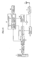
- Fig. 14 is a block diagram illustrating the inside (change request means) of the subscriber station in the mobile communication system according to Embodiment 7 of the present invention.
- reference numeral 81 denotes a man-machine interface such as a keyboard, image display part, voice input/output part or the like
- 82 denotes a FIFO memory for storing data input from the man-machine interface 81
- 83 denotes a memory measuring instrument for measuring the amount of information currently remaining in the FIFO memory 82 (the instantaneous amount of data which has yet to be sent to the subscriber station)
- 84 denotes a clock generator for generating a clock.
- Reference numeral 85 denotes a time slot processor which performs a selection process of selecting a time slot to be used for the transmission of the next frame in accordance with the amount of data remaining in the memory measured by the memory measuring instrument 83; 86 denotes an actual channel memory which stores a channel currently in use; 87 denotes a provisional channel memory provisionally pre-assigned a time slot to be used for the transmission of the next frame; 88 denotes a frame generator which, under instructions from the time slot processor 85, extracts from the FIFO memory 82 the data to be sent to the subscriber station, and adds the data with TS change information and check information to form a frame which is sent to the subscriber station; 89 denotes a local oscillator which generates a carrier under instructions from the time slot processor 85; and 90 denotes a modulator by which the frame generated by the frame generator 88 is modulated to the carrier generated by the local oscillator 89.
- Reference numeral 91 denotes an amplifier for amplifying the carrier which is output from the modulator 90; 92 denotes a diplexer; 93 denotes an antenna; and 94 denotes a receiving part.
- the subscriber station may also be designed to change the time slot independently by incorporating in the subscriber station the same change request means as that of the base station depicted in Fig. 7 .
- the time slot processor 85 of the subscriber station determines the time slot for the transmission of the next frame (or for the transmission after several frames) in accordance with the amount of data remaining in the memory measured by the memory measuring instrument 83, and sends to the base station a frame in which TS change information and reservation information are added to transmission data.
- Fig. 15 is a block diagram illustrating time slot changing means of the base station which receives the TS change information from the subscriber station and changes the time slot (the time slot changing means of the subscriber station being also substantially identical in construction therewith).
- reference numeral 101 denotes a receiving part for receiving the frame added with the TS change information
- 102 denotes a receiving local oscillator
- 103 denotes a demodulator for demodulating the frame received by the receiving part 101
- 104 denotes a frame decoding/data detector which decodes the frame demodulated by the demodulator 103 and, when detecting the TS change information, outputs the TS change information to the time slot processor 65.
- the time slot processor 65 Upon receiving the TS change information from the frame decoding/data detector 104, the time slot processor 65 changes the time slot for reception of the next frame in accordance with the TS change information.
- the mobile communication system has a communication channel in which uplink and downlink channel capacities differ from each other, and is suitable for use with such transmission systems as a time division multiple access (TDMA) system, a code division multiple access/time division duplex (CDMA/TDD) system, and a time division CDMA (Time Divided CDMA) system.
- TDMA time division multiple access
- CDMA/TDD code division multiple access/time division duplex
- CDMA Time Division CDMA
Landscapes
- Engineering & Computer Science (AREA)
- Computer Networks & Wireless Communication (AREA)
- Signal Processing (AREA)
- Mobile Radio Communication Systems (AREA)
Claims (20)
- Verfahren zum Ändern der Datenübertragungsraten innerhalb eines Mobilkommunikationsnetzwerks, bei welchem ein Änderungs-Anforderungselement (61-72) von einer Basisstation (1-3) eine Zeitschlitz-Änderungsinformation an eine damit verbundene Teilnehmerstation über Funk sendet, um einen Zeitschlitz zu ändern, welcher eine unterschiedliche zugehörige Übertragungsrate hat, wenn es notwendig wird, die Übertragungsrate für Daten, welche an die Teilnehmerstation zu senden sind, zu ändern; und wobei ein Zeitschlitz-Änderungselement (85) von der Teilnehmerstation bei einem Empfang von der Zeitschlitz-Änderungsinformation von dem Änderungs-Anforderungselement (61-72) von der Basisstation (1-3) den Zeitschlitz, innerhalb dessen Daten von der Basisstation (1-3) zu empfangen sind, gemäß der Zeitschlitz-Änderungsinformation ändert,
dadurch gekennzeichnet, dass
wenn das Änderungs-Anforderungselement (61-72) in der Basisstation (1-3) eine Änderung von dem Zeitschlitz anfordert, um eine erhöhte Übertragungsrate zu geben, das Änderungs-Anforderungselement (61-72) bestimmt, ob eine Änderung in der Übertragungsleistung gemäß der neuen Übertragungsrate in dem Übertrager in der Basisstation möglich ist, wenn die neue Übertragungsleistung möglich ist, das Änderungs-Anforderungselement (61-72) eine Änderung von der Übertragungsrate zulässt, und wenn die neue Übertragungsleistung nicht möglich ist, das Änderungs-Anforderungselement (61-72) die Änderung der Übertragungsrate nicht zulässt. - Verfahren zum Ändern von Datenkommunikationsraten innerhalb eines Mobilkommunikationsnetzwerks nach Anspruch 1, bei welchem, nach dem Senden der Zeitschlitz-Änderungsinformation an die Teilnehmerstation, das Änderungs-Anforderungselement von der Basisstation damit beginnt, den neuen Zeitschlitz zum Senden von Daten, welche in den nächsten Rahmen enthalten sind, zu verwenden.
- Verfahren zum Ändern von Datenübertragungsraten innerhalb eines Mobilkommunikationsnetzwerks nach Anspruch 1, bei welchem das Änderungs-Anforderungselement von der Basisstation die Übertragungsrate gemäß einer augenblicklichen Datenmenge bestimmt, welche an die Teilnehmerstation zu senden ist.
- Verfahren zum Ändern von Datenübertragungsraten innerhalb eines Mobilkommunikationsnetzwerks nach Anspruch 3, bei welchem das Änderungs-Anforderungselement von der Basisstation die augenblickliche Datenmenge anhand von jener Datenmenge erfasst, welche von einem Vermittlungszentrum empfangen wird, welches noch an die Teilnehmerstation zu-senden hat.
- Verfahren zum Ändern von Datenübertragungsraten innerhalb eines Mobilkommunikationsnetzwerks nach Anspruch 1, bei welchem, zum Zeitpunkt eines Sendens der Zeitschlitz-Änderungsinformation an die Teilnehmerstation, das Änderungs-Anforderungselement von der Basisstation die Zeitschlitz-Änderungsinformation'von einem vorläufigen Kanalspeicher erlangt, wobei dieser vorläufige Kanalspeicher mit einem zuvor zugewiesenen Zeitschlitz bereitgestellt ist, welcher für die Übertragung des nächsten Rahmens zu verwenden ist.
- Verfahren zum Ändern von Datenübertragungsraten innerhalb eines Mobilkommunikationsnetzwerks nach Anspruch 1, bei welchem, wenn ein gewünschter Zeitschlitz in jenem Zeitintervall unbrauchbar wird, zwischen dem das Zeitschlitz-Änderungselement von der Teilnehmerstation die Zeitschlitz-Änderung durchführt und die Zeitschlitz-Änderungsinformation und die Reservierungsinformation an die Teilnehmerstation sendet, das Änderungs-Anforderungselement von der Basisstation jene Zeitschlitz-Änderungsinformation, welche einen weiteren Zeitschlitz anzeigt, an die Teilnehmerstation sendet.
- Verfahren zum Ändern von Datenkommunikationsraten innerhalb eines Mobilkommunikationsnetzwerks nach Anspruch 1, bei welchem, im Falle der Erhöhung der Datenübertragungsrate, das Änderungs-Anforderungselement von der Basisstation bestimmt, ob die Übertragungsrate zu ändern ist, indem auf die übertragbare Leistung eines Übertragers in der Basisstation bezuggenommen wird.
- Verfahren zum Ändern von Datenübertragungsraten innerhalb eines Mobilkommunikationsnetzwerks nach Anspruch 1, bei welchem, zum Zeitpunkt der Übertragung von der Zeitschlitz-Änderungsinformation an die Teilnehmerstation, das Änderungs-Anforderungselement von der Basisstation ebenfalls eine Reservierungsinformation, welche den Zeitpunkt der Zeitschlitzänderung anzeigt, an die Teilnehmerstation sendet; und
das Zeitschlitz-Änderungselement von der Teilnehmerstation jenen Zeitpunkt der Zeitschlitzänderung gemäß der Reservierungsinformation bestimmt, welche von der Basisstation übertragen wird. - Verfahren zum Ändern von Datenkommunikationsraten innerhalb eines Mobilkommunikationsnetzwerks nach Anspruch 7, bei welchem, im Falle der Verringerung der Datenübertragungsrate, das Änderungs-Anforderungselement von der Basisstation basierend auf der Empfindlichkeit eines Empfängers in der Teilnehmerstation und der übertragbaren Leistung eines Übertragers in der Basisstation bestimmt, ob die Übertragungsrate zu ändern ist.
- Verfahren zum Ändern von Datenübertragungsraten innerhalb eines Mobilkommunikationsnetzwerks, bei welchem das Änderungs-Anforderungselement (81-94) von einer Teilnehmerstation eine Zeitschlitz-Änderungsinformation an eine Basisstation (1-3), welche damit verbunden ist, über Funk überträgt, um einen Zeitschlitz zu ändern, welcher eine unterschiedliche zugehörige Übertragungsrate hat, wenn es notwendig wird, die Übertragungsrate für Daten zu ändern, welche an die Basisstation (1-3) zu senden sind; und
wobei ein Zeitschlitz-Änderungselement (65) von der Basisstation (1-3), beim Empfang von der Zeitschlitz-Änderungsinformation von dem Änderungs-Anforderungselement (81-94), von der Teilnehmerstation jenen Zeitschlitz, in welchem Daten von der Teilnehmerstation zu empfangen sind, gemäß der Zeitschlitz-Änderungsinformation ändert,
dadurch gekennzeichnet, dass
wenn das Änderungs-Anforderungselement (81-94) in der Teilnehmerstation eine Änderung von dem Zeitschlitz anfordert, um eine erhöhte Übertragungsrate zu geben, das Änderungs-Anforderungselement (61-72) von der Basisstation (1-3) bestimmt, ob eine Änderung in der Übertragungsleistung gemäß der neuen Übertragungsrate in dem Übertrager in der Basisstation (1-3) möglich ist, wenn die neue Übertragungsleistung möglich ist, das Änderungs-Anforderungselement (61-72) von der Basisstation (1-3) eine Änderung von der Übertragungsrate zulässt, und wenn die neue Übertragungsleistung nicht möglich ist, das Änderungs-Anforderungselement (61-72) von der Basisstation (1-3) die Änderung der Übertragungsrate nicht zulässt. - Verfahren zum Ändern von Datenübertragungsraten innerhalb eines Mobilkommunikationsnetzwerks nach Anspruch 10, bei welchem, wenn die Zeitschlitz-Änderungsinformation an die Basisstation gesendet ist, das Änderungs-Anforderungselement von der Teilnehmerstation damit beginnt, den neuen Zeitschlitz zum Senden von Daten zu verwenden, welche in dem nächsten Rahmen enthalten sind.
- Verfahren zum Ändern von Datenübertragungsraten innerhalb des Mobilkommunikationsnetzwerks nach Anspruch 10, bei welchem das Änderungs-Anforderungselement von der Teilnehmerstation die Übertragungsrate gemäß einer augenblicklichen Datenmenge, welche an die Basisstation zu senden ist, bestimmt.
- Verfahren zum Ändern von Datenübertragungsraten innerhalb des Mobilkommunikationsnetzwerks nach Anspruch 12, bei welchem das Änderungs-Anforderungselement von der Teilnehmerstation die augenblickliche Datenmenge anhand von jener Datenmenge erfasst, welche von einer Bedienoberfläche empfangen wird, welche noch an die Teilnehmerstation zu übertragen ist.
- Verfahren zum Ändern von Datenübertragungsraten innerhalb des Mobilkommunikationsnetzwerks nach Anspruch 10, bei welchem, zum Zeitpunkt der Übertragung von der Zeitschlitz-Änderungsinformation an die Basisstation, das Änderungs-Anforderungselement von der Teilnehmerstation die Zeitschlitz-Änderungsinformation von einem vorläufigen Kanalspeicher
erlangt, wobei dieser vorläufige Kanalspeicher mit einem zuvor zugewiesenen Zeitschlitz bereitgestellt ist, welcher zur Übertragung des nächsten Rahmens zu verwenden ist. - Verfahren zum Ändern von Datenübertragungsraten innerhalb eines Mobilfunknetzwerks nach Anspruch 10, bei welchem, wenn ein gewünschter Zeitschlitz in jenem Intervall unbrauchbar wird, zwischen dem das Zeitschlitz-Änderungselement von der Basisstation die Zeitschlitz-Änderung durchführt und die Zeitschlitz-Änderungsinformation und die Reservierungsinformation an die Basisstation übertragen wird, das Änderungs-Anforderungselement von der Teilnehmerstation die Zeitschlitz-Änderungsinformation, welche einen weiteren Zeitschlitz anzeigt, an die Basisstation überträgt.
- Verfahren zum Ändern von Datenübertragungsraten innerhalb eines Mobilkommunikationswerks nach Anspruch 10, bei welchem, im Falle der Änderung der Datenübertragungsraten, das Änderungs-Anforderungselement von der Teilnehmerstation unter Bezugnahme auf die übertragbare Leistung eines Übertragers in der Teilnehmerstation bestimmt, ob die Übertragungsrate zu ändern ist.
- Verfahren zum Ändern von Datenübertragungsraten innerhalb eines Mobilkommunikationsnetzwerks nach Anspruch 16, bei welchem, im Falle der Erhöhung der Datenübertragungsrate, das Änderungs-Anforderungselement von der Teilnehmerstation unter Bezugnahme auf die übertragbare Leistung eines Übertragers in der Teilnehmerstation bestimmt, ob die Übertragungsrate zu ändern ist.
- Verfahren zum Ändern von Datenübertragungsraten innerhalb eines Mobilkommunikationsnetzwerks nach Anspruch 16, bei welchem, im Falle der Verringerung der Datenübertragungsrate, das Änderungs-Anforderungselement von der Teilnehmerstation basierend auf der Empfindlichkeit eines Empfängers in der Basisstation und der übertragbaren Leistung eines Übertragers in der Teilnehmerstation bestimmt, ob die Übertragungsrate zu ändern ist.
- Mobilkommunikationsnetzwerk, welches zumindest eine Basisstation und zumindest eine Teilnehmerstation enthält, wobei die Änderungs-Anforderungselemente (61-72) von einer Basisstation (1-3) dazu ausgelegt sind, eine Zeitschlitz-Änderungsinformation an eine damit verbundene Teilnehmerstation über Funk zu übertragen, um einen Zeitschlitz zu ändern, welcher eine unterschiedliche zugehörige Übertragungsrate hat, wenn es notwendig wird, die Übertragungsrate für Daten zu ändern, welche an die Teilnehmerstation zu übertragen sind, und wobei Zeitschlitz-Änderungselemente (85) von der Teilnehmerstation, nach einem Empfang von der Zeitschlitz-Änderungsinformation von den Änderungs-Anforderungselementen (61-72) von der Basisstation (1-3), dazu ausgelegt sind, jenen Zeitschlitz, in welchem Daten von der Basisstation (1-3) zu empfangen sind, gemäß der Zeitschlitz-Änderungsinformation zu ändern,
dadurch gekennzeichnet, dass
in Ansprechen auf die Änderungs-Anforderungselemente (61-72) in der Basisstation (1-3), welche eine Änderung des Zeitschlitzes anfordern, um eine erhöhte Übertragungsrate zu erhalten, das Änderungs-Anforderungselement (61-72) dazu ausgelegt ist, zu bestimmen, ob eine Änderung in der Übertragungsleistung entsprechend der neuen Übertragungsrate in dem Übertrager in der Basisstation möglich ist, wobei, wenn die neue Übertragungsleistung möglich ist, das Änderungs-Anforderungselement (61-72) dazu ausgelegt ist, eine Änderung der Übertragungsrate zuzulassen, wobei, wenn die neue Übertragungsleistung nicht möglich ist, das Änderungs-Anforderungselement (61-72) dazu ausgelegt ist, die Änderung der Übertragungsrate nicht zuzulassen. - Mobilkommunikationsnetzwerk, welches zumindest eine Basisstation und zumindest eine Teilnehmerstation enthält, wobei die Änderungs-Anforderungselemente (81-94) von einer Teilnehmerstation dazu ausgelegt sind, eine Zeitschlitz-Änderungsinformation an eine Basisstation (1-3), welche damit verbunden ist, über Funk zu übertragen, um einen Zeitschlitz zu ändern, welcher eine unterschiedliche zugehörige Übertragungsrate hat, wenn es notwendig wird, die Übertragungsrate für Daten zu ändern, welche an die Basisstation (1-3) zu übertragen sind; und
wobei Zeitschlitz-Änderungselemente (65) von der Basisstation (1-3) bei einem Empfang von der Zeitschlitz-Änderungsinformation von dem Änderungs-Anforderungselement (81-94) von der Teilnehmerstation dazu ausgelegt sind, den Zeitschlitz, innerhalb dessen Daten von der Teilnehmerstation zu empfangen sind, gemäß der Zeitschlitz-Änderungsinformation zu ändern,
dadurch gekennzeichnet, dass
in Ansprechen auf die Änderungs-Anforderungselemente (81-94) in der Teilnehmerstation (1-3), welche eine Änderung des Zeitschlitzes anfordern, um eine erhöhte Übertragungsrate zu erhalten, die Änderungs-Anforderungselemente (61-72) in der Basisstation (1-3) dazu ausgelegt sind, zu bestimmen, ob eine Änderung in der Übertragungsleistung entsprechend der neuen Übertragungsrate im Übertrager in der Basisstation möglich ist, wobei, wenn die neue Übertragungsleistung möglich ist, die Änderungs-Anforderungselemente (61-72) in der Basisstation (1-3) dazu ausgelegt sind, eine Änderung von der Übertragungsrate zuzulassen, wobei, wenn die neue Übertragungsleistung nicht möglich ist, die Änderungs-Anforderungselemente (61-72) von der Basisstation (1-3) dazu ausgelegt sind, die Änderung der Übertragungsrate nicht zuzulassen.
Applications Claiming Priority (1)
| Application Number | Priority Date | Filing Date | Title |
|---|---|---|---|
| PCT/JP1999/001295 WO2000056108A1 (en) | 1999-03-16 | 1999-03-16 | Mobile communication system |
Publications (3)
| Publication Number | Publication Date |
|---|---|
| EP1081981A1 EP1081981A1 (de) | 2001-03-07 |
| EP1081981A4 EP1081981A4 (de) | 2004-04-21 |
| EP1081981B1 true EP1081981B1 (de) | 2010-12-29 |
Family
ID=14235201
Family Applications (1)
| Application Number | Title | Priority Date | Filing Date |
|---|---|---|---|
| EP99907950A Expired - Lifetime EP1081981B1 (de) | 1999-03-16 | 1999-03-16 | Dynamische Veränderung der Datenrate |
Country Status (4)
| Country | Link |
|---|---|
| US (1) | US6958985B1 (de) |
| EP (1) | EP1081981B1 (de) |
| DE (1) | DE69943085D1 (de) |
| WO (1) | WO2000056108A1 (de) |
Families Citing this family (7)
| Publication number | Priority date | Publication date | Assignee | Title |
|---|---|---|---|---|
| US6804220B2 (en) * | 2001-05-07 | 2004-10-12 | Qualcomm Incorporated | Method and apparatus for generating control information for packet data |
| DE10122419B4 (de) * | 2001-05-09 | 2007-11-08 | Siemens Ag | Verfahren zur dynammischen Kanalzuordnung |
| JP3442380B2 (ja) | 2002-10-16 | 2003-09-02 | 富士通テン株式会社 | 移動体通信用送受信装置 |
| JP3442381B2 (ja) | 2002-10-16 | 2003-09-02 | 富士通テン株式会社 | 移動体通信用送受信装置 |
| US20070075838A1 (en) * | 2005-10-04 | 2007-04-05 | Symbol Technologies, Inc. | Method and apparatus for avoiding radio frequency identification (RFID) tag response collisions |
| JP4918852B2 (ja) * | 2006-12-12 | 2012-04-18 | 富士通株式会社 | 電力割当方法及びそれを用いた無線基地局装置 |
| JP5413063B2 (ja) * | 2009-09-01 | 2014-02-12 | 住友電気工業株式会社 | 通信制御装置、路側通信機、移動通信機及び通信システム |
Family Cites Families (16)
| Publication number | Priority date | Publication date | Assignee | Title |
|---|---|---|---|---|
| SE500157C2 (sv) * | 1989-09-13 | 1994-04-25 | Ericsson Telefon Ab L M | Förfarande för att välja basstation, radiokanal och tidslucka vid en mobilstation |
| US5896561A (en) * | 1992-04-06 | 1999-04-20 | Intermec Ip Corp. | Communication network having a dormant polling protocol |
| JP3287023B2 (ja) * | 1992-07-29 | 2002-05-27 | 日本電気株式会社 | 衛星チャネルアクセスシステム |
| US5535207A (en) * | 1994-05-20 | 1996-07-09 | Motorola, Inc. | Method of dynamically allocating time slots on a packet data communications channel |
| FI98427C (fi) * | 1994-06-08 | 1997-06-10 | Nokia Mobile Phones Ltd | Järjestelmäpakettidatan siirtämiseksi eri bittinopeuksilla TDMA-solukkojärjestelmässä |
| JP3215018B2 (ja) | 1994-09-09 | 2001-10-02 | 三菱電機株式会社 | 移動通信システム |
| US5598417A (en) * | 1995-04-28 | 1997-01-28 | Motorola, Inc. | Dynamic control of a data channel in a TDM wireless communication system |
| US6272325B1 (en) * | 1995-07-13 | 2001-08-07 | Globalstar L.P. | Method and apparatus for considering user terminal transmitted power during operation in a plurality of different communication systems |
| US5719859A (en) * | 1995-09-19 | 1998-02-17 | Matsushita Electric Industrial Co., Ltd. | Time division multiple access radio communication system |
| US5701294A (en) * | 1995-10-02 | 1997-12-23 | Telefonaktiebolaget Lm Ericsson | System and method for flexible coding, modulation, and time slot allocation in a radio telecommunications network |
| US5818830A (en) | 1995-12-29 | 1998-10-06 | Lsi Logic Corporation | Method and apparatus for increasing the effective bandwidth of a digital wireless network |
| JPH1065604A (ja) * | 1996-08-23 | 1998-03-06 | Sony Corp | 通信方法、基地局及び端末装置 |
| DE69739958D1 (de) * | 1997-06-16 | 2010-09-23 | Mitsubishi Electric Corp | Mobilkommunikationssystem |
| US6574211B2 (en) * | 1997-11-03 | 2003-06-03 | Qualcomm Incorporated | Method and apparatus for high rate packet data transmission |
| JP3226022B2 (ja) * | 1997-11-14 | 2001-11-05 | 日本電気株式会社 | 通信制御方法およびその装置 |
| KR20000019059A (ko) * | 1998-09-08 | 2000-04-06 | 윤종용 | 무선 가입자망 시스템에서 데이터 전송방식에 따른 자원할당및 해제방법 |
-
1999
- 1999-03-16 EP EP99907950A patent/EP1081981B1/de not_active Expired - Lifetime
- 1999-03-16 DE DE69943085T patent/DE69943085D1/de not_active Expired - Lifetime
- 1999-03-16 WO PCT/JP1999/001295 patent/WO2000056108A1/ja not_active Ceased
-
2000
- 2000-10-17 US US09/688,814 patent/US6958985B1/en not_active Expired - Lifetime
Also Published As
| Publication number | Publication date |
|---|---|
| EP1081981A4 (de) | 2004-04-21 |
| DE69943085D1 (de) | 2011-02-10 |
| EP1081981A1 (de) | 2001-03-07 |
| US6958985B1 (en) | 2005-10-25 |
| WO2000056108A1 (en) | 2000-09-21 |
Similar Documents
| Publication | Publication Date | Title |
|---|---|---|
| JP3349477B2 (ja) | 移動体通信機、移動体通信システムおよび通話チャネル割当要求方法 | |
| KR100812654B1 (ko) | 적응 변조 및 코딩 기법을 위한 공통 제어 채널 업링크 전력 제어 | |
| EP1596621B1 (de) | Vorrichtung zur Funkressourcenzuweisung | |
| EP1217852B1 (de) | Verfahren zur Funkbetriebsmittelzuweisung und Basisstation unter Verwendung desselben | |
| EP1282241B1 (de) | Mobilkommunikationssystem und Verfahren zur Sendeleistungsregelung | |
| EP1371165B1 (de) | Verfahren und vorrichtung zur steuerung der datenrate in einem kommunikationssystem | |
| EP0809365A1 (de) | Schema zur Steuerung der Sendeleitungen während des sanften Weiterreichens in einem CDMA-Mobilfunkkommunicationssystem | |
| US7486956B2 (en) | Channel estimation and channel quality indicator (CQI) measurements for a high-speed downlink GPRS | |
| AU2002259200A1 (en) | Common control channel uplink power control for adaptive modulation and coding techniques | |
| EP1034642B1 (de) | Telekommunikationssystem mit kanalteilung | |
| EP1081981B1 (de) | Dynamische Veränderung der Datenrate | |
| EP2262299A2 (de) | Verfahren zur Funkzellenausdehnung in einem zellulären TDMA-Telefonsystem | |
| EP1204286B1 (de) | Kommunikationsendgerätevorrichtung, basisstationsvorrichtung und funkkommunikationsverfahren | |
| US20040132460A1 (en) | Method for preventing overload in base station and base station system thereof | |
| WO2002032157A2 (en) | Mobile station driven cell switching and handoff with load balancing for wireless systems | |
| EP1903721B1 (de) | Arbitrierungsverfahren für Übertragungen mit hoher Leistung in einem CDMA-System | |
| JP4602456B2 (ja) | 移動通信システム、基地局及び加入者局 | |
| GB2332595A (en) | Slot Allocation in a TDD Wireless Communication System | |
| JPWO2000056108A1 (ja) | 移動通信システム | |
| RU2263414C2 (ru) | Способ расширения сотовой ячейки в сотовой телефонной системе мдвр | |
| HK1118994B (en) | Arbitration method for high power transmissions in a code division multiple access system |
Legal Events
| Date | Code | Title | Description |
|---|---|---|---|
| PUAI | Public reference made under article 153(3) epc to a published international application that has entered the european phase |
Free format text: ORIGINAL CODE: 0009012 |
|
| 17P | Request for examination filed |
Effective date: 20001114 |
|
| AK | Designated contracting states |
Kind code of ref document: A1 Designated state(s): DE FR GB SE |
|
| A4 | Supplementary search report drawn up and despatched |
Effective date: 20040304 |
|
| RIC1 | Information provided on ipc code assigned before grant |
Ipc: 7H 04B 7/26 B Ipc: 7H 04Q 7/22 A |
|
| 17Q | First examination report despatched |
Effective date: 20040510 |
|
| RAP1 | Party data changed (applicant data changed or rights of an application transferred) |
Owner name: MITSUBISHI DENKI KABUSHIKI KAISHA |
|
| RIC1 | Information provided on ipc code assigned before grant |
Ipc: H04W 52/04 20090101AFI20091204BHEP |
|
| RTI1 | Title (correction) |
Free format text: CHANGING TRANSMISSION RATE DYNAMICALLY |
|
| RIC1 | Information provided on ipc code assigned before grant |
Ipc: H04W 52/04 20090101AFI20100503BHEP |
|
| GRAP | Despatch of communication of intention to grant a patent |
Free format text: ORIGINAL CODE: EPIDOSNIGR1 |
|
| GRAS | Grant fee paid |
Free format text: ORIGINAL CODE: EPIDOSNIGR3 |
|
| GRAA | (expected) grant |
Free format text: ORIGINAL CODE: 0009210 |
|
| AK | Designated contracting states |
Kind code of ref document: B1 Designated state(s): DE FR GB SE |
|
| REG | Reference to a national code |
Ref country code: GB Ref legal event code: FG4D |
|
| REF | Corresponds to: |
Ref document number: 69943085 Country of ref document: DE Date of ref document: 20110210 Kind code of ref document: P |
|
| REG | Reference to a national code |
Ref country code: DE Ref legal event code: R096 Ref document number: 69943085 Country of ref document: DE Effective date: 20110210 |
|
| PG25 | Lapsed in a contracting state [announced via postgrant information from national office to epo] |
Ref country code: SE Free format text: LAPSE BECAUSE OF FAILURE TO SUBMIT A TRANSLATION OF THE DESCRIPTION OR TO PAY THE FEE WITHIN THE PRESCRIBED TIME-LIMIT Effective date: 20101229 |
|
| PLBE | No opposition filed within time limit |
Free format text: ORIGINAL CODE: 0009261 |
|
| STAA | Information on the status of an ep patent application or granted ep patent |
Free format text: STATUS: NO OPPOSITION FILED WITHIN TIME LIMIT |
|
| 26N | No opposition filed |
Effective date: 20110930 |
|
| REG | Reference to a national code |
Ref country code: DE Ref legal event code: R097 Ref document number: 69943085 Country of ref document: DE Effective date: 20110930 |
|
| REG | Reference to a national code |
Ref country code: DE Ref legal event code: R082 Ref document number: 69943085 Country of ref document: DE Representative=s name: MEISSNER BOLTE PATENTANWAELTE RECHTSANWAELTE P, DE Ref country code: DE Ref legal event code: R082 Ref document number: 69943085 Country of ref document: DE Representative=s name: MEISSNER, BOLTE & PARTNER GBR, DE Ref country code: DE Ref legal event code: R081 Ref document number: 69943085 Country of ref document: DE Owner name: TCL COMMUNICATION TECHNOLOGY HOLDINGS LTD., KO, HK Free format text: FORMER OWNER: MITSUBISHI DENKI K.K., TOKYO, JP |
|
| REG | Reference to a national code |
Ref country code: GB Ref legal event code: 732E Free format text: REGISTERED BETWEEN 20150604 AND 20150610 |
|
| REG | Reference to a national code |
Ref country code: FR Ref legal event code: TP Owner name: TCL COMMUNICATION TECHNOLOGY HOLDINGS LIMITED, CN Effective date: 20150918 |
|
| REG | Reference to a national code |
Ref country code: FR Ref legal event code: PLFP Year of fee payment: 18 |
|
| REG | Reference to a national code |
Ref country code: FR Ref legal event code: PLFP Year of fee payment: 19 |
|
| REG | Reference to a national code |
Ref country code: FR Ref legal event code: PLFP Year of fee payment: 20 |
|
| PGFP | Annual fee paid to national office [announced via postgrant information from national office to epo] |
Ref country code: GB Payment date: 20180314 Year of fee payment: 20 Ref country code: DE Payment date: 20180306 Year of fee payment: 20 |
|
| PGFP | Annual fee paid to national office [announced via postgrant information from national office to epo] |
Ref country code: FR Payment date: 20180223 Year of fee payment: 20 |
|
| REG | Reference to a national code |
Ref country code: DE Ref legal event code: R071 Ref document number: 69943085 Country of ref document: DE |
|
| REG | Reference to a national code |
Ref country code: GB Ref legal event code: PE20 Expiry date: 20190315 |
|
| PG25 | Lapsed in a contracting state [announced via postgrant information from national office to epo] |
Ref country code: GB Free format text: LAPSE BECAUSE OF EXPIRATION OF PROTECTION Effective date: 20190315 |