EP1080992A2 - Ablagefach (Kartenfach) - Google Patents
Ablagefach (Kartenfach) Download PDFInfo
- Publication number
- EP1080992A2 EP1080992A2 EP00116583A EP00116583A EP1080992A2 EP 1080992 A2 EP1080992 A2 EP 1080992A2 EP 00116583 A EP00116583 A EP 00116583A EP 00116583 A EP00116583 A EP 00116583A EP 1080992 A2 EP1080992 A2 EP 1080992A2
- Authority
- EP
- European Patent Office
- Prior art keywords
- pressure element
- storage compartment
- pressure
- guide
- guideways
- Prior art date
- Legal status (The legal status is an assumption and is not a legal conclusion. Google has not performed a legal analysis and makes no representation as to the accuracy of the status listed.)
- Granted
Links
Images


Classifications
-
- B—PERFORMING OPERATIONS; TRANSPORTING
- B60—VEHICLES IN GENERAL
- B60R—VEHICLES, VEHICLE FITTINGS, OR VEHICLE PARTS, NOT OTHERWISE PROVIDED FOR
- B60R7/00—Stowing or holding appliances inside vehicle primarily intended for personal property smaller than suit-cases, e.g. travelling articles, or maps
- B60R7/08—Disposition of racks, clips, holders, containers or the like for supporting specific articles
- B60R7/081—Disposition of racks, clips, holders, containers or the like for supporting specific articles for supporting maps
Definitions
- the invention relates to a storage compartment (card compartment) for storing flat objects like maps in a car.
- the invention has for its object to propose such a storage compartment that is easy to use and takes up little space when not in use.
- the Storage compartment according to the invention has a system for the flat objects.
- This system can, for example, have a side wall such as a door lining Motor vehicle or a side wall of one set in the motor vehicle or in the motor vehicle attached container.
- the storage compartment according to the invention a plate-shaped pressure element, for example, with a guide between one of the storage compartments near the system or adjacent to the system Position and a position spaced from the system to and fro is.
- a pressure spring element presses the pressure element in the direction of the system Storage compartment, so that when using the storage compartment between the system and the Pressure element lying between the pressure element and the System are clamped.
- the pressure spring element presses the when not in use Pressure element in the direction of the system, preferably the pressure element is on the System so that the storage compartment takes up little space.
- the storage compartment according to the invention has a holding device that the Pressure element releasably in the position spaced from the system against the force of the pressure spring element holds.
- the holding device simplifies flat insertion Objects in the storage compartment. This is used to insert the flat objects Pressure element against the force of the pressure spring element at a distance from the system brought and this spaced position held by the holding device.
- the pressure element can now be released, the flat objects become between the system and the pressure element in the storage compartment according to the invention inserted.
- the holding device is then released and the pressure spring element is pressed the pressure element against the flat objects placed in the storage compartment and this in turn against the installation of the storage compartment, so that the inserted Objects jammed between the pressure element and the system of the Storage compartment according to the invention are held.
- a pressure spring element can known spring elements made of metal such as leaf springs, leg springs, screw pressure, Tension or torsion spring elements, rubber rings or rubber cords and the like Find use.
- the invention provided a recess in which the pressure element lies in the position in contact with the system when not in use.
- the plate-shaped pressure element for example, can be, for example, by one Pivot axis that runs parallel to its lower edge from the storage compartment be pivoted away.
- An embodiment of the invention provides a Parallel guidance for the pressure element before, parallel guidance in the sense of the invention not strictly limited to an exactly parallel guidance but also Angle deviations of the pressure element should include.
- Sliding guide provided with guideways with which the pressure element is displaceable is led.
- Another embodiment of the invention provides guidance of the Pressure element with swivel levers, for example, a parallelogram guide.
- the guide for the pressure element is at the same time formed as a holding device that the pressure element in the from the system of Tray holds spaced position against the force of the pressure spring element.
- the design as a holding device can in the case of guiding the pressure element Guideways can be realized in that the guideways at a distance of the installation of the storage compartment approximately at right angles to a direction of action of the pressure spring element run.
- the pressure element takes its distance from the system Position, the pressure element is located at a point on the Guideways on which the guideways are perpendicular to the line of action of the pressure spring element run and thereby the pressure element against displacement lock by the pressure spring element.
- End sections of the system can also be used of the guideways run so that the pressure spring element, the pressure element presses against closed ends of the end portions of the guideways.
- the pressure element presses against the system With a swivel lever guide of the pressure element can be arranged so that when the pressure element is in the position spaced from the system of the storage compartment, parallel to Direction of action of the pressure spring element and thereby the pressure element lock against movement by the pressure spring element.
- the pivot levers can be arranged so that they are against the pressure spring element their stop angle limiting stop are pressed when the pressure element assumes its position spaced from the system.
- the pressure element against the force of the pressure spring element in the Holding the storage compartment at a spaced position is a specialist to provide known, so-called. Push-Push or heart curve locking device.
- a sliding guide and a can also be used to guide the pressure element Swivel lever guide can be combined.
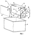
- the storage compartment 10 according to the invention shown in FIG. 1 is a card compartment for storage of maps and road maps or similar flat objects in provided a motor vehicle.
- the storage compartment 10 can, for example, in a door panel integrate.
- the storage compartment 10 is for Intended to be inserted into a box-shaped, larger container 11 open at the top, which in turn can be accommodated in a motor vehicle, not shown.
- the storage compartment 10 has a base part 12 with a side wall 14, of the two of which The ends of two shorter end walls 16 protrude at right angles.
- the side wall 14 forms one also designated 14 system for the storage, not shown Maps and streets.
- the storage compartment 10 has a plate-shaped, rectangular pressure element 18, the laterally projecting guide pin 20, 22nd has near its upper and lower edges. With the upper guide pin 20 the pressure element 18 is slidably guided in guideways 24, which act as slots formed and attached in an upper region of the end walls 16 of the base part 12 are.
- the guideways 24 initially run approximately in an arc shape at right angles away from the side wall 14 and end at a distance from the side wall 14 into a section parallel to the bottom wall 14 perpendicularly downwards about.
- This end section of the guideways 24 has the reference number 26 referred to, in the assembled state of the storage compartment 10 are the upper Guide pin 20 of the pressure element 18 in the guide tracks 24 and are in this slidably guided.
- the lower guide pins 22 of the pressure element 18 reach through in the assembled state of the storage compartment 10 slots 28 which in lower part of the end walls 16 of the base part 12 are attached.
- At the bottom Guide pin 22 is the pressure element 18 with a pair of pivot levers 30 a circular arc section around pivot pin 32 slidably guided, wherein the pivot pins 32 projecting outward on the outside of the end walls 16 are arranged below the guideways 24 and near the side wall 14.
- the Slots 28 in the lower region of the end walls 16 run in a circular arc around the Pivot pin 32 around.
- the pressure element 18 with the lower ones Guide pin 22 slidably in the slots 28 in the lower region of the end walls 16 to lead.
- the slots 28 have in the lower Area of the end walls 16 no guiding function, they have only the purpose the passage of the lower guide pin 22 through the end walls 16 of the base part 12 to enable the pressure element 18 on its lower guide pin 22 on the outer sides of the end walls 16 of the base part 12 with those arranged there To guide swivel levers 30 movably.
- the storage compartment 10 has two pressure spring elements 34, which are the pressure element 18 press against the side wall 14.
- pressure spring elements 34 are torsion coil springs 34 with a short and a long leg 36, 38 used as pressure spring elements 34.
- the torsion coil springs 34 are arranged on the outer sides of the end walls 16 of the base part 12, the torsion coil springs 34 are placed on short, tubular spring seats 40, which on the outside of the end walls 16 are attached. With her short legs 16 the torsion coil springs 16 are supported on a stiffening rib 42 of the end walls 16 from, with the long legs 38 engage the torsion coil springs 34 the upper guide pin 20 of the pressure element 18 and press it in Direction of side wall 14.
- a rectangular recess 44 is made, in which the pressure element 18 lies flush flush in a non-use position, as in FIG Figure 2 shown.
- the recess 44 has a handle opening 46 in the middle of its top.
- the storage compartment 10 is in the illustrated embodiment as an insert provided for the larger container 11. It will be with the side wall 14 of his Base part 12 inserted into a side wall of the container 11, the end walls 16 of the base part 12 of the storage compartment 10 on adjacent Side walls of the container 11 abut.
- the function of the storage compartment 10 is described below with reference to FIG Figures 2 to 4 explained.
- For inserting maps or street maps in the storage compartment 10 is the plate-shaped pressure element 18 through the handle opening 46 in the base part 12 gripped and against the spring force of the torsion coil springs 34 from the side wall 14 away from the position shown in FIG. 3 to the position shown in FIG. 4, position moved from the side wall 14.
- the pressure element 18 above in the guideways 24 and below with the pivot levers 30 flexibly guided.
- the pressure element 18 moves from that shown in FIG shown, non-use position up to the intermediate position shown in Figure 3 shortly before the transition into the vertically downward end sections 26 of the Guideways 24, the pressure element 18 is moved parallel to the side wall 14.
- the pressure element 18 is turned vertically downward extending end portions 26 of the guideways 24 pressed, a lower, guided on the lower guide pin 22 with the pivot levers 30 of the pressure element 18 a short distance back in the direction of the side wall 14 emotional.
- the pressure element 18 is inclined, as can be seen in FIG. 4.
- Pressure element 18 spaced from the side wall 14 end position
- Pressure element 18 is the upper guide pin 20 in the end portions 26 of the guideways 24, these end sections 26 of the guideways 24 approximately perpendicular to a direction of action of the torsion coil springs 34 run and thereby the pressure element 18 in the spaced from the side wall 14 Hold the end position against the force of the torsion coil springs 34.
- guideways 24 form one also designated 26 holding device for the pressure element 18 in the of the side wall 14 spaced end position.
- the pressure element 18 can in this Release the end position and you can insert the maps or street maps placed in the storage compartment 10 between the pressure element 18 and the side wall 14 become. Then the pressure element 18 is raised briefly, so that its upper guide pin 20 from the vertical end portions 26 of the Guideways 24 come out. The pressure element 18 is then the Torsion coil springs 34 against those not shown, inserted into the storage compartment 10 Maps and maps pressed and holds them between the Pressure element 18 and the side wall 14. Since the pressure element 18 in its in Figure 4 shown, spaced from the side wall 14 end position automatically remains and can be released is the insertion of the maps or street maps easily possible with one hand.
Landscapes
- Engineering & Computer Science (AREA)
- Mechanical Engineering (AREA)
- Vehicle Step Arrangements And Article Storage (AREA)
- Conveying Record Carriers (AREA)
- Electrically Operated Instructional Devices (AREA)
- Push-Button Switches (AREA)
- Acyclic And Carbocyclic Compounds In Medicinal Compositions (AREA)
Abstract
Description
- Figur 1
- eine Explosionsdarstellung eines Ablagefachs gemäß der Erfindung in Perspektive; und
- Figuren 2 bis 4
- das Ablagefach aus Figur 1 in zusammengesetztem Zustand in unterschiedlichen Stellungen in einer Querschnittsdarstellung.
Claims (7)
- Ablagefach (Kartenfach) zur Aufbewahrung flächiger Gegenstände in einem Kraftwagen, mit einer Anlage (14) für die flächigen Gegenstände, mit einem Andruckelement (18), mit einer Führung (24, 26, 30) für das Andruckelement (18), die das Andruckelement (18) zwischen einer der Anlage (14) nahen oder an der Anlage (14) anliegenden Stellung und einer von der Anlage (14) beabstandeten Stellung hin- und herbeweglich führt, mit einem Andruckfederelement (34), welches das Andruckelement (18) in Richtung der Anlage (14) drückt, und mit einer Halteeinrichtung (20, 26), die das Andruckelement (18) gegen die Kraft des Andruckfederelements (34) lösbar in der von der Anlage (14) beabstandeten Stellung hält.
- Ablagefach nach Anspruch 1, dadurch gekennzeichnet, dass das Ablagefach (10) eine Aussparung (42) aufweist, in der das Andruckelement (18) in der an der Anlage (14) anliegenden Stellung einliegt.
- Ablagefach nach Anspruch 1, dadurch gekennzeichnet, dass die Führung (24, 26, 30) das Andruckelement (18) in etwa parallel verschieblich führt.
- Ablagefach nach Anspruch 3, dadurch gekennzeichnet, dass die Führung eine Schiebeführung mit Führungsbahnen (24, 26), mit denen das Andruckelement (18) verschieblich geführt ist, aufweist.
- Ablagefach nach Anspruch 3, dadurch gekennzeichnet, dass die Führung eine Schwenkhebelführung (30) aufweist.
- Ablagefach nach Anspruch 1, dadurch gekennzeichnet, dass die Führung (24, 26) für das Andruckelement (18) zugleich die Halteeinrichtung (20, 26) bildet, die das Andruckelement (18) gegen die Kraft des Andruckfederelements (34) lösbar in der von der Anlage (14) beabstandeten Stellung hält.
- Ablagefach nach Anspruch 4 und 6, dadurch gekennzeichnet, dass die Führungsbahnen (24, 26) in Abstand von der Anlage (14) so verlaufen, dass sie das Andruckelement (18) in der von der Anlage (14) beabstandeten Stellung gegen eine Verschiebung durch das Andruckfederelement (34) sperren.
Applications Claiming Priority (2)
| Application Number | Priority Date | Filing Date | Title |
|---|---|---|---|
| DE19942355 | 1999-09-04 | ||
| DE19942355A DE19942355A1 (de) | 1999-09-04 | 1999-09-04 | Ablagefach (Kartenfach) |
Publications (3)
| Publication Number | Publication Date |
|---|---|
| EP1080992A2 true EP1080992A2 (de) | 2001-03-07 |
| EP1080992A3 EP1080992A3 (de) | 2002-11-27 |
| EP1080992B1 EP1080992B1 (de) | 2004-05-19 |
Family
ID=7920885
Family Applications (1)
| Application Number | Title | Priority Date | Filing Date |
|---|---|---|---|
| EP00116583A Expired - Lifetime EP1080992B1 (de) | 1999-09-04 | 2000-08-01 | Ablagefach (Kartenfach) |
Country Status (7)
| Country | Link |
|---|---|
| US (1) | US6554153B1 (de) |
| EP (1) | EP1080992B1 (de) |
| JP (1) | JP3377506B2 (de) |
| KR (1) | KR20010050121A (de) |
| AT (1) | ATE267099T1 (de) |
| DE (2) | DE19942355A1 (de) |
| ES (1) | ES2219234T3 (de) |
Family Cites Families (8)
| Publication number | Priority date | Publication date | Assignee | Title |
|---|---|---|---|---|
| AT110250B (de) * | 1926-09-02 | 1928-07-25 | Franz Klusacek | Vorrichtung zum Aufbewahren von Lebensmitteln. |
| US2392604A (en) * | 1944-03-04 | 1946-01-08 | Mallory Clyde | Receptacle for loose discarded materials |
| FR2239109A5 (en) * | 1973-07-25 | 1975-02-21 | Bichon Jacques | Plastic container for displaying flat packets - plate attached to elastic bands moves packets to front access opening |
| US4915273A (en) * | 1989-02-24 | 1990-04-10 | Allen John M | Bow and gun holders for offroad vehicles |
| DE29603661U1 (de) * | 1996-02-29 | 1996-05-09 | Adam Opel AG, 65428 Rüsselsheim | Fahrzeugsitz-Rückenlehne |
| DE19753647A1 (de) * | 1997-12-03 | 1999-07-15 | Rido Prof Busse | Nachrüstbare Halterung mit einer Aufnahme für Bücher, Karten und dergleichen |
| DE29817147U1 (de) * | 1998-09-24 | 1998-12-10 | Toleimat, Adel, 69198 Schriesheim | Halte-, Aufbewahrungs- und Schauvorrichtung für Kraftfahrzeugausweise, -berechtigungskarten u.ä. |
| JP4239285B2 (ja) * | 1999-04-05 | 2009-03-18 | トヨタ紡織株式会社 | ドアトリム用ポケット |
-
1999
- 1999-09-04 DE DE19942355A patent/DE19942355A1/de not_active Withdrawn
-
2000
- 2000-08-01 EP EP00116583A patent/EP1080992B1/de not_active Expired - Lifetime
- 2000-08-01 ES ES00116583T patent/ES2219234T3/es not_active Expired - Lifetime
- 2000-08-01 DE DE50006466T patent/DE50006466D1/de not_active Expired - Fee Related
- 2000-08-01 AT AT00116583T patent/ATE267099T1/de not_active IP Right Cessation
- 2000-08-18 KR KR1020000047824A patent/KR20010050121A/ko not_active Withdrawn
- 2000-08-30 US US09/650,835 patent/US6554153B1/en not_active Expired - Fee Related
- 2000-09-01 JP JP2000265448A patent/JP3377506B2/ja not_active Expired - Fee Related
Also Published As
| Publication number | Publication date |
|---|---|
| EP1080992B1 (de) | 2004-05-19 |
| US6554153B1 (en) | 2003-04-29 |
| JP2001097130A (ja) | 2001-04-10 |
| DE50006466D1 (de) | 2004-06-24 |
| EP1080992A3 (de) | 2002-11-27 |
| JP3377506B2 (ja) | 2003-02-17 |
| ATE267099T1 (de) | 2004-06-15 |
| ES2219234T3 (es) | 2004-12-01 |
| DE19942355A1 (de) | 2001-03-08 |
| KR20010050121A (ko) | 2001-06-15 |
Similar Documents
| Publication | Publication Date | Title |
|---|---|---|
| DE69603063T2 (de) | Anordnung einer Platte in einer kastenförmigen Vorrichtung eines Kraftfahrzeugs | |
| DE19646645C2 (de) | Behälter | |
| DE19824248A1 (de) | Abdeckung mit einer Mehrzahl von Flächenelementen, ihre Verwendung, sowie Innenausstattungsteil eines Fahrzeuges hiermit | |
| DD298734A5 (de) | Fuehrung fuer einen auszug, einen schubkasten od. dgl. | |
| DE102012204160A1 (de) | Transportbox | |
| DE602004000781T2 (de) | Durch zweimaliges Drücken betätigte Schliessvorrichtung | |
| EP0841213B1 (de) | Fahrzeugascher | |
| DE102012109751A1 (de) | Auszugführung eines ausziehbaren Möbelteils und Möbel | |
| DE102005017565B4 (de) | Haltevorrichtung | |
| DE202018104659U1 (de) | Auszugssperre und Anordnung einer Auszugssperre in einem Möbel | |
| DE3534098A1 (de) | Ablagekasten mit stauraum | |
| DE202009005121U1 (de) | Ausstoßvorrichtung einer Ausziehführung und Ausziehführung | |
| DE29805365U1 (de) | Mehrzweckkoffer | |
| DE9302215U1 (de) | An einer Begrenzungswand einer Abstell-/Ablagefläche anzubringender positionierbarer Teiler für diese Fläche | |
| DE102021114154B3 (de) | Ablage für ein fahrzeug | |
| EP1080992A2 (de) | Ablagefach (Kartenfach) | |
| DE102015211295A1 (de) | Vorrichtung zum Sichern von Ladegut in einem Laderaum eines Kraftfahrzeugs | |
| DE202010006291U1 (de) | Verriegelungseinrichtung | |
| DE19922847A1 (de) | Verschluß für einen Ausschnitt an einem Fahrzeugteil, insbesondere an einer Stoßstange | |
| DE20217975U1 (de) | Einzugsvorrichtung für Schubladen | |
| DE10054322B4 (de) | Dachkonstruktion, insbesondere für Kraftfahrzeuge, mit einem Dachausschnitt und diesem zugeordneten Deckeln | |
| DE202004015416U1 (de) | Bodenführung für ein seitlich verschiebbares Trennelement | |
| DE3823150C2 (de) | ||
| EP0559861B1 (de) | Eintreibgerät mit magazinverschluss | |
| DE102008034482A1 (de) | Halter für Getränkebehälter |
Legal Events
| Date | Code | Title | Description |
|---|---|---|---|
| PUAI | Public reference made under article 153(3) epc to a published international application that has entered the european phase |
Free format text: ORIGINAL CODE: 0009012 |
|
| AK | Designated contracting states |
Kind code of ref document: A2 Designated state(s): AT BE CH CY DE DK ES FI FR GB GR IE IT LI LU MC NL PT SE |
|
| AX | Request for extension of the european patent |
Free format text: AL;LT;LV;MK;RO;SI |
|
| PUAL | Search report despatched |
Free format text: ORIGINAL CODE: 0009013 |
|
| AK | Designated contracting states |
Kind code of ref document: A3 Designated state(s): AT BE CH CY DE DK ES FI FR GB GR IE IT LI LU MC NL PT SE |
|
| AX | Request for extension of the european patent |
Free format text: AL;LT;LV;MK;RO;SI |
|
| RIC1 | Information provided on ipc code assigned before grant |
Free format text: 7B 60R 7/04 A, 7B 60R 7/08 B |
|
| 17P | Request for examination filed |
Effective date: 20030320 |
|
| 17Q | First examination report despatched |
Effective date: 20030516 |
|
| AKX | Designation fees paid |
Designated state(s): AT BE CH CY DE DK ES FI FR GB GR IE IT LI LU MC NL PT SE |
|
| GRAP | Despatch of communication of intention to grant a patent |
Free format text: ORIGINAL CODE: EPIDOSNIGR1 |
|
| GRAS | Grant fee paid |
Free format text: ORIGINAL CODE: EPIDOSNIGR3 |
|
| GRAA | (expected) grant |
Free format text: ORIGINAL CODE: 0009210 |
|
| AK | Designated contracting states |
Kind code of ref document: B1 Designated state(s): AT BE CH CY DE DK ES FI FR GB GR IE IT LI LU MC NL PT SE |
|
| PG25 | Lapsed in a contracting state [announced via postgrant information from national office to epo] |
Ref country code: IE Free format text: LAPSE BECAUSE OF FAILURE TO SUBMIT A TRANSLATION OF THE DESCRIPTION OR TO PAY THE FEE WITHIN THE PRESCRIBED TIME-LIMIT Effective date: 20040519 Ref country code: FI Free format text: LAPSE BECAUSE OF FAILURE TO SUBMIT A TRANSLATION OF THE DESCRIPTION OR TO PAY THE FEE WITHIN THE PRESCRIBED TIME-LIMIT Effective date: 20040519 Ref country code: CY Free format text: LAPSE BECAUSE OF FAILURE TO SUBMIT A TRANSLATION OF THE DESCRIPTION OR TO PAY THE FEE WITHIN THE PRESCRIBED TIME-LIMIT Effective date: 20040519 |
|
| REG | Reference to a national code |
Ref country code: GB Ref legal event code: FG4D Free format text: NOT ENGLISH |
|
| REG | Reference to a national code |
Ref country code: CH Ref legal event code: EP |
|
| REG | Reference to a national code |
Ref country code: IE Ref legal event code: FG4D Free format text: GERMAN |
|
| REF | Corresponds to: |
Ref document number: 50006466 Country of ref document: DE Date of ref document: 20040624 Kind code of ref document: P |
|
| PGFP | Annual fee paid to national office [announced via postgrant information from national office to epo] |
Ref country code: GB Payment date: 20040728 Year of fee payment: 5 |
|
| PG25 | Lapsed in a contracting state [announced via postgrant information from national office to epo] |
Ref country code: LU Free format text: LAPSE BECAUSE OF NON-PAYMENT OF DUE FEES Effective date: 20040801 Ref country code: AT Free format text: LAPSE BECAUSE OF NON-PAYMENT OF DUE FEES Effective date: 20040801 |
|
| PGFP | Annual fee paid to national office [announced via postgrant information from national office to epo] |
Ref country code: NL Payment date: 20040803 Year of fee payment: 5 |
|
| PGFP | Annual fee paid to national office [announced via postgrant information from national office to epo] |
Ref country code: SE Payment date: 20040806 Year of fee payment: 5 |
|
| PGFP | Annual fee paid to national office [announced via postgrant information from national office to epo] |
Ref country code: FR Payment date: 20040810 Year of fee payment: 5 |
|
| PG25 | Lapsed in a contracting state [announced via postgrant information from national office to epo] |
Ref country code: GR Free format text: LAPSE BECAUSE OF FAILURE TO SUBMIT A TRANSLATION OF THE DESCRIPTION OR TO PAY THE FEE WITHIN THE PRESCRIBED TIME-LIMIT Effective date: 20040819 Ref country code: DK Free format text: LAPSE BECAUSE OF FAILURE TO SUBMIT A TRANSLATION OF THE DESCRIPTION OR TO PAY THE FEE WITHIN THE PRESCRIBED TIME-LIMIT Effective date: 20040819 |
|
| PGFP | Annual fee paid to national office [announced via postgrant information from national office to epo] |
Ref country code: ES Payment date: 20040825 Year of fee payment: 5 |
|
| PG25 | Lapsed in a contracting state [announced via postgrant information from national office to epo] |
Ref country code: MC Free format text: LAPSE BECAUSE OF NON-PAYMENT OF DUE FEES Effective date: 20040831 Ref country code: LI Free format text: LAPSE BECAUSE OF NON-PAYMENT OF DUE FEES Effective date: 20040831 Ref country code: CH Free format text: LAPSE BECAUSE OF NON-PAYMENT OF DUE FEES Effective date: 20040831 Ref country code: BE Free format text: LAPSE BECAUSE OF NON-PAYMENT OF DUE FEES Effective date: 20040831 |
|
| GBT | Gb: translation of ep patent filed (gb section 77(6)(a)/1977) |
Effective date: 20040831 |
|
| ET | Fr: translation filed | ||
| REG | Reference to a national code |
Ref country code: ES Ref legal event code: FG2A Ref document number: 2219234 Country of ref document: ES Kind code of ref document: T3 |
|
| REG | Reference to a national code |
Ref country code: IE Ref legal event code: FD4D |
|
| BERE | Be: lapsed |
Owner name: BAYERISCHE MOTOREN WERKE A.G. Effective date: 20040831 Owner name: FISCHERWERKE ARTUR FISCHER G.M.B.H. & CO. KG Effective date: 20040831 |
|
| PLBE | No opposition filed within time limit |
Free format text: ORIGINAL CODE: 0009261 |
|
| STAA | Information on the status of an ep patent application or granted ep patent |
Free format text: STATUS: NO OPPOSITION FILED WITHIN TIME LIMIT |
|
| REG | Reference to a national code |
Ref country code: CH Ref legal event code: PL |
|
| 26N | No opposition filed |
Effective date: 20050222 |
|
| PG25 | Lapsed in a contracting state [announced via postgrant information from national office to epo] |
Ref country code: IT Free format text: LAPSE BECAUSE OF NON-PAYMENT OF DUE FEES Effective date: 20050801 Ref country code: GB Free format text: LAPSE BECAUSE OF NON-PAYMENT OF DUE FEES Effective date: 20050801 |
|
| PG25 | Lapsed in a contracting state [announced via postgrant information from national office to epo] |
Ref country code: SE Free format text: LAPSE BECAUSE OF NON-PAYMENT OF DUE FEES Effective date: 20050802 Ref country code: ES Free format text: LAPSE BECAUSE OF NON-PAYMENT OF DUE FEES Effective date: 20050802 |
|
| PG25 | Lapsed in a contracting state [announced via postgrant information from national office to epo] |
Ref country code: NL Free format text: LAPSE BECAUSE OF NON-PAYMENT OF DUE FEES Effective date: 20060301 |
|
| EUG | Se: european patent has lapsed | ||
| GBPC | Gb: european patent ceased through non-payment of renewal fee |
Effective date: 20050801 |
|
| PG25 | Lapsed in a contracting state [announced via postgrant information from national office to epo] |
Ref country code: FR Free format text: LAPSE BECAUSE OF NON-PAYMENT OF DUE FEES Effective date: 20060428 |
|
| NLV4 | Nl: lapsed or anulled due to non-payment of the annual fee |
Effective date: 20060301 |
|
| REG | Reference to a national code |
Ref country code: FR Ref legal event code: ST Effective date: 20060428 |
|
| REG | Reference to a national code |
Ref country code: ES Ref legal event code: FD2A Effective date: 20050802 |
|
| PGFP | Annual fee paid to national office [announced via postgrant information from national office to epo] |
Ref country code: DE Payment date: 20070530 Year of fee payment: 8 |
|
| BERE | Be: lapsed |
Owner name: *BAYERISCHE MOTOREN WERKE A.G. Effective date: 20040831 Owner name: FISCHERWERKE ARTUR *FISCHER G.M.B.H. & CO. K.G. Effective date: 20040831 |
|
| PG25 | Lapsed in a contracting state [announced via postgrant information from national office to epo] |
Ref country code: PT Free format text: LAPSE BECAUSE OF NON-PAYMENT OF DUE FEES Effective date: 20041019 |
|
| PG25 | Lapsed in a contracting state [announced via postgrant information from national office to epo] |
Ref country code: DE Free format text: LAPSE BECAUSE OF NON-PAYMENT OF DUE FEES Effective date: 20090303 |