EP1079675A2 - Verfahren zur Erzeugung einer Leitungsstruktur mit wenigstens einem Kabelbündel - Google Patents
Verfahren zur Erzeugung einer Leitungsstruktur mit wenigstens einem Kabelbündel Download PDFInfo
- Publication number
- EP1079675A2 EP1079675A2 EP00116085A EP00116085A EP1079675A2 EP 1079675 A2 EP1079675 A2 EP 1079675A2 EP 00116085 A EP00116085 A EP 00116085A EP 00116085 A EP00116085 A EP 00116085A EP 1079675 A2 EP1079675 A2 EP 1079675A2
- Authority
- EP
- European Patent Office
- Prior art keywords
- line
- lines
- cable
- routes
- types
- Prior art date
- Legal status (The legal status is an assumption and is not a legal conclusion. Google has not performed a legal analysis and makes no representation as to the accuracy of the status listed.)
- Withdrawn
Links
Images

Classifications
-
- B—PERFORMING OPERATIONS; TRANSPORTING
- B60—VEHICLES IN GENERAL
- B60R—VEHICLES, VEHICLE FITTINGS, OR VEHICLE PARTS, NOT OTHERWISE PROVIDED FOR
- B60R16/00—Electric or fluid circuits specially adapted for vehicles and not otherwise provided for; Arrangement of elements of electric or fluid circuits specially adapted for vehicles and not otherwise provided for
- B60R16/02—Electric or fluid circuits specially adapted for vehicles and not otherwise provided for; Arrangement of elements of electric or fluid circuits specially adapted for vehicles and not otherwise provided for electric constitutive elements
- B60R16/0207—Wire harnesses
-
- G—PHYSICS
- G06—COMPUTING OR CALCULATING; COUNTING
- G06F—ELECTRIC DIGITAL DATA PROCESSING
- G06F30/00—Computer-aided design [CAD]
- G06F30/10—Geometric CAD
- G06F30/18—Network design, e.g. design based on topological or interconnect aspects of utility systems, piping, heating ventilation air conditioning [HVAC] or cabling
-
- G—PHYSICS
- G06—COMPUTING OR CALCULATING; COUNTING
- G06F—ELECTRIC DIGITAL DATA PROCESSING
- G06F2113/00—Details relating to the application field
- G06F2113/16—Cables, cable trees or wire harnesses
Definitions
- the invention relates to a method for generating a Line structure with at least one cable bundle.
- connections are often through separately manufactured cable bundles, which subsequently used in the mechanical structure and with the device Connections are connected.
- the mechanical structure is inclusive the positions of the devices predefined and the management structure is fitted into this specification, whereby the logical connection plan for the electrical system specifies the connections in detail.
- the object of the present invention is a method to specify a line structure, which under Use of a data processing system to generate a complete management structure.
- the simple creation is essential to the invention a management structure through common presentation of mechanical structure and connecting lines and on the other hand, the examination of a draft management structure possible collisions (incompatibilities) with given Restrictions, especially restrictions on electrical Systems.
- Such restrictions can in particular due to intolerance of certain lines the coupling of interference, maximum signal attenuation along a line etc.
- This collision check can advantageously be completely within the design phase done on the data processing system, so that when a collision is detected, it is displayed and the Draft can be modified. Is of particular advantage while keeping the restrictive requirements relatively simple be and for defining the routes as well the assignment of connecting lines to such line routes no complex expert knowledge to be programmed needs because these measures on the controls are feasible.
- the former are particularly due to electrical parameters especially with regard to electromagnetic coupling behavior, Characterized signal type etc., while the latter the physical shape with cross-section, curvature radius restriction etc. is specified.
- the one from which the display of the mechanical structure and the connecting lines / line structure controlling main program assignments made in a separate program or program module are then fed back into the main program and continue there or in another program module processed. For example, after assigning a specific Cable types, e.g. B. a cable with shielding Sheathing to a connecting line of a line section be checked again to see if the minimum bend radius of the assigned cable type with changes of direction is compatible within the route section.
- a specific Cable types e.g. B. a cable with shielding Sheathing to a connecting line of a line section be checked again to see if the minimum bend radius of the assigned cable type with changes of direction is compatible within the route section.
- such a main program can be a CAD program for the design of the mechanical structure and a another program a design program for the logical Be a management plan.
- the main program one of the CAD program for the design of the mechanical Structure-separated program with CAD functions in reduced Scope provided. Then there is no interference in that basic CAD program required and the main program more universally applicable.
- the functions of the above program called the main program can also in the basic CAD program for mechanical Be integrated into the design, e.g. B. as an additional module or plug-in.
- Definitions and assignments when designing the management structure can also change the mechanical structure itself and influence, for example in the form of fasteners for cable bundles or in the form of wall openings to carry a cable bundle or to insert in the Course of a route. Such changes are then again to check for mechanical permissibility.
- Changes in the management structure draft can be a new one Trigger collision according to another criterion, what at several separate program modules for multiple data exchange dialog can lead to a user acceptable evaluated and confirmed draft is available, which one for the production of the line structure in the form of a or several cable bundles is used.
- the one when creating line structure generated from the design is preferred in the description of the mechanical structure taken over, so that with a possible later change the mechanical structure, the presence of the line structure can be taken into account. Changes can also be made in the course of the connecting lines, especially in Form of connecting elements as separation points with more precise Contact assignment in the logical wiring diagram of the electrical Systems are taken over.
- the establishment of routes in the preferably as 3D display executed display goes according to an advantageous Embodiment from an initial mapping the connecting lines between connecting elements the devices as straight lines of shortest connection paths without Consideration of the mechanical structure.
- the fasteners on the devices can both by Art and position of the device in their fixed position or in their position on the device, possibly still by the user in the display be positionable.
- Line routes are preferably defined in Form of adjoining line sections with uniform management grouping within each Section.
- Route sections can preferably by specifying section endpoints in the display the mechanical structure and for example are guided in the course of deflection points.
- the cables are routed on direct way, taking into account finite Cable bends at deflection points and connection points realistic course is ensured and cable bends for example by one to the 2nd derivative of the Guidance steady path are represented.
- the deflection radii may have both mechanical design limitations as well as restrictions on the cable types of the route section assigned connection routes his.
- Line route section endpoints can in particular be attached be for cable end points on the devices, for connection points a cable bundle and for separation points with Fasteners. Since the finished cable bundle through the Tie together u. U. are hardly flexible in themselves and around to rule out later inadmissible cable bends during installation, become deflections and extensions according to bending radii and angles in the design and the cable bundles manufactured with these values.
- a particularly advantageous method for carrying out a automated collision checking, d. H. rating not by the user but by pre-programmed Procedures provides for different criteria for certain Define individual characteristics and exclusion links to be specified in the manner of a matrix table. For the The design of a cable bundle can then be based on the line assignment to a route section and based on the specifications to cable types and signal types from the definition of the electrical system to meet individual criteria easily checked and from the given exclusion links be recognized whether there is an intolerance. Possibly. can use the criteria and / or lines involved in the event of a collision notice.
- the collision check can thus be schematized in a simple manner and especially automatically without rating be performed by the user.
- several Cable types such as particularly sensitive to radiation or particularly radiating lines, if necessary, taking into account a rough frequency range division, be specified and individual lines of the electrical system as one of the line types become.
- the collision criteria are then to the respective line groups of a cable bundle or a line section of a branched cable bundle applied. It is particularly advantageous that the specification of Line types and / or the pre-definition of collision criteria regardless of a specific pipe system or bundles of cables can be done and the process is special inexpensive to run on a data processing system is.
- Such predefinitions can be based on one-off determination then without further modification different cable bundles are used and for example for a whole group of objects and / or within of a project apply to all objects or globally.
- a and the same program structure is also a simple one Adaptation to special project requirements through redefinition of line types and criteria possible.
- the collision check can be carried out in addition to the electromagnetic check Compatibility of combined lines advantageously other criteria, especially the Checking cable lengths, signal attenuation between two devices, from bend radii along the route, of mechanical strengths for cable ducts wall openings with or without plug connection, of exceeding permissible cross sections of Attachment points etc. include.
- a recognized incompatibility within a cable bundle or a portion thereof causes generation a collision signal, which preferably information about the type of intolerance and / or involved Includes lines in detail and for example through a special display form (e.g. color, flashing Display, marking) in the representation of the structure with the routes and / or in a list of the individual Lines is issued.
- a collision signal which preferably information about the type of intolerance and / or involved Includes lines in detail and for example through a special display form (e.g. color, flashing Display, marking) in the representation of the structure with the routes and / or in a list of the individual Lines is issued.
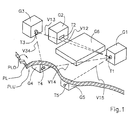
- FIG Top side PLO and bottom side PLU of one assumed to be continuous, in the figure cut plate PL several devices G1 to G6 arranged at fixed positions, the devices G1 to G6 belong to an electrical system should and electrically via connecting lines Vij are interconnected.
- the structure shown is greatly simplified and serves compared to a real construction merely an illustration of the basic procedure according to the invention.
- connecting elements T1 to T5 are provided, which with corresponding counterparts to be generated Management structure, especially in Form of plug-in connections, but also through clamp connections, Solder connections etc. can be formed.
- One device can also have several separate connecting elements Tn may be provided.
- fasteners T1 to T5 have a limited number of types Available, which depends on the type and number of electrical Connections for the individual connecting element T1 to T5 is further restricted.
- the position of a connecting element T1 to T5 on one Device G1 to G6 can either by the design of the device G1 to G6 specified or still limited by the user be selectable. Positioning by the user can be used in a conventional manner by direct position specification via the keyboard, via 2D input devices (mouse, Trackball) or 3D input devices, preferably under illustration a movable marker (cursor) on the Display. If there are still a plurality of element types is selectable for the user, the selection can on the basis of a type list and / or on the basis of illustrations.
- connection elements T1 to T5 can advantageously also the multi-core connecting lines Vij on the device side in connection elements T1 to T5, preferably with clear contact assignment of the individual cores. It is also the assignment of cables and / or individual wires to a connecting element T1 to T5 possible by the user.
- connection lines Vij Given the assignment of the connecting lines Vij to the device side Connection elements or connecting elements T1 to T5 can equate one shown in the display Connection element Tn with one in the logical line plan of the electrical system existing connection element Tn or after assigning cables or wires to one displayed connection element Tn automatically using the data of the logical line plan already a representation of the connecting lines Vij in the display of the mechanical structure take place, preferably in the form of straight lines between the connecting elements connected by the connecting lines Vij Tn of the various devices G1 to G6.
- the Connection lines Vij then form in this display form shortest paths between two connected connection elements T1 with T3 or T1 with T2 without considering the mechanical Construction, which such shortest connection paths in the Normally not allowed.
- the connecting lines can be in the display advantageously in color and / or shape be presented in a distinguishable manner. In the picture 1, the connecting lines Vij by interrupted, Dotted lines are shown in hidden areas.
- the user can define routes in the display preferably the size of the section shown as well as the direction of view of the object using the keyboard and / or input device can be varied. You can do this for example end points for line sections on surfaces the mechanical structure shown and positioned Line path sections defined between two such end points become. Line sections are generally between two endpoints as just assumed, but can by positioning deflection points in several to each other Subsequent parts can be divided and an angled Form connection, advantageously from from the start, the routing of the lines is continuous, as already described, he follows. Curved path elements can also be selected his. At the deflection points u. U. bending radii definable be, but also automatically for a finished Cable bundles on the minimum for the integrated cables Bending radius can be adjusted.
- connections through a surface that is closed by the design of the mechanical structure represent a special case for the determination of line routes.
- the user can use a cursor to determine a position for a surface opening, through which either a cable bundle can be passed or to which can be attached in the form of a plug connection or the like.
- the attachment of a plug-in connection permanently installed in the opening with plug contacts present on both sides of the surface thereby broken through is to be preferred to a cable lead-through through the opening if the cable bundle section to be carried out is longer and / or branched and therefore difficult to handle.
- a plug connection is required if the surface fulfills an essential separating function between two rooms and is to be designed, for example, to be pressure-tight or explosion-proof.
- a separation point can also otherwise be provided in a line routing in order to divide an extensive structure into several cable bundles of less complexity.
- this does not need to be defined a priori in terms of the specific type, but can be inserted as a separation point per se (generic connection element), which is later assigned a specific type.
- the definition of a surface opening is to be checked for mechanical permissibility, which can lead to a collision message, for example, and which the user can then simply correct by moving the opening position to a permissible position.
- the mechanical admissibility can be checked in the running program of the display or by data exchange in a separate program or program module, which can be, in particular, the CAD program for the design of the mechanical structure.
- Fig. 2 shows an intermediate stage in the definition of Line structure, wherein a first line section B1 between end points A1A and A1B, a second line section B2 between endpoints B2A and B2B and a third Line route section B3 defined between end points B3A and B3B are. Furthermore, a separation point is a connector WS set in an inserted opening of the plate PL.
- the first line path section B1 is at a deflection point U1 angled.
- the three route sections B1, B2 and B3 meet at a branch point, in the endpoints A1B of the first, B2A of the second and B3A of the third line section B1, B2 or B3 coincide.
- the third route section B3 leads from the Branch point to the connecting element WS.
- Connection lines Vij according to FIG. 1 can also be assigned to the line path sections B1, B2, B3 immediately after they have been defined, which in turn can be carried out by the user via the usual operating elements. The assignment can also be made for only a part of the wires of a multi-core connecting line Vij. With the assignment of a connecting line Vij to a line route section B1, B2 or B3, the representation is advantageously changed automatically such that the symbolic connecting lines Vij no longer between the fixed connection points on the connection elements Tn of the devices G1 to G6, but from these connection points Tn to each one of the end points A1A, A1B,...
- the connecting lines V12, V13, V14 and V15 are assigned to the first line path section B1, with which all connecting lines V12 to V15 starting from the connection element T1 of the device G1 are bundled in this line path section B1 and also from the connection element T1 to the end point A1A of the first line path section B1 can be represented by a single symbolic connecting line Vij.
- the connecting lines V12, V13 and V34 are assigned to the second line path section B2, the connecting lines V14, V15 and V34 to the third line path section B3.
- the three route sections B1 to B3 thus contain different combinations of connecting lines Vij and are therefore also individually on electrical or electromagnetic compatibility of the connected in them Check line types.
- Such a review can in the program or program module, which too the display with the options for determining the route controls and which, for example, the program for Creation of the mechanical structure can be, or in one separate program or module, for example also the program for the design of the logical management plan of the electrical system can be done. It can it, especially in the first case, be advantageous to everyone Change in line routing and line assignment immediately on the compatibility of lines automatically to check, or also, especially in the second Case, a check for compatibility of bundled lines to be carried out only at the instigation of the user.
- an element type can be separated by a The type and number of lines to be connected, if applicable remaining selection can be selected by user, where for example, again on the design of the electrical Management plan can serve a specially designed program.
- a selected element type for the fastener is again a check for admissibility in mechanical Construction checked.
- Connection elements S4 and S5 at the ends of the cable harnesses and that located on the top PLO of the plate PL KBO cable bundles are included in the panel feed-through SWU and SWO elements as well as the one inserted in the panel opening Element WS can be connected to one another and then form the entire electrical line structure.
- the test for electrical and electromagnetic compatibility of a plurality of lines Vij connected in a line path section B1 to B3 advantageously precedes an assignment of the connecting lines Vij or their individual or grouped cores to one of several line types.
- condition> 0 for a line type is fulfilled if at least one line Vij of this type in the examined Bundle of KBO or KBU is present. Also several lines Vij of the same type can be incompatible with each other, for which the condition KX> 1, i.e. two or more Lines Vij of the line type KX is listed.
- a recognized incompatibility can be changed in particular the line assignment to line routes has been eliminated become.
- the particular advantage of the procedure with the pre-definition simple logical and / or numerical conditions lies in the object independence of such a predefinition.
- the test criteria can be modified without modification uniform to all, in the line combination As a rule, different line sections are used become.
- one based on such predefinitions Check because of the simple wording of the conditions for every change in the assignment of lines react promptly to route sections and the Reassess changed assignment almost without delay.
Landscapes
- Engineering & Computer Science (AREA)
- Physics & Mathematics (AREA)
- Theoretical Computer Science (AREA)
- Geometry (AREA)
- General Physics & Mathematics (AREA)
- Computer Hardware Design (AREA)
- Mathematical Analysis (AREA)
- Mathematical Optimization (AREA)
- Pure & Applied Mathematics (AREA)
- Computational Mathematics (AREA)
- Evolutionary Computation (AREA)
- General Engineering & Computer Science (AREA)
- Computer Networks & Wireless Communication (AREA)
- Mechanical Engineering (AREA)
- Installation Of Indoor Wiring (AREA)
- Design And Manufacture Of Integrated Circuits (AREA)
- Electric Cable Installation (AREA)
- Insulated Conductors (AREA)
Abstract
Description
- eine Gesamtstromstärke innerhalb eines Leitungsabschnitts nicht überschritten werden darf.
- Steuer- oder Sensorleitungen zu besonders sensiblen, sicherheitsrelevanten Funktionen nicht mit Leitungen mit bestimmten Signaltypen in einen gemeinsamen Leitungswegabschnitt gebündelt sein dürfen.
- störempfindliche Leitungen nicht zusammen mit Störungen abstrahlenden Leitungen in einem Kabelstrang eines Leitungswegabschnitts zusammengebunden sein dürfen.
- Fig. 1
- eine 3D-Darstellung des mechanischen Aufbaus mit symbolischen Verbindungsleitungen.
- Fig. 2
- den Aufbau nach Fig. 1 mit teilweise festgelegten Leitungswegabschnitten und diesen zugeordneten Verbindungsleitungen.
- Fig. 3
- zwei Kabelbündel als Leitungsstruktur für die Verbindungsleitungen.
Weitere mechanische Änderungen können bei der Festlegung von Leitungswegen beispielsweise auch vom Benutzer positionierbare Befestigungselemente FE sein, für welche gleichfalls die mechanische Zulässigkeit, beispielsweise hinsichtlich der Verbindung mit einer Trägerfläche oder einem anderen Trägerelement des mechanischen Aufbaus durch Schrauben, Nieten, Kleben etc. oder hinsichtlich der Belastbarkeit des mechanischen Verbindungspunkts, der Trägerfläche oder eines anderen Trägerelements überprüft werden kann.
Im in Fig. 2 skizzierten Beispiel sind die Verbindungsleitungen V12, V13, V14 und V15 dem ersten Leitungswegabschnitt B1 zugeordnet, womit alle vom Anschlußelement T1 des Geräts G1 ausgehenden Verbindungsleitungen V12 bis V15 in diesem Leitungswegabschnitt B1 gebündelt sind und auch vom Anschlußelement T1 zum Endpunkt A1A des ersten Leitungswegabschnitts B1 durch eine einzige symbolische Verbindungsleitung Vij repräsentiert sein können. Dem zweiten Leitungswegabschnitt B2 seien die Verbindungsleitungen V12, V13 und V34, dem dritten Leitungswegabschnitt B3 die Verbindungsleitungen V14, V15 und V34 zugeordnet.
| Typ | Beschreibung |
| KE | Störstrahlung emittierend |
| KS | auf Einstrahlung empfindlich |
| KX | Störstrahlung emittierend und auf Einstrahlung |
| KC | empfindlich |
| KA | Leitung mit sensiblem Datentransfer |
| KN | besonders sicherheitsrelevante Signalleitungen |
| ...... | neutrale Leitungen (keine Unverträglichkeiten) |
| . | .......... |
| Typ: | KE | KS | KX | KC | KA | KN | Bedingung |
| >0 | >0 | KE>0 und KS>0 | |||||
| >1 | KX>1 | ||||||
| >0 | >0 | KE>0 und KC>0 | |||||
| >0 | >0 | KE>0 und KA>0 | |||||
| >0 | >0 | KX>0 und KA>0 | |||||
| .............. |
Claims (24)
- Verfahren zur Generierung einer durch ein oder mehrere Kabelbündel (KBO, KBU) gebildeten Leitungsstruktur für ein elektrisches System innerhalb eines mechanischen Aufbaus unter Verwendung einer Datenverarbeitungsanlage, wobei das elektrische System mehrere im mechanischen Aufbau verteilt angeordnete Geräte (G1 bis G6) umfaßt, welche durch die Leitungsstruktur und geräteseitige Verbindungselemente (T1 bis T5 bzw. S1 bis S5) untereinander elektrisch verbunden sind, mit folgenden Merkmalen:a) ein Entwurf für den mechanischen Aufbau wird von der Datenverarbeitungsanlage als Bild dargestellt;b) ein Verbindungsplan des elektrischen Systems wird in Form eines Leitungsdatensatzes mit der Darstellung des mechanischen Aufbaus in der Weise verknüpft, daß Verbindungselemente (T1 bis T5 bzw. S1 bis S5) an den Geräten (G1 bis G6) und Verbindungsleitungen (Vij) zwischen diesen dargestellt werden;c) über Bedieneinrichtungen werden innerhalb der Darstellung des mechanischen Aufbaus Leitungswege festgelegt und Verbindungsleitungen (Vij) solchen Leitungswegen zugeordnet;d) die nach c) gemachten Festlegungen und Zuordnungen werden auf Kollisionen mit vorgegebenen mechanischen und/oder elektrischen Einschränkungen überprüft und Kollisionen werden angezeigt unde) eine Darstellung der Leitungswege mit vollständiger Zuordnung der Verbindungsleitungen (Vij) zu Leitungswegabschnitten (B1 bis B3) wird ggf. nach wiederholter Durchführung der Schritte c) und d) als Entwurf für ein oder mehrere Kabelbündel (KBO, KBU) mit Verbindungselementen (T1 bis T5 bzw. S1 bis S5) weiterverwendet.
- Verfahren nach Anspruch 1, dadurch gekennzeichnet, daß die Festlegung von Leitungswegen die Positionierung von Endpunkten (A1A, A1B bis B3B) von Leitungswegabschnitten (B1 bis B3) umfaßt.
- Verfahren nach Anspruch 1 oder 2, dadurch gekennzeichnet, daß die Festlegung von Leitungswegen die Positionierung von Verzweigungspunkten umfaßt.
- Verfahren nach einem der Ansprüche 1 bis 3, dadurch gekennzeichnet, daß die Festlegung von Leitungswegen die Positionierung von Kabelbefestigungen (FE) umfaßt.
- Verfahren nach einem der Ansprüche 1 bis 4, dadurch gekennzeichnet, daß die Festlegung von Leitungswegen die Positionierung von Umlenkpunkten (U1) innerhalb eines Leitungswegabschnitts (B1) umfaßt.
- Verfahren nach einem der Ansprüche 1 bis 5, dadurch gekennzeichnet, daß die Festlegung von Leitungswegen die Positionierung von Verbindungselementen (T1 bis T5 bzw. S1 bis S5) umfaßt.
- Verfahren nach Anspruch 6, dadurch gekennzeichnet, daß die Positionierung von Verbindungselementen (T1 bis T5, S1 bis S5) die Einfügung von Trennstellen in dem Verlauf von Verbindungsleitungen zwischen Geräten beinhaltet.
- Verfahren nach einem der Ansprüche 1 bis 7, dadurch gekennzeichnet, daß die Festlegung von Leitungswegen als Änderungen in die Beschreibung mechanischen Aufbaus übertragen werden.
- Verfahren nach einem der Ansprüche 1 bis 8, dadurch gekennzeichnet, daß als Trennstellen eingefügte Verbindungselemente (T1 bis T5, S1 bis S5) in die Beschreibung des Verdrahtungsplans des elektrischen Systems übertragen werden.
- Verfahren nach einem der Ansprüche 1 bis 9, dadurch gekennzeichnet, daß die Kollisionsprüfung die elektromagnetische Verträglichkeit von in einem Abschnitt eines Kabelbündels (KBO, KBU) zusammengefaßten Leitungen umfaßt.
- Verfahren nach einem der Ansprüche 1 bis 10, dadurch gekennzeichnet, daß die Kollisionsprüfung die Bestimmung der Signaldämpfung auf Leitungswegen und den Vergleich mit zulässigen Werten umfaßt.
- Verfahren nach einem der Ansprüche 1 bis 11, dadurch gekennzeichnet, daß die Kollisionsprüfung die Erkennung von Leitungsdurchgängen durch Wände ohne Trennstellen umfaßt.
- Verfahren nach einem der Ansprüche 1 bis 12, dadurch gekennzeichnet, daß einzelne oder mehrere der Verfahrensschritte von wenigstens zwei verschiedenen auf der Datenverarbeitungsanlage lauffähigen Programmen ausgeführt werden und Daten zwischen den verschiedenen Programmen über Dateien mit kompatiblen Dateiformaten ausgetauscht werden.
- Verfahren zur Prüfung der elektromagnetischen Verträglichkeit von mehreren in einem Kabelbündel (KBO, KBU) zusammengefaßten Leitungen eines elektrischen Systems mit vorgegebenen elektrischen Eigenschaften, insbesondere nach einem der vorhergehenden Ansprüche, mit folgenden Merkmalen:a) daß mehrere Leitungstypen vordefiniert werden;b) daß Kriterien für Unverträglichkeiten von Leitungstypkombinationen vordefiniert werden;c) daß Leitungen eines Kabelbündels b(KBO, KBU) eines elektrischen Systems jeweils einem der vordefinierten Leitungstypen zugeordnet werden;d) daß in dem Kabelbündel (KBO, KBU) zusammengefaßten Leitungen nach den Kriterien für die Unverträglichkeit von Leitungstypen abgeprüft werden und bei einer erkannten Unverträglichkeit ein Kollisionssignal erzeugt wird.
- Verfahren nach Anspruch 14, dadurch gekennzeichnet, daß die Leitungstypen und die Kriterien für die Unverträglichkeit von Leitungstypen unabhängig von einem konkreten System vordefiniert werden.
- Verfahren nach Anspruch 14 oder 15, dadurch gekennzeichnet, daß bei der Vordefinition der Leitungstypen Signalformen als Klassifizierungsmerkmal berücksichtigt werden.
- Verfahren nach einem der Ansprüche 14 bis 16, dadurch gekennzeichnet, daß bei der Vordefinition von Leitungstypen die elektromagnetische Abstrahlung von Leitungstypen als Klassifizierungsmerkmal berücksichtigt wird.
- Verfahren nach einem der Ansprüche 14 bis 17, dadurch gekennzeichnet, daß bei der Vordefinition von Leitungstypen die Empfindlichkeit von Signalempfängern angeschlossener Geräte (G1 bis G6) gegen Störungen auf der Verbindungsleitung (Vij) als Klassifizierungsmerkmal berücksichtigt wird.
- Verfahren nach einem der Ansprüche 14 bis 18, dadurch gekennzeichnet, daß bei der Vordefinition von Leitungstypen Signalfrequenzbereiche als Klassifizierungsmerkmal berücksichtigt werden.
- Verfahren nach einem der Ansprüche 14 bis 19, dadurch gekennzeichnet, daß die Kriterien für Unverträglichkeiten von Leitungstypkombinationen logische Verknüpfungen für das Vorhandensein von verschiedenen Leitungstypen umfassen.
- Verfahren nach einem der Ansprüche 14 bis 20, dadurch gekennzeichnet, daß bei Kriterien für Unverträglichkeiten von Leitungstypkombinationen die Anzahl von Leitungen desselben Leitungstyps berücksichtigt werden.
- Verfahren nach einem der Ansprüche 14 bis 21, dadurch gekennzeichnet daß dem Kollisionssignal eine Information über die Art der Unverträglichkeit beigefügt wird.
- Verfahren nach einem der Ansprüche 14 bis 22, dadurch gekennzeichnet, daß mit der Kollision die unverträglichen Leitungen im einzelnen mit angegeben werden.
- Verfahren nach Anspruch 23, dadurch gekennzeichnet, daß die unverträglichen Leitungen in einer Leitungsliste in einer besonderen Darstellung oder mit einer besonderen Markierung angezeigt werden.
Applications Claiming Priority (2)
| Application Number | Priority Date | Filing Date | Title |
|---|---|---|---|
| DE19935422 | 1999-07-28 | ||
| DE19935422A DE19935422A1 (de) | 1999-07-28 | 1999-07-28 | Verfahren zur Erzeugung einer Leitungsstruktur mit wenigstens einem Kabelbündel |
Publications (2)
| Publication Number | Publication Date |
|---|---|
| EP1079675A2 true EP1079675A2 (de) | 2001-02-28 |
| EP1079675A3 EP1079675A3 (de) | 2002-09-11 |
Family
ID=7916340
Family Applications (1)
| Application Number | Title | Priority Date | Filing Date |
|---|---|---|---|
| EP00116085A Withdrawn EP1079675A3 (de) | 1999-07-28 | 2000-07-27 | Verfahren zur Erzeugung einer Leitungsstruktur mit wenigstens einem Kabelbündel |
Country Status (4)
| Country | Link |
|---|---|
| US (1) | US6879941B1 (de) |
| EP (1) | EP1079675A3 (de) |
| JP (1) | JP2001093361A (de) |
| DE (1) | DE19935422A1 (de) |
Cited By (1)
| Publication number | Priority date | Publication date | Assignee | Title |
|---|---|---|---|---|
| CN114528802A (zh) * | 2022-01-26 | 2022-05-24 | 中国电子科技集团公司第二十研究所 | 一种雷达天线座的三维布线方法 |
Families Citing this family (26)
| Publication number | Priority date | Publication date | Assignee | Title |
|---|---|---|---|---|
| US7107197B1 (en) * | 2001-01-26 | 2006-09-12 | Mentor Graphics Corporation | Wiring harness data systems |
| DE10143056A1 (de) * | 2001-09-03 | 2003-03-20 | Delphi Tech Inc | Verfahren zur Vorbereitung einer Computersimulation einer Kraftfahrzeugelektrik |
| JP4082599B2 (ja) * | 2002-09-09 | 2008-04-30 | 矢崎総業株式会社 | ワイヤーハーネスのバラツキ予測方法、その装置及びそのプログラム |
| EP1403145B1 (de) * | 2002-09-25 | 2009-02-11 | Yazaki Corporation | Verfahren zum Verdrahtungsstrukturentwurf,das Gerät und das Programm |
| FR2853079B1 (fr) * | 2003-03-28 | 2005-06-03 | Renault Sa | Procede de recherche automatique des chemins de protection dans un cablage electrique. |
| JP2005258641A (ja) * | 2004-03-10 | 2005-09-22 | Yazaki Corp | 線条構造物の配線設計支援方法、その装置及びそのプログラム |
| FR2868573B1 (fr) * | 2004-04-02 | 2006-06-23 | Airbus France Sas | Procede d'optimisation d'un cablage electrique, notamment dans le domaine aeronautique |
| US20090039407A1 (en) * | 2005-03-17 | 2009-02-12 | Vora Madhukar B | Vertically integrated flash EPROM for greater density and lower cost |
| US8773425B2 (en) * | 2007-05-01 | 2014-07-08 | M.E.P. CAD Inc. | Methods and apparatuses for proposing resolutions to conflicts in a CAD drawing with reflections |
| US8732599B2 (en) * | 2007-05-01 | 2014-05-20 | M.E.P. CAD Inc. | Methods and apparatuses for handling a conflict in a CAD drawing |
| US8441502B2 (en) * | 2007-05-01 | 2013-05-14 | M.E.P. Cad, Inc. | Methods and apparatuses for resolving a CAD drawing conflict with an arm around |
| US8554520B2 (en) | 2007-05-01 | 2013-10-08 | Auto Prep, Llc | Systems and methods for differentiating and associating multiple drawings in a CAD environment |
| US8150660B2 (en) * | 2007-05-01 | 2012-04-03 | M.E.P. Cad, Inc. | Methods and apparatuses for automatically selecting a pipe in a CAD drawing |
| US8224628B2 (en) * | 2007-05-01 | 2012-07-17 | M.E.P. Cad, Inc. | Methods and apparatuses for placing a flexible drop in a CAD drawing |
| US20100121614A1 (en) * | 2007-05-01 | 2010-05-13 | M.E.P. Cad, Inc. | Methods and Apparatuses for Preprocessing a CAD Drawing |
| US8600706B2 (en) * | 2007-05-01 | 2013-12-03 | Auto Prep, Llc | Systems and methods for identifying crash sources in a CAD environment |
| US20090273598A1 (en) * | 2008-05-01 | 2009-11-05 | M.E.P. Cad, Inc. | Methods and apparatuses for automatically converting objects in CAD drawing from two-dimensions to three-dimensions |
| JP5059654B2 (ja) * | 2008-02-27 | 2012-10-24 | 矢崎総業株式会社 | 平面製造図作成支援装置、平面製造図作成支援方法、及び、平面製造図作成支援プログラム |
| CN102016853B (zh) * | 2008-02-27 | 2013-03-13 | 矢崎总业株式会社 | 平面制造图制作支援装置、平面制造图制作支援方法、以及分支角度设计支援装置 |
| FR2963133B1 (fr) | 2010-07-23 | 2012-08-10 | Eurocopter France | Procede et dispositif pour synthetiser une architecture electrique et electronique. |
| FR2973903B1 (fr) * | 2011-04-05 | 2013-04-05 | Bull Sas | Procede et dispositif de gestion de cablage dans un cluster |
| US9358411B2 (en) | 2011-05-27 | 2016-06-07 | Victaulic Company | Flexible dry sprinkler |
| US8942956B1 (en) * | 2012-02-16 | 2015-01-27 | Google Inc. | Method and apparatus for building and presenting network designs |
| CN103678739A (zh) * | 2012-09-11 | 2014-03-26 | 天津市企之星信息技术有限公司 | 一种基于产品特征及参数定义的线缆工艺自动生成方法 |
| FR3012661B1 (fr) * | 2013-10-28 | 2015-12-04 | Labinal | Procede de caracterisation d'un toron de cables electriques |
| US12585843B2 (en) * | 2021-06-02 | 2026-03-24 | The Boeing Company | Aircraft wire routing to account for electromagnetic disturbances |
Family Cites Families (16)
| Publication number | Priority date | Publication date | Assignee | Title |
|---|---|---|---|---|
| JPS6362241A (ja) * | 1986-09-02 | 1988-03-18 | Toshiba Corp | ワイヤボンデイング方法 |
| FR2642931B1 (fr) * | 1989-02-07 | 1996-01-19 | Aerospatiale Ste Nat Indle | Systeme pour la realisation dans un plan d'une piece de cablage |
| US5109479A (en) * | 1989-09-07 | 1992-04-28 | Amp-Akzo Corporation | Method of designing three dimensional electrical circuits |
| JPH0427143A (ja) * | 1990-02-17 | 1992-01-30 | Mitsubishi Electric Corp | 設計ルール検査装置 |
| JP2740358B2 (ja) * | 1991-02-04 | 1998-04-15 | シャープ株式会社 | パターン設計用cad装置 |
| DE4240890C2 (de) * | 1992-02-17 | 1996-09-26 | Mitsubishi Electric Corp | CAD-Vorrichtung zum Erzeugen eines NC-Programms |
| DE4335121A1 (de) * | 1993-10-17 | 1995-05-04 | Robert Prof Dr Ing Massen | Automatische Flächenrückführung bei optischen 3D Digitalisierer |
| US5463838A (en) * | 1993-11-09 | 1995-11-07 | Collier; William R. | Methods and apparatus for installing conductor cables in rigid building structures |
| DE4406197C2 (de) * | 1994-02-25 | 1996-10-24 | Daimler Benz Aerospace Airbus | Anschlußelement zur variablen Verlegung und zum Schutz von Leitungen |
| DE4437744A1 (de) * | 1994-10-21 | 1996-04-25 | Test Plus Electronic Gmbh | Verfahren zum Auffinden und zur Darstellung von Schaltungselementen einer elektronischen Schaltung für die Funktionsprüfung der Schaltung |
| DE4438525A1 (de) * | 1994-10-31 | 1996-05-02 | Peter Sonntag | Verfahren und Vorrichtung zur Bearbeitung und Verdrahtung von Schaltschränken und ihren Komponenten |
| FR2738786B1 (fr) * | 1995-09-15 | 1997-11-21 | Hutchinson | Dispositif de connexion pour moteur thermique |
| FR2738873B1 (fr) * | 1995-09-15 | 1997-11-21 | Hutchinson | Dispositif d'interconnexion de fonctions de transfert des fluides pour moteur |
| DE19637379C2 (de) * | 1996-09-13 | 1999-06-10 | Buck Chem Tech Werke | Verfahren zum Herstellen von doppelwandigen Wandelementen, dazu verwendete Anlage sowie danach hergestelltes Wandelemente |
| KR19980042821A (ko) * | 1996-11-27 | 1998-08-17 | 모리시다요이치 | 설계 파라미터를 설정하는 프린트 회로 기판용 캐드 장치 |
| US6407933B1 (en) * | 2000-10-18 | 2002-06-18 | Compaq Computer Corporation | Cable management system for use with rack mounted devices |
-
1999
- 1999-07-28 DE DE19935422A patent/DE19935422A1/de not_active Withdrawn
-
2000
- 2000-07-25 JP JP2000224424A patent/JP2001093361A/ja active Pending
- 2000-07-25 US US09/624,731 patent/US6879941B1/en not_active Expired - Fee Related
- 2000-07-27 EP EP00116085A patent/EP1079675A3/de not_active Withdrawn
Cited By (1)
| Publication number | Priority date | Publication date | Assignee | Title |
|---|---|---|---|---|
| CN114528802A (zh) * | 2022-01-26 | 2022-05-24 | 中国电子科技集团公司第二十研究所 | 一种雷达天线座的三维布线方法 |
Also Published As
| Publication number | Publication date |
|---|---|
| JP2001093361A (ja) | 2001-04-06 |
| EP1079675A3 (de) | 2002-09-11 |
| US6879941B1 (en) | 2005-04-12 |
| DE19935422A1 (de) | 2001-02-01 |
Similar Documents
| Publication | Publication Date | Title |
|---|---|---|
| DE19935422A1 (de) | Verfahren zur Erzeugung einer Leitungsstruktur mit wenigstens einem Kabelbündel | |
| EP3891021B1 (de) | Herstellungsverfahren für ein fahrzeugbordnetz eines fahrzeugs sowie fahrzeugbordnetz | |
| DE4110372C2 (de) | Multiplex-Übertragungssystem für Fahrzeuge | |
| DE3852359T2 (de) | Verfahren zur Erzeugung von Installationsanweisungen für dreidimensionale Montagen. | |
| DE3887794T2 (de) | System zur Gerätkompatibilitätssicherung. | |
| DE60218243T2 (de) | Dreidimensionales, virtuelles Designverfahren , Computerprogramm und System | |
| DE69205690T2 (de) | Verfahren und system zur herstellung und zum erhalt mehrerer dokumentversionen in einer datenverarbeitungsystembibliothek. | |
| DE3853453T2 (de) | Verfahren zur Erzeugung von Aufbauanweisungen für dreidimensionale Montagen. | |
| DE69202575T2 (de) | Verfahren und vorrichtung zur reduktion der datenmenge fuer die softwareinstallierung. | |
| EP2990892B1 (de) | Verfahren zum Verbinden einer Eingabe/Ausgabe-Schnittstelle eines für das Testen eines Steuergeräts eingerichteten Testgeräts | |
| EP1265146A2 (de) | Fehlersuchverfahren und Fehlersuchvorrichtung | |
| DE10025583A1 (de) | Verfahren zur Optimierung integrierter Schaltungen, Vorrichtung zum Entwurf von Halbleitern und Programmobjekt zum Entwerfen integrierter Schaltungen | |
| DE102020213793A1 (de) | Steuersystem | |
| DE19644481A1 (de) | Computergestütztes Arbeits- und Informationssystem und zugehöriger Baustein | |
| EP1638028A2 (de) | Rechnergestützte Erzeugung und Änderungsmanagement für Bedienoberflächen | |
| DE102019117424A1 (de) | Verfahren zum Konfigurieren eines Planarantriebssystems | |
| DE10305637A1 (de) | Verfahren zur Projektierung eines elektrischen Systems | |
| EP2359571B1 (de) | Anordnung mit einem leitstellengerät und einer damit in verbindung stehenden anlagenstation sowie verfahren zu deren betrieb | |
| WO2001009777A1 (de) | Verfahren zur prüfung der elektromagnetischen verträglichkeit von leitungen eines kabelbündels | |
| EP2515229A1 (de) | Softwarewerkzeug für die Automatisierungstechnik | |
| DE102013010667A1 (de) | System, Verfahren und Computerprodukt zur Erzeugung von Daten eines Verlegetisches, sowie System zur Verlegung von Kabelbäumen | |
| EP4148610A1 (de) | Ermitteln von pfaden zur verdrahtung von elektrischen komponenten | |
| EP1043657A1 (de) | Softwareobjekt, System und Verfahren für ein Automatisierungsprogramm mit Funktionsregeln mit Mehrfachnutzung für verschiedene Programmierwerkzeuge | |
| EP3930130B1 (de) | Verfahren zum parametrieren einer schutzanordnung, schutzanordnung und computerprogrammprodukt | |
| DE102021111818A1 (de) | Verfahren zum Betrieb eines Systems mit einer Mehrzahl von CAx- Modulen |
Legal Events
| Date | Code | Title | Description |
|---|---|---|---|
| PUAI | Public reference made under article 153(3) epc to a published international application that has entered the european phase |
Free format text: ORIGINAL CODE: 0009012 |
|
| AK | Designated contracting states |
Kind code of ref document: A2 Designated state(s): AT BE CH CY DE DK ES FI FR GB GR IE IT LI LU MC NL PT SE |
|
| AX | Request for extension of the european patent |
Free format text: AL;LT;LV;MK;RO;SI |
|
| PUAL | Search report despatched |
Free format text: ORIGINAL CODE: 0009013 |
|
| AK | Designated contracting states |
Kind code of ref document: A3 Designated state(s): AT BE CH CY DE DK ES FI FR GB GR IE IT LI LU MC NL PT SE |
|
| AX | Request for extension of the european patent |
Free format text: AL;LT;LV;MK;RO;SI |
|
| RIC1 | Information provided on ipc code assigned before grant |
Free format text: 7H 05K 3/00 A, 7H 05K 13/06 B, 7G 06F 17/50 B |
|
| RAP1 | Party data changed (applicant data changed or rights of an application transferred) |
Owner name: AVANION GMBH |
|
| 17P | Request for examination filed |
Effective date: 20030228 |
|
| AKX | Designation fees paid |
Designated state(s): AT BE CH CY DE DK ES FI FR GB GR IE IT LI LU MC NL PT SE |
|
| 17Q | First examination report despatched |
Effective date: 20041115 |
|
| GRAP | Despatch of communication of intention to grant a patent |
Free format text: ORIGINAL CODE: EPIDOSNIGR1 |
|
| STAA | Information on the status of an ep patent application or granted ep patent |
Free format text: STATUS: THE APPLICATION HAS BEEN WITHDRAWN |
|
| 18W | Application withdrawn |
Effective date: 20050706 |