EP1079179B1 - Verfahren zur Adaption des Betriebszustandes einer gestuften Brennkammer für Gasturbinen - Google Patents
Verfahren zur Adaption des Betriebszustandes einer gestuften Brennkammer für Gasturbinen Download PDFInfo
- Publication number
- EP1079179B1 EP1079179B1 EP00117741A EP00117741A EP1079179B1 EP 1079179 B1 EP1079179 B1 EP 1079179B1 EP 00117741 A EP00117741 A EP 00117741A EP 00117741 A EP00117741 A EP 00117741A EP 1079179 B1 EP1079179 B1 EP 1079179B1
- Authority
- EP
- European Patent Office
- Prior art keywords
- combustion chamber
- fuel
- staging
- engine
- injection system
- Prior art date
- Legal status (The legal status is an assumption and is not a legal conclusion. Google has not performed a legal analysis and makes no representation as to the accuracy of the status listed.)
- Expired - Lifetime
Links
- 238000002485 combustion reaction Methods 0.000 title claims description 121
- 238000000034 method Methods 0.000 title description 29
- 230000008569 process Effects 0.000 title description 20
- 239000000446 fuel Substances 0.000 claims description 152
- 238000002347 injection Methods 0.000 claims description 29
- 239000007924 injection Substances 0.000 claims description 29
- 230000008859 change Effects 0.000 claims description 27
- 238000012937 correction Methods 0.000 claims description 9
- 238000010586 diagram Methods 0.000 claims description 8
- 230000001052 transient effect Effects 0.000 claims description 8
- 238000011049 filling Methods 0.000 claims description 7
- 230000003111 delayed effect Effects 0.000 claims description 5
- 238000009795 derivation Methods 0.000 claims description 4
- 230000000670 limiting effect Effects 0.000 claims description 4
- 230000004913 activation Effects 0.000 claims 1
- 239000007789 gas Substances 0.000 description 37
- 238000009826 distribution Methods 0.000 description 11
- 239000003344 environmental pollutant Substances 0.000 description 8
- 231100000719 pollutant Toxicity 0.000 description 8
- 238000004364 calculation method Methods 0.000 description 7
- 238000005086 pumping Methods 0.000 description 6
- 230000008901 benefit Effects 0.000 description 4
- 230000008033 biological extinction Effects 0.000 description 4
- 238000011161 development Methods 0.000 description 4
- 230000036961 partial effect Effects 0.000 description 4
- 230000007704 transition Effects 0.000 description 4
- 230000033228 biological regulation Effects 0.000 description 3
- 230000007423 decrease Effects 0.000 description 3
- 230000001419 dependent effect Effects 0.000 description 3
- 238000001514 detection method Methods 0.000 description 3
- 239000000203 mixture Substances 0.000 description 3
- 230000002123 temporal effect Effects 0.000 description 3
- 230000001133 acceleration Effects 0.000 description 2
- 230000001276 controlling effect Effects 0.000 description 2
- 230000000694 effects Effects 0.000 description 2
- 238000005429 filling process Methods 0.000 description 2
- 238000011010 flushing procedure Methods 0.000 description 2
- 238000005259 measurement Methods 0.000 description 2
- 238000005457 optimization Methods 0.000 description 2
- 230000002829 reductive effect Effects 0.000 description 2
- 230000001105 regulatory effect Effects 0.000 description 2
- 238000011144 upstream manufacturing Methods 0.000 description 2
- 239000000654 additive Substances 0.000 description 1
- 230000000996 additive effect Effects 0.000 description 1
- QVGXLLKOCUKJST-UHFFFAOYSA-N atomic oxygen Chemical compound [O] QVGXLLKOCUKJST-UHFFFAOYSA-N 0.000 description 1
- 230000009286 beneficial effect Effects 0.000 description 1
- 230000015572 biosynthetic process Effects 0.000 description 1
- 230000000740 bleeding effect Effects 0.000 description 1
- 239000000571 coke Substances 0.000 description 1
- 238000004939 coking Methods 0.000 description 1
- 125000004122 cyclic group Chemical group 0.000 description 1
- 238000005238 degreasing Methods 0.000 description 1
- 238000013461 design Methods 0.000 description 1
- 230000009977 dual effect Effects 0.000 description 1
- 238000005516 engineering process Methods 0.000 description 1
- 230000007613 environmental effect Effects 0.000 description 1
- 238000000605 extraction Methods 0.000 description 1
- 230000007257 malfunction Effects 0.000 description 1
- 238000012544 monitoring process Methods 0.000 description 1
- 230000010355 oscillation Effects 0.000 description 1
- 238000013021 overheating Methods 0.000 description 1
- 239000001301 oxygen Substances 0.000 description 1
- 229910052760 oxygen Inorganic materials 0.000 description 1
- 230000009467 reduction Effects 0.000 description 1
- 230000004044 response Effects 0.000 description 1
- 230000000717 retained effect Effects 0.000 description 1
- 230000003068 static effect Effects 0.000 description 1
- 238000003786 synthesis reaction Methods 0.000 description 1
- 238000012360 testing method Methods 0.000 description 1
Images


Classifications
-
- F—MECHANICAL ENGINEERING; LIGHTING; HEATING; WEAPONS; BLASTING
- F23—COMBUSTION APPARATUS; COMBUSTION PROCESSES
- F23R—GENERATING COMBUSTION PRODUCTS OF HIGH PRESSURE OR HIGH VELOCITY, e.g. GAS-TURBINE COMBUSTION CHAMBERS
- F23R3/00—Continuous combustion chambers using liquid or gaseous fuel
- F23R3/28—Continuous combustion chambers using liquid or gaseous fuel characterised by the fuel supply
- F23R3/34—Feeding into different combustion zones
- F23R3/346—Feeding into different combustion zones for staged combustion
-
- F—MECHANICAL ENGINEERING; LIGHTING; HEATING; WEAPONS; BLASTING
- F23—COMBUSTION APPARATUS; COMBUSTION PROCESSES
- F23N—REGULATING OR CONTROLLING COMBUSTION
- F23N2237/00—Controlling
- F23N2237/02—Controlling two or more burners
Definitions
- the invention relates to a fuel injection system for a tiered combustion chamber, for example of an aircraft gas turbine engine or a static gas turbine, whose pilot burner is always supplied with a certain amount of fuel, during their main burner (s) only at higher engine power Fuel is metered, with one downstream the whole Control valve unit determining the fuel quantity this total fuel mass flow to the pilot burner (s) as well as the grading valve unit, which divisible the main burner is provided, both by an engine controller can be controlled, for the control of the step valve unit the desired engine performance sets.
- a fuel injection system is from the WO 95/17632 known.
- the step valve unit mentioned must be used for this appropriately controlled, that is, the division that of the combustion chamber at a certain operating point measured total amount of fuel on their so-called Pilot zone, which is or mostly the duplicate Pilot burner is / are assigned, as well as on their main zone, which one or mostly the multiple existing main burner is / should be assigned using maps take place, preferably with regard to low pollutant emissions the combustion chamber or the one taking place in it Are designed for combustion.
- maps take place, preferably with regard to low pollutant emissions the combustion chamber or the one taking place in it Are designed for combustion.
- these maps are taken into account, for example the largest possible stability reserve against flame extinction.
- this thrust-indicative parameter serves as an input variable for the control of a so-called step valve unit, the said division of a Control valve unit metered total amount of fuel the pilot burner and the main burner.
- This there so-called thrust-indicative parameters which in general also can be referred to as a grading parameter and as such is used is also a parameter for the desired Engine power with the metered total fuel mass flow can be generated.
- grading parameter which of course is easy to grasp respectively should be measurable, are mentioned in this document either the gas temperature at the compressor outlet or the quotient from the total fuel mass flow and the pressure in the Combustion chamber suggested.
- the step valve unit should be preferred Controlled using emission-optimized maps or operated, that is, the so-called Grading parameters, based on which the grading valve unit (because of the recourse to the maps mentioned) a switching line should be controlled, not just one Related to engine performance, but more directly Are also related to the operation of the combustion chamber, about the advantages that a stepped combustion chamber has in terms of generally has reduced pollutant emissions, to actually be able to use.
- stepped combustion chamber When controlling a gas turbine aircraft engine with a Low-pollution, stepped combustion chamber is a constant fuss Switch between pilot and two-stage operation with small ones Avoid speed or load oscillations. This has not only affects engine stability but affects the service life of the hot parts is negative. A so-called Switching hysteresis prevented by a correspondingly broadly defined Hysteresis band unwanted cyclic switching of the Fuel staging.
- Such hysteresis methods are generally used in the control frequently used.
- a downgrading to pilot operation only carried out when the lower grading point was undershot and therefore a corresponding major engine load change has occurred.
- a downgrading to pilot operation only carried out when the lower grading point was undershot and therefore a corresponding major engine load change has occurred.
- the use of a switching hysteresis has the following disadvantages itself:
- the constant calculation of two grading points (lower and upper) requires a higher software effort than that Use of a single grading point.
- Still requires the use of a hysteresis band in the grading circuit diagram further compromise with regard to optimization
- the quality of the grading parameter becomes a concession in practice through signal noise lead in the width of the hysteresis band.
- Suffer from also the pollutant optimization or it has to be expensive Measurement technology are used.
- When using a Switching hysteresis its bandwidth is flexible and depends on to maintain the transient state of the engine. This also poses high demands on the measurement signal.
- the object of the present invention is therefore on a Fuel injection system according to the preamble of claim 1 To show measures with the help of which the operation of the combustion chamber of the aircraft gas turbine engine in particular with regard lower pollutant emissions can be further improved.
- the object is characterized by the features of Main claim solved, the sub-claims show further advantageous Embodiments of the invention.
- the invention is characterized by a number of significant advantages out.
- a control concept for safe and loss-minimizing Operation of a staged combustion chamber for aircraft engines found.
- the stepped combustion chamber can with the help of the control system according to the invention in two different operating states operate.
- In the lower load range all the fuel is sprayed into the pilot zone of the combustion chamber.
- the mode of operation corresponds to the tiered Combustion chamber of an unclassified combustion chamber. additionally become the main burner with fuel in non-staged operation cooled from the pilot branch to reduce the risk of coking reduce.
- the defined one takes place Connection of the main stage, so that both ring lines (Pilot stage and main stage) are supplied with fuel.
- the fuel is distributed via an additional metering valve, that the total fuel on the pilot and the Main branch distributed.
- This operating state of the combustion chamber is called tiered mode.
- the "TIMER” time element is activated.
- the "TIMER” function has the current, current value of SPK as the input variable.
- the map for the minimum grading cycle t MIN, grading takes into account the influence of rapid load changes of the aircraft engine.
- rapid load changes in which an immediate system response of the engine is required, for example when taking off, the requirement for compliance with a minimum grading cycle is of secondary importance, so that the value of t MIN, gradation is 0.
- the slower the load change the greater t MIN, gradation and, in the case of quasi-stationary load changes, reaches the maximum value that is infinitely large (t MIN, gradation »1 sec).
- the operating state of the combustion chamber is "frozen", that is, it does not change and the combustion chamber remains in its previous operating mode (either unclassified or stepped). Only when a load change occurs due to a change in speed (IdNH / dtl> 0) can the operating state of the combustion chamber change and a finite minimum step cycle (t MIN, step ⁇ 1 sec) is selected again.
- the present invention thus enables a high degree of Flexibility in regulating the operating status of a tiered Combustion chamber because of the introduction of a variable Time function a stable operation of the combustion chamber in the non-graded and staged operation is ensured.
- An elevated one Signal noise of the control parameters for example from P30, has an effect does not rely on the selection of the operating state in the stationary Operation of the aircraft engine off, since in this case switching not possible. Only when there is a load change that is in shape a change in the high-pressure speed is detected (IdNH / dtl > 0), another switching process is enabled
- the engine power due to the load on the gas turbine combustion chamber Characterized form of a so-called grading parameter (SP) on the basis of which the step valve unit is corresponding a switching straight line is controlled and the step parameter (SP) from one of the following functional relationships is derived:
- the total fuel mass flow (WF) by the gas pressure at the combustion chamber inlet (P30) divided and this quotient with the gas temperature multiplied at the combustion chamber inlet (T30), that is the grading parameter SP is a function of [WF / P30 • T30].
- the total fuel mass flow (WF) by the gas pressure at the combustion chamber inlet (P30) divided and this quotient with the square root multiply the gas temperature at the combustion chamber inlet (T30), that is, the grading parameter SP is a function from [WF / P30 • (T30) 1/2].
- the total fuel mass flow (WF) is divided by the gas pressure at the combustion chamber inlet (P30) and this quotient with the square root of the quotient from the gas temperature at the combustion chamber inlet (T30) and the gas temperature at the engine inlet ( T20) multiplied, i.e. the grading parameter SP is a function of [WF / P30 • (T30 / T20) 1 ⁇ 2 ].
- the grading parameter is now less about a thrust-indicative parameter but rather about a parameter reflecting the combustion chamber load, so that the maps to which this grading parameter applies is accessed and from which the step valve unit is controlled according to a switching line, under much stronger reference to the combustion chamber and thus to the combustion taking place in it can be designed.
- the total fuel mass flow (WF) via a special calibration table depending on the valve position of those already mentioned Control valve unit, this in the form of a primary Metering valves determined, can be calculated. It can this signal representing the total fuel mass flow, the can be particularly susceptible to signal noise with Be filtered using suitable low-pass elements. Further can meet the requirements for the desired fuel-air ratio in the individual operating points (in particular also with regard to the respective flame extinguishing limits) functional correlations in corresponding maps be mapped.
- a stepped combustion chamber can be used with the help of a control system according to the invention in two different operating modes.
- the load range of the engine is all the fuel in the Pilot zone of the combustion chamber sprayed, so in this mode the operation of the stepped combustion chamber of that one unrated combustion chamber corresponds.
- From a certain one Operating point is the defined connection of the Main stage, after which both the pilot burner and Main burner can be supplied with fuel.
- Switching between the non-tiered and tiered operating modes takes place with the inclusion of the time element according to the invention (TIMER), whereby when the engine power increases over the grading point switched on the main burner and when it drops the main burner in terms of engine performance below the staging point be switched off.
- TIMER time element according to the invention
- the grading point is preferably dependent on a map determined by the grading parameter according to the invention. But with that Desirably always at the same value for the fuel-air ratio is toggled, according to an advantageous Further development of the invention different influences be taken into account.
- the grading point results from Addition or subtraction of correction elements ( ⁇ SP) to or from the nominal, from one of the derived functional relationships mentioned above Grading parameters (SP).
- ⁇ SP correction elements
- SP Grading parameters
- a first such influencing parameter is the absolute value of the Gas pressure (P30) and / or the gas temperature (T30) at the combustion chamber inlet.
- P30 Gas pressure
- T30 gas temperature
- a second influencing parameter is the corrected speed of the High pressure compressor (N2RT20) and the gas pressure at the engine inlet (P20).
- N2RT20 the corrected speed of the High pressure compressor
- P20 the gas pressure at the engine inlet
- a third influencing parameter is the flight altitude of the aircraft gas turbine engine as well as changes in environmental conditions.
- a fourth influencing parameter is the load change speed of the engine, with the following background:
- the combustion stability is in the pilot zone to ensure safe operation of the Combustion chamber vital. So in everyone Operating state no flame extinction of the pilot burner an unfavorable fuel distribution between the two Fuel circuits, that is, on the pilot burner and on the Main burner can occur, the switching process from pure pilot operation in staged operation at fast unsteady load changes are delayed.
- the already mentioned basic value of the grading point from Operating state of the combustion chamber dependent offset added. As a result, the grading point becomes too fast during load changes higher values of the grading parameter (SP) according to the invention postponed.
- SP grading parameter
- a fifth influencing parameter takes into account the influence of the Compressor pumping on the stability of the combustion in the staged Combustion chamber.
- Pilot zone ensured by the main stage and emaciated the excess fuel is fed to the pilot burners becomes.
- the pilot zone then always works within its Stability range and serves for the fuel-air mixture the main stage as an ignition source.
- Dependence on the current acceleration respectively Delay an extended fuel splitting table in the depending on the grading parameter (SP) the division of the Total fuel mass flow on the pilot burner and the Main burner is used firmly.
- SP grading parameter
- a pollutant-optimized map for control the step valve unit used, the or one of the grading parameters according to the invention as indicative Input variable for this map is used.
- This adjustment can be done take place in such a way that the commanded pilot fuel mass flow and thus the fuel-air ratio of the pilot zone is briefly increased to extinguish the flames in the pilot zone of the combustion chamber. Recommends it is the split value calculated in this way, for example, for electronic Control circuits known high-win and low-win elements within defined limits.
- This flag is then used to move in that also implemented in the electronic control unit Rules for staged combustion for the period to change the switching line of the compressor pumping (for what already at this point to the figure explained in more detail later 5).
- the grading point is in the area high load points shifted so that the stepped combustion chamber in the operating mode before the compressor pumping occurs lingers. This means that if there is a major change in the grading parameter a cyclical switching between the two Operating modes of the combustion chamber (i.e. between pilot operation, in which only the pilot burners are supplied with fuel, and the staged operation, in which the main burner Received fuel) prevented.
- a Limit substitute value for the split value is used if the calculated and then time-differentiated split value one Limit difference value exceeds. This can possibly occurring disturbances in the controlled variable e.g. during fastest load change or unexpected malfunctions by limiting the opening or Closing rate of the grading valve unit can be intercepted.
- the attached, Figure 4 briefly explained later.
- This limiter is only active if the commanded or determined split value below a defined limit falls, the maximum permissible in tiered mode Fuel distribution between the pilot burners and the main burners considered.
- the current rate of change of the position the step valve unit is with the maximum allowed Rate of change is applied as long as the predefined limit is reached.
- the split value (S) gives the current one Value of the distribution of the mass flows of the fuel the pilot stage or the main stage of the combustion chamber in front.
- the grading point (SPK) gives a statement in which mode the fuel injection system is located, he thus gives a status display. With ABS is in Fig. 5 Absolute value of the grading point, which is always positive is.
- the downstream comparator in which also the Limit value is received, then generates an SPK rating point value from 0 or 1.
- the selection element comprises two states, namely "T” for "true” and "F” for "false".
- SPK denotes the command for the grading point
- SPK * means the time-delayed command for the grading point.
- State 0 denotes an unstaged operating state of the combustion chamber in which the pilot stage is on but the main stage is switched off. 1, an operating state will be referred to, wherein s o probably the pilot stage and the main stage are turned on as well.
- the main burner ring line is always before starting the engine flushed out of fuel. If the engine is started (this can be ground starts and Trade starts in flight), first takes place via a filling of the whole taking place as short as possible Fuel line volume between the fuel metering unit or control valve unit and the injectors of the Pilot burner as well as the main burner. The fast one Filling process keeps the injection delay in the combustion chamber and thus the ignition delay taking place there as low as possible. For this there is an additional logic in the electronic Engine controller implemented. Accordingly, first of all an increased fuel mass flow that is several times above the Ignition fuel mass flow is, all fuel ring lines refilled.
- the mentioned step valve unit temporarily from the only the pilot burner in a semi-open position Position driven in which the main burner with fuel be supplied. This will be parallel to the pilot lines also the fuel lines leading to the main burners refilled.
- the corresponding opening time and the The opening position of the step valve unit is suitable predetermined.
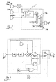
- FIG 1 in which a usual partial section through a stepped Ring combustion chamber of an aircraft gas turbine engine shown is with the reference number 1 the combustion chamber and with the reference number 2 denotes the exit from this combustion chamber 1.
- the combustion chamber 1 reaches according to the illustrated Arrows a pumped by an upstream compressor and compressed gas flow or air flow into it, which carries the required oxygen to the over the (or the multiple rings) Pilot burner 3 and possibly over the (or the multiple existing ring-shaped) main burner 4 in the combustion chamber 1 introduced fuel (this is punctured shown) to burn in the combustion chamber 1.
- the combustion exhaust gases then pass through the combustion chamber outlet 2 According to the arrow, first into the turbine of the engine.
- the combustion chamber 1 is spatially divided into a pilot zone 1a, which is located directly downstream of the pilot burner 3, and in one adjoining it in the direction of flow of the gases Main zone 1b, into which the main burners 4 discharge the fuel.
- the latter that is, a fuel supply to the main zone 1b the combustion chamber 1 via the main burner 4, however, only happens in those operating points of the engine in which a higher Performance development or performance submission required becomes.
- 3 fuel is constantly passed through the pilot burner into the combustion chamber 1.
- FIG. 2 shows a fuel injection system according to the invention, with which the pilot burner 3 and the main burner 4 with Fuel are supplied, schematically and greatly simplified shown.
- the arrow WF shows the total fuel mass flow, dosed via a control valve unit 6 and thus to a certain operating point of the engine adapted is introduced into the combustion chamber 1.
- Such a thing called step valve unit 7 sets which on. part of this total fuel mass flow WF according to arrow 3 ' the pilot burners 3 and which ones (which are complementarily related) Share of this total fuel mass flow WF according to Arrow 4 'is fed to the main burners 4.
- control block 8 is the (electronic) engine controller referred to, which usually contains several rule blocks.
- a first control block 8a is now shown, which is the control valve unit 6 operated or positioned appropriately or sets, and the appropriate (usual) engine control laws contains or takes into account.
- a second control block 8b-shown the staging valve unit 7 controls and therefore rules for the tiered Combustion contains or takes into account.
- This Control block 8b thus determines the so-called split value S, the distribution of the total fuel mass flow WF identifies the pilot burner 3 and the main burner 4 and adjusts the step valve unit 7 accordingly.
- the temporal change in the speed of the high-pressure shaft of the engine that is to say the quotient (dNH / dt) Ref , can also be taken into account, as will be explained below in connection with claim 3.
- FIG. 4 shows a preferred way of limiting the fuel distribution on the pilot burner 3 and on the main burner 4 shown.
- a (temporal) differentiator for the nominal split value S *, reference numerals 10 and the limiter mentioned in the above description section for claim 5 the reference number 11.
- the limit value for this query if necessary, is taken as the input variable with the reference number Denoted 12 and can be, for example, 50%.
- the commanded split value runs through the range between 100% and 40%. Only from a pilot fuel content below The fuel distribution is limited to 50% Pilot burner. This means that the share 4 'in the total fuel mass flow WF, which over the main burner 4 in the Combustion chamber 1 can reach between 0% and 50% can lie.
- FIG. 5 shows a diagram for the preferred range the operating mode of the combustion chamber 1, that is, whether this is operated in pilot operation or in staged operation.
- the output of this scheme is a digital yes / no variable, which indicates whether the main burners 4 are supplied with fuel or not.
- the one switch from the unrated pilot operation to the tiered operation mode below the idle mode the engine preventing function is also with "Idle” denotes, and the function that has an absolute value for gas pressure (P30) and / or gas temperature (T30) considered at the combustion chamber inlet to ensure a stable Ensuring operation of the combustion chamber is also included Denoted "Stability”.
- a fuel injection system results for a stepped combustion chamber in particular of an aircraft gas turbine engine, with which an essentially optimal operation of this combustion chamber 1 is made possible.
- Possible is in particular a map-based, optimized for pollutants Regulation of staged combustion in quasi-stationary Business.
- the control block 8b of the engine controller 8 implementable and previously described rules for the staged combustion allow operation of one or the tiered combustion chamber 1 in the tiered Pilot operation and in tiered mode without significant influence on the safety, stability and thrust of the entire engine during a staging process, including a switching process between the two operating modes is understood.
- the continuously adjustable staging valve unit 7 ensures that both the emission level of the combustion chamber, in particular with respect to NO x, and the temperature profile at the turbine inlet downstream of the combustion chamber 1 are optimized over the entire operating range of the engine.
- the selected method of setting the fuel split that is to say the split value S, between the pilot burners 3 and the main burners 4 thus enables flexible distribution of the fuel in accordance with the current requirements for the control system in the respective operating state.
- this method also allows the combustion chamber's operating behavior to be optimized with regard to combustion stability, burnout behavior and the temperature exit profile over the entire load range of the engine.
- the invention relates to a fuel injection system for a tiered combustion chamber 1 of an aircraft gas turbine engine, the Pilot burner 3 always supplied with a certain amount of fuel will / will, during their main burner (s) 4 only at higher Engine power is metered to fuel, where downstream of a control valve unit which determines the total amount of fuel 6 a this total fuel mass flow (WF) changeable on the pilot burner 3 and on the main burner 4 dividing stage valve unit 7 is provided, both be controlled by an engine controller 8, which for the Control of the staging valve unit 7 the desired engine power based, characterized in that the Engine performance due to the load on the gas turbine combustion chamber 1 in the form of a so-called grading parameter (SP) is characterized, on the basis of which the step valve unit 7 is controlled according to a switching line that the Grading parameters (SP) derived from a functional relationship is that a downstream summation point for Calculation of the difference between a current value of the grading point and a value of the nominal grading point and that the summation point is
Landscapes
- Engineering & Computer Science (AREA)
- Chemical & Material Sciences (AREA)
- Combustion & Propulsion (AREA)
- Mechanical Engineering (AREA)
- General Engineering & Computer Science (AREA)
- Feeding And Controlling Fuel (AREA)
- Output Control And Ontrol Of Special Type Engine (AREA)
Description
- Fig. 1
- eine schematische Darstellung einer gestuften Brennkammer eines Fluggasturbinen-Triebwerks,
- Fig. 2
- eine schematische Teilansicht eines erfindungsgemäßen Triebwerkreglers,
- Fig. 3
- ein Teil-Prinzipschaltbild des erfindungsgemäßen Triebwerkreglers,
- Fig. 4
- ein weiteres Teil-Prinzipschaltbild des erfindungsgemäßen Triebwerkreglers, und
- Fig. 5
- ein Prinzipschaltbild zur Umsetzung in einer digitalen elektronischen Steuereinheit bei einem bevorzugten Ausführungsbeispiel des erfindungsgemäßen Brennstoffeinspritzsystems.
- WF =
- Gesamt-Brennstoffmassenstrom,
- P30 =
- Gasdruck am Brennkammer-Eintritt,
- T30 =
- Gastemperatur am Brennkammer-Eintritt, oder
- T44 =
- Total-Temperatur stromab der Triebwerks-Hochdruckturbine
- T20 =
- Gastemperatur am Triebwerks-Eintritt
Claims (15)
- Brennstoffeinspritzsystem für eine gestufte Brennkammer (1) eines Fluggasturbinen-Triebwerks, deren Pilotbrenner (3) stets mit einer gewissen Brennstoffmenge versorgt wird/werden, während deren Hauptbrenner(n) (4) nur bei höherer Triebwerksleistung Brennstoff zugemessen wird, wobei stromab einer die gesamte Brennstoffmenge bestimmenden Steuer-Ventileinheit (6) eine diesen Gesamt-Brennstoffmassenstrom (WF) auf die Pilotbrenner (3) sowie auf die Hauptbrenner (4) veränderbar aufteilende Stufungs-Ventileinheit (7) vorgesehen ist, die beide von einem Triebwerksregler (8) angesteuert werden, der für die Ansteuerung der Stufungs-Ventileinheit (7) die gewünschte Triebwerksleistung zugrunde legt, dadurch gekennzeichnet, dass die Triebwerksleistung durch die Belastung der Gasturbinen-Brennkammer (1) in Form eines so genannten Stufungsparameters (SP) charakterisiert ist, anhand dessen die Stüfungs-Ventileinheit (7) entsprechend einer Schaltgeraden angesteuert wird, dass der Stufungsparameter (SP) aus einem funktionalen Zusammenhang abgeleitet wird, dass eine nachgeschaltete Summationsstelle zur Berechnung der Differenz zwischen einem aktuellen Wert des Stufungspunktes und einem Wert des nominalen Stufungspunktes vorgesehen ist, und dass der Summationsstelle ein Zeitelement (TIMER) nachgeordnet ist, welches so ausgebildet ist, dass nach dem Über- beziehungsweise Unterschreiten des angepassten Stufungspunktes der Umschaltvorgang zeitlich verzögert wird, wenn die Zeitdauer seit dem Ausführen der letzten Stufung kleiner ist als eine vordefinierte Zeitkonstante, die in einem Kennfeld abgelegt ist.
- Brennstoffeinspritzsystem nach Anspruch 1, dadurch gekennzeichnet, dass das Zeitelement (TIMER) aktivierbar ist, sobald der aktuelle Wert des Stufungspunktes einen Wert 1 annimmt.
- Brennstoffeinspritzsystem nach Anspruch 1 oder 2, dadurch gekennzeichnet, dass das Zeitelement (TIMER) mittels einer Kennfeldsteuerung ansteuerbar ist.
- Brennstoffeinspritzsystem nach Anspruch 3, dadurch gekennzeichnet, dass die Kennfeldsteuerung zur Abgabe eines Steuerungsparameters tMIN,Stufung an das Zeitelement (TIMER) ausgebildet ist.
- Brennstoffeinspritzsystem nach Anspruch 4, dadurch gekennzeichnet, dass der Steuerungsparameter bei schnellem Lastweg klein und bei langsamem Lastweg groß eingestellt ist.
- Brennstoffeinspritzsystem nach einem der Ansprüche 3 bis 5, dadurch gekennzeichnet, dass der Kennfeldsteuerung für das Zeitelement (TIMER) als Eingangsgröße die Ableitung der Hochdruckturbinenwellendrehzahl nach der Zeit (dNH/dt) zuleitbar ist.
- Brennstoffeinspritzsystem nach einem der Ansprüche 1 bis 6, dadurch gekennzeichnet, dass der Ausgangswert SPK* des Zeitelements (TIMER) einem Auswahlelement zuleitbar ist.
- Brennstoffeinspritzsystem nach Anspruch 7, dadurch gekennzeichnet, dass das Auswahlelement so ausgebildet ist, dass bei SPK* = 0 der aktuelle Wert der Stufungspunktberechnung herangezogen wird und dass bei SPK* = 1 der Wert des letzten Zeitschritts (Z-1) verwendet wird
- Brennstoffeinspritzsystem nach einem der Ansprüche 1 bis 8, dadurch gekennzeichnet, dass der Stufungsparameter (SP) aus einem funktionalen Zusammenhang abgeleitet wird:{Gesamt-Brennstoffmassenstrom (WF)} dividiert durch {Gasdruck am Brennkammer-Eintritt (P30)} multipliziert mit {Gastemperatur am Brennkammer-Eintritt (T30)},
das heißt SP = Funktion von [WF / P30 • T30] oder{Gesamt-Brennstoffmassenstrom (WF)} dividiert durch {Gasdruck am Brennkammer-Eintritt (P30)} multipliziert mit {Quadratwurzel der Gastemperatur am Brennkammer-Eintritt (T30)},
das heißt SP = Funktion von [WF / P30 • (T30)½] oder{Gesamt-Brennstoffmassenstrom (WF)} dividiert durch {Gasdruck am Brennkammer-Eintritt (P30)} multipliziert mit {Quadratwurzel des Quotienten aus der Gastemperatur am Brennkammer-Eintritt (T30) und der Gastemperatur am Triebwerks-Eintritt (T20)},
das heißt SP = Funktion von [WF / P30 • (T30 / T20)½] oder{Gesamt-Brennstoffmassenstrom (WF)} dividiert durch {Gasdruck am Brennkammer-Eintritt (P30)} multipliziert mit {Total-Temperatur (T44) stromab der Hochdruckturbine oder der Quadratwurzel hiervon},
das heißt SP = Funktion von [WF / P30 • T44], oder
SP = Funktion von [WF / P30 • (T44)½] - Brennstoffeinspritzsystem nach einem der Ansprüche 1 bis 9, dadurch gekennzeichnet, dass bezüglich des Zuschaltens sowie des Abschaltens der Hauptbrenner (4) vorgesehen ist, dass bei Ansteigen der Triebwerksleistung über den Stufungspunkt die Hauptbrenner zugeschaltet und bei Absinken der Triebwerksleistung unter den Stufungspunkt die Hauptbrenner abgeschaltet werden, und dass zu einem Grundwert des Stufungspunktes, der insbesondere aus einem Kennfeld ermittelt wird, zumindest ein Korrekturglied (ΔSP) in Form eines Offsets addiert wird, durch welches einer der folgenden Einflussparameter berücksichtigt wird:Absolutwert des Gasdruckes (P30) und/oder der Gastemperatur (T30) am Brennkammer-Eintrittkorrigierte Drehzahl des Hochdruckverdichters (N2RT20) und Gasdruck am Triebwerkseintritt (P20)Flughöhe und/oder ausgewählte UmgebungsbedingungenLastwechselgeschwindigkeitVerdichterpumpen
- Brennstoffeinspritzsystem nach einem der Ansprüche 1 bis 10, wobei aus dem Stufungsparameter (SP) über ein Kennfeld ein so genannter Splitwert (S) ermittelt wird, der die Brennstoffaufteilung auf die Pilotbrenner (3) und die Hauptbrenner (4) beschreibt und anhand dessen die Stufungs-Ventileinheit (7) angesteuert wird, dadurch gekennzeichnet, dass in Instationärzuständen des Triebwerkes der Splitwert (S) durch einen Korrekturfaktor angepasst wird, der in Abhängigkeit von der zeitlichen Änderung der Drehzahl insbesondere der Hochdruck-Welle des Triebwerks ermittelt wird.
- Brennstoffeinspritzsystem nach einem der Ansprüche 1 bis 11, dadurch gekennzeichnet, dass auf einen Grenz-Ersatzwert für den Splitwert zurückgegriffen wird, wenn der zeitlich differenzierte berechnete Splitwert einen Grenz-Differenzenwert überschreitet.
- Brennstoffeinspritzsystem nach einem der Ansprüche 1 bis 12, dadurch gekennzeichnet, dass während eines Stufungsvorganges, bei welchem die Hauptbrenner (4) zugeschaltet oder abgeschaltet werden, initiiert durch den Triebwerksregler (8) eine Änderung der Zapfluft-Entnahmerate aus dem Triebwerk verhindert wird.
- Brennstoffeinspritzsystem nach einem der Ansprüche 1 bis 13, gekennzeichnet durch eine Stufungs-Vorwegnahme-Logik, die bei sich abzeichnender Zuschaltung der Hauptbrenner (4) ein kurzzeitiges Befüllen der Hauptbrenner verursacht.
- Brennstoffeinspritzsystem nach einem der Ansprüche 1 bis 14, dadurch gekennzeichnet, dass während eines Anlassvorganges des Triebwerks die Kraftstoffleitungen zu den Hauptbrennern gleichzeitig mit den Leitungen zu den Pilotbrennern befüllt werden, ohne den Füllzustand in den Hauptbrenner-Leitungen zu messen.
Applications Claiming Priority (4)
| Application Number | Priority Date | Filing Date | Title |
|---|---|---|---|
| DE19939812 | 1999-08-21 | ||
| DE19939812A DE19939812A1 (de) | 1999-08-21 | 1999-08-21 | Brennstoffeinspritzsystem für eine gestufte Brennkammer eines Fluggasturbinen-Triebwerks |
| DE10032471 | 2000-07-04 | ||
| DE10032471A DE10032471A1 (de) | 2000-07-04 | 2000-07-04 | Verfahren zur Adaption des Betriebszustandes einer gestuften Brennkammer für Gasturbinen |
Publications (2)
| Publication Number | Publication Date |
|---|---|
| EP1079179A1 EP1079179A1 (de) | 2001-02-28 |
| EP1079179B1 true EP1079179B1 (de) | 2004-11-24 |
Family
ID=26006282
Family Applications (1)
| Application Number | Title | Priority Date | Filing Date |
|---|---|---|---|
| EP00117741A Expired - Lifetime EP1079179B1 (de) | 1999-08-21 | 2000-08-17 | Verfahren zur Adaption des Betriebszustandes einer gestuften Brennkammer für Gasturbinen |
Country Status (3)
| Country | Link |
|---|---|
| US (1) | US7003939B1 (de) |
| EP (1) | EP1079179B1 (de) |
| DE (1) | DE50008726D1 (de) |
Cited By (1)
| Publication number | Priority date | Publication date | Assignee | Title |
|---|---|---|---|---|
| EP3023698A1 (de) | 2014-11-19 | 2016-05-25 | Rolls-Royce Deutschland Ltd & Co KG | Vorrichtung zur bestimmung eines stufungsverhältnisses, eine gasturbine oder ein flugzeugtriebwerk mit einer solchen vorrichtung und eine verwendung dafür |
Families Citing this family (21)
| Publication number | Priority date | Publication date | Assignee | Title |
|---|---|---|---|---|
| US7826954B2 (en) * | 2004-06-25 | 2010-11-02 | Honda Motor Co., Ltd. | System for monitoring sensor outputs of a gas turbine engine |
| US8224552B2 (en) * | 2008-07-10 | 2012-07-17 | General Electric Company | Methods and systems to facilitate over-speed protection |
| US8321119B2 (en) * | 2008-07-10 | 2012-11-27 | General Electric Company | Methods and systems to facilitate over-speed protection |
| US20100005657A1 (en) * | 2008-07-10 | 2010-01-14 | Van Vactor David R | Methods and systems to facilitate over-speed protection |
| DE102008038949A1 (de) * | 2008-08-13 | 2010-02-18 | Ebm-Papst Landshut Gmbh | Sicherungssystem in und Verfahren zum Betrieb einer Verbrennungsanlage |
| EP2348256A1 (de) * | 2010-01-26 | 2011-07-27 | Alstom Technology Ltd | Verfahren zum Betreiben einer Gasturbine und Gasturbine |
| JP5635948B2 (ja) * | 2010-07-23 | 2014-12-03 | 三菱日立パワーシステムズ株式会社 | 燃焼器の制御方法及び制御装置 |
| FR2971815B1 (fr) * | 2011-02-21 | 2015-07-24 | Turbomeca | Dispositif et procede d'injection privilegiee |
| CH705179A1 (de) * | 2011-06-20 | 2012-12-31 | Alstom Technology Ltd | Verfahren zum Betrieb einer Verbrennungsvorrichtung sowie Verbrennungsvorrichtung zur Durchführung des Verfahrens. |
| US9328633B2 (en) * | 2012-06-04 | 2016-05-03 | General Electric Company | Control of steam temperature in combined cycle power plant |
| US9541005B2 (en) * | 2012-09-28 | 2017-01-10 | Pratt & Whitney Canada Corp. | Adaptive fuel manifold filling function for improved engine start |
| FR3010140B1 (fr) * | 2013-09-03 | 2015-10-02 | Snecma | Systeme et procede d'injection de carburant dans une chambre de combustion d'un moteur |
| EP3056814A1 (de) * | 2015-02-13 | 2016-08-17 | General Electric Technology GmbH | Verfahren zur steuerung der kraftstoffverteilung zwischen verschiedenen stufen einer gasturbinenbrennkammer |
| US11022041B2 (en) | 2015-10-13 | 2021-06-01 | Raytheon Technologies Corporation | Sensor snubber block for a gas turbine engine |
| US11713723B2 (en) | 2019-05-15 | 2023-08-01 | Pratt & Whitney Canada Corp. | Method and system for operating an engine |
| US11156164B2 (en) | 2019-05-21 | 2021-10-26 | General Electric Company | System and method for high frequency accoustic dampers with caps |
| US11174792B2 (en) | 2019-05-21 | 2021-11-16 | General Electric Company | System and method for high frequency acoustic dampers with baffles |
| CN110516337B (zh) * | 2019-08-20 | 2023-05-19 | 成立航空股份有限公司 | 航空发动机燃烧室部件重量指标的确定方法 |
| US11760500B2 (en) | 2019-11-11 | 2023-09-19 | Pratt & Whitney Canada Corp. | Systems and methods for filling a fuel manifold of a gas turbine engine |
| GB2601499A (en) * | 2020-12-01 | 2022-06-08 | Siemens Energy Global Gmbh & Co Kg | Method of Controlling a Combustor |
| US12366360B1 (en) | 2024-04-29 | 2025-07-22 | Pratt & Whitney Canada Corp. | Gas turbine adaptive secondary fuel filling profile |
Family Cites Families (14)
| Publication number | Priority date | Publication date | Assignee | Title |
|---|---|---|---|---|
| US4735052A (en) * | 1985-09-30 | 1988-04-05 | Kabushiki Kaisha Toshiba | Gas turbine apparatus |
| US4920740A (en) * | 1987-11-23 | 1990-05-01 | Sundstrand Corporation | Starting of turbine engines |
| CA2072275A1 (en) | 1991-08-12 | 1993-02-13 | Phillip D. Napoli | Fuel delivery system for dual annular combustor |
| US5261222A (en) * | 1991-08-12 | 1993-11-16 | General Electric Company | Fuel delivery method for dual annular combuster |
| DE4223828A1 (de) | 1992-05-27 | 1993-12-02 | Asea Brown Boveri | Verfahren zum Betrieb einer Brennkammer einer Gasturbine |
| US5406798A (en) * | 1993-10-22 | 1995-04-18 | United Technologies Corporation | Pilot fuel cooled flow divider valve for a staged combustor |
| US5402634A (en) | 1993-10-22 | 1995-04-04 | United Technologies Corporation | Fuel supply system for a staged combustor |
| US5465570A (en) | 1993-12-22 | 1995-11-14 | United Technologies Corporation | Fuel control system for a staged combustor |
| FR2727192B1 (fr) | 1994-11-23 | 1996-12-20 | Snecma | Systeme d'injection d'une chambre de combustion a deux tetes |
| JP3502171B2 (ja) * | 1994-12-05 | 2004-03-02 | 株式会社日立製作所 | ガスタービンの制御方法 |
| DE19518634C2 (de) | 1995-05-20 | 1998-10-01 | Pierburg Luftfahrtgeraete | Gerät zur Kraftstoffzumessung und -verteilung |
| US5735117A (en) * | 1995-08-18 | 1998-04-07 | Fuel Systems Textron, Inc. | Staged fuel injection system with shuttle valve and fuel injector therefor |
| GB9525370D0 (en) * | 1995-12-12 | 1996-02-14 | Lucas Ind Plc | Flow sensor and fuel control system |
| DE19728375A1 (de) | 1997-07-03 | 1999-01-07 | Bmw Rolls Royce Gmbh | Betriebsverfahren für eine axial gestufte Brennkammer einer Fluggasturbine |
-
2000
- 2000-08-17 DE DE50008726T patent/DE50008726D1/de not_active Expired - Lifetime
- 2000-08-17 EP EP00117741A patent/EP1079179B1/de not_active Expired - Lifetime
- 2000-08-21 US US09/642,096 patent/US7003939B1/en not_active Expired - Fee Related
Cited By (2)
| Publication number | Priority date | Publication date | Assignee | Title |
|---|---|---|---|---|
| EP3023698A1 (de) | 2014-11-19 | 2016-05-25 | Rolls-Royce Deutschland Ltd & Co KG | Vorrichtung zur bestimmung eines stufungsverhältnisses, eine gasturbine oder ein flugzeugtriebwerk mit einer solchen vorrichtung und eine verwendung dafür |
| DE102014223637A1 (de) | 2014-11-19 | 2016-06-09 | Rolls-Royce Deutschland Ltd & Co Kg | Vorrichtung zur Bestimmung eines Stufungsverhältnisses, eine Gasturbine oder ein Flugzeugtriebwerk mit einer solchen Vorrichtung und eine Verwendung dafür |
Also Published As
| Publication number | Publication date |
|---|---|
| US7003939B1 (en) | 2006-02-28 |
| DE50008726D1 (de) | 2004-12-30 |
| EP1079179A1 (de) | 2001-02-28 |
Similar Documents
| Publication | Publication Date | Title |
|---|---|---|
| EP1079179B1 (de) | Verfahren zur Adaption des Betriebszustandes einer gestuften Brennkammer für Gasturbinen | |
| DE3543908C1 (de) | Einrichtung zur Steuerung der Brennstoffzufuhr zum Nachbrenner eines Nebenstrom-Gasturbinenstrahltriebwerkes | |
| EP3023698B1 (de) | Vorrichtung zur bestimmung eines stufungsverhältnisses, eine gasturbine oder ein flugzeugtriebwerk mit einer solchen vorrichtung und eine verwendung dafür | |
| DE69010080T2 (de) | Brennstoffregelsystem eines Gasturbinenmotors mit verbesserter Wiederzündfähigkeit. | |
| DE1912383C2 (de) | Elektronische Regelanordnung zum Hochfahren einer Gasturbinenanlage auf Betriebsdrehzahl | |
| DE102006008483B4 (de) | Verbrennungssteuervorrichtung für eine Gasturbine | |
| DE102006008714B4 (de) | Verbrennungssteuervorrichtung für eine Gasturbine | |
| DE68906898T2 (de) | Kraftstoffsteuerungssystem. | |
| DE69614059T2 (de) | Kraftstoffregelsystem für eine Gasturbine | |
| DE2140115A1 (de) | Elektrisches Steuersystem für Gas turbinentnebwerke | |
| CH708571A2 (de) | Gasturbinensystem und Verfahren zur Steuerung der Brennstoffverteilung in den Brennkammern einer Gasturbine. | |
| AT516134B1 (de) | Brennkraftmaschine mit einer Regeleinrichtung | |
| DE102011054175A1 (de) | Verfahren, Vorrichtung und System zur Zündung eines breiten Spektrums an Turbinenbrennstoffen | |
| DE102004036911A1 (de) | Betriebsverfahren für eine Feuerungsanlage | |
| CH701827A2 (de) | Brennkammer mit Verbrennungsdynamiksteuerung mehrerer Brennstoffdüsen. | |
| DE112015003887B4 (de) | Steuervorrichtung, System und Steuerverfahren | |
| DE69217093T2 (de) | Verbrennungsvorrichtung und Steuerverfahren | |
| DE1601560A1 (de) | Steuersystem fuer Axialstroemungskompressoren,insbesondere fuer Gasturbinentriebwerke | |
| DE112015003604T5 (de) | Strömungsverhältniszahl-berechnungsvorrichtung, mit selbiger vorgesehene steuervorrichtung, mit besagter steuervorrichtung vorgesehene gasturbinenanlage, strömungsverhältniszahl-berechnungsverfahren, und verfahren zum steuern des brennstoffsystems | |
| EP0974789B1 (de) | Verfahren zum Betrieb einer Gasturbinenbrennkammer mit flüssigem Brennstoff | |
| WO2009103097A1 (de) | Brennkraftmaschine | |
| EP1533569B1 (de) | Verfahren zum Betrieb einer Feuerungseinrichtung | |
| DE10032471A1 (de) | Verfahren zur Adaption des Betriebszustandes einer gestuften Brennkammer für Gasturbinen | |
| DE2539007C2 (de) | Brennstoffregelsystem für eine Hilfsbrennkammer einer mit Abgasturboladung arbeitenden, kompressionsgezündeten Einspritzbrennkraftmaschine | |
| DE2906223A1 (de) | Brennstoffsteuerung fuer turbinen-nachbrenner |
Legal Events
| Date | Code | Title | Description |
|---|---|---|---|
| PUAI | Public reference made under article 153(3) epc to a published international application that has entered the european phase |
Free format text: ORIGINAL CODE: 0009012 |
|
| AK | Designated contracting states |
Kind code of ref document: A1 Designated state(s): DE FR GB |
|
| AX | Request for extension of the european patent |
Free format text: AL;LT;LV;MK;RO;SI |
|
| RIN1 | Information on inventor provided before grant (corrected) |
Inventor name: RACKWITZ, LEIF, DIPL-ING. Inventor name: SCHMIDT, KLAUS-JUERGEN, DR. ING. |
|
| RAP1 | Party data changed (applicant data changed or rights of an application transferred) |
Owner name: ROLLS-ROYCE DEUTSCHLAND LTD & CO KG |
|
| 17P | Request for examination filed |
Effective date: 20010806 |
|
| AKX | Designation fees paid |
Free format text: DE FR GB |
|
| GRAP | Despatch of communication of intention to grant a patent |
Free format text: ORIGINAL CODE: EPIDOSNIGR1 |
|
| GRAS | Grant fee paid |
Free format text: ORIGINAL CODE: EPIDOSNIGR3 |
|
| GRAA | (expected) grant |
Free format text: ORIGINAL CODE: 0009210 |
|
| AK | Designated contracting states |
Kind code of ref document: B1 Designated state(s): DE FR GB |
|
| REG | Reference to a national code |
Ref country code: GB Ref legal event code: FG4D Free format text: NOT ENGLISH |
|
| REF | Corresponds to: |
Ref document number: 50008726 Country of ref document: DE Date of ref document: 20041230 Kind code of ref document: P |
|
| GBT | Gb: translation of ep patent filed (gb section 77(6)(a)/1977) |
Effective date: 20041216 |
|
| PLBE | No opposition filed within time limit |
Free format text: ORIGINAL CODE: 0009261 |
|
| STAA | Information on the status of an ep patent application or granted ep patent |
Free format text: STATUS: NO OPPOSITION FILED WITHIN TIME LIMIT |
|
| ET | Fr: translation filed | ||
| 26N | No opposition filed |
Effective date: 20050825 |
|
| REG | Reference to a national code |
Ref country code: DE Ref legal event code: R082 Ref document number: 50008726 Country of ref document: DE Representative=s name: HOEFER & PARTNER, DE |
|
| REG | Reference to a national code |
Ref country code: DE Ref legal event code: R082 Ref document number: 50008726 Country of ref document: DE Representative=s name: HOEFER & PARTNER, DE Effective date: 20130402 Ref country code: DE Ref legal event code: R081 Ref document number: 50008726 Country of ref document: DE Owner name: ROLLS-ROYCE DEUTSCHLAND LTD & CO KG, DE Free format text: FORMER OWNER: ROLLS-ROYCE DEUTSCHLAND LTD & CO KG, 15827 BLANKENFELDE, DE Effective date: 20130402 Ref country code: DE Ref legal event code: R082 Ref document number: 50008726 Country of ref document: DE Representative=s name: HOEFER & PARTNER PATENTANWAELTE MBB, DE Effective date: 20130402 |
|
| REG | Reference to a national code |
Ref country code: FR Ref legal event code: PLFP Year of fee payment: 17 |
|
| PGFP | Annual fee paid to national office [announced via postgrant information from national office to epo] |
Ref country code: GB Payment date: 20160830 Year of fee payment: 17 Ref country code: DE Payment date: 20160826 Year of fee payment: 17 |
|
| PGFP | Annual fee paid to national office [announced via postgrant information from national office to epo] |
Ref country code: FR Payment date: 20160825 Year of fee payment: 17 |
|
| REG | Reference to a national code |
Ref country code: DE Ref legal event code: R119 Ref document number: 50008726 Country of ref document: DE |
|
| GBPC | Gb: european patent ceased through non-payment of renewal fee |
Effective date: 20170817 |
|
| REG | Reference to a national code |
Ref country code: FR Ref legal event code: ST Effective date: 20180430 |
|
| PG25 | Lapsed in a contracting state [announced via postgrant information from national office to epo] |
Ref country code: GB Free format text: LAPSE BECAUSE OF NON-PAYMENT OF DUE FEES Effective date: 20170817 Ref country code: DE Free format text: LAPSE BECAUSE OF NON-PAYMENT OF DUE FEES Effective date: 20180301 |
|
| PG25 | Lapsed in a contracting state [announced via postgrant information from national office to epo] |
Ref country code: FR Free format text: LAPSE BECAUSE OF NON-PAYMENT OF DUE FEES Effective date: 20170831 |