EP1079026B1 - Vortriebsrohr für die Herstellung einer im wesentlichen horizontal verlaufenden Rohrleitung - Google Patents
Vortriebsrohr für die Herstellung einer im wesentlichen horizontal verlaufenden Rohrleitung Download PDFInfo
- Publication number
- EP1079026B1 EP1079026B1 EP00117988A EP00117988A EP1079026B1 EP 1079026 B1 EP1079026 B1 EP 1079026B1 EP 00117988 A EP00117988 A EP 00117988A EP 00117988 A EP00117988 A EP 00117988A EP 1079026 B1 EP1079026 B1 EP 1079026B1
- Authority
- EP
- European Patent Office
- Prior art keywords
- pipe
- drive
- holes
- wall
- filter
- Prior art date
- Legal status (The legal status is an assumption and is not a legal conclusion. Google has not performed a legal analysis and makes no representation as to the accuracy of the status listed.)
- Expired - Lifetime
Links
- 238000010276 construction Methods 0.000 title claims description 3
- 239000000463 material Substances 0.000 claims abstract description 21
- 239000007788 liquid Substances 0.000 claims abstract description 10
- 238000000034 method Methods 0.000 claims abstract description 5
- 229920000642 polymer Polymers 0.000 claims abstract description 3
- 239000002986 polymer concrete Substances 0.000 claims description 15
- XLYOFNOQVPJJNP-UHFFFAOYSA-N water Substances O XLYOFNOQVPJJNP-UHFFFAOYSA-N 0.000 claims 3
- 239000007767 bonding agent Substances 0.000 claims 2
- 238000007599 discharging Methods 0.000 claims 2
- 239000002245 particle Substances 0.000 claims 1
- 238000004519 manufacturing process Methods 0.000 abstract description 6
- 239000011230 binding agent Substances 0.000 abstract description 4
- 239000004567 concrete Substances 0.000 abstract description 2
- 239000008187 granular material Substances 0.000 abstract 1
- 239000000853 adhesive Substances 0.000 description 2
- 230000001070 adhesive effect Effects 0.000 description 2
- 229920003023 plastic Polymers 0.000 description 2
- 229920005989 resin Polymers 0.000 description 2
- 239000011347 resin Substances 0.000 description 2
- 230000005540 biological transmission Effects 0.000 description 1
- 238000005260 corrosion Methods 0.000 description 1
- 230000007797 corrosion Effects 0.000 description 1
- 230000001419 dependent effect Effects 0.000 description 1
- 238000005553 drilling Methods 0.000 description 1
- 238000005516 engineering process Methods 0.000 description 1
- 239000003365 glass fiber Substances 0.000 description 1
- 238000009434 installation Methods 0.000 description 1
- 230000035699 permeability Effects 0.000 description 1
- 229920000728 polyester Polymers 0.000 description 1
- 239000011148 porous material Substances 0.000 description 1
- 238000002360 preparation method Methods 0.000 description 1
- 230000001141 propulsive effect Effects 0.000 description 1
- 239000011150 reinforced concrete Substances 0.000 description 1
- 230000003014 reinforcing effect Effects 0.000 description 1
- 239000002689 soil Substances 0.000 description 1
- 238000005728 strengthening Methods 0.000 description 1
- 229920001567 vinyl ester resin Polymers 0.000 description 1
- 230000003313 weakening effect Effects 0.000 description 1
Images

Classifications
-
- E—FIXED CONSTRUCTIONS
- E02—HYDRAULIC ENGINEERING; FOUNDATIONS; SOIL SHIFTING
- E02B—HYDRAULIC ENGINEERING
- E02B11/00—Drainage of soil, e.g. for agricultural purposes
- E02B11/005—Drainage conduits
-
- Y—GENERAL TAGGING OF NEW TECHNOLOGICAL DEVELOPMENTS; GENERAL TAGGING OF CROSS-SECTIONAL TECHNOLOGIES SPANNING OVER SEVERAL SECTIONS OF THE IPC; TECHNICAL SUBJECTS COVERED BY FORMER USPC CROSS-REFERENCE ART COLLECTIONS [XRACs] AND DIGESTS
- Y10—TECHNICAL SUBJECTS COVERED BY FORMER USPC
- Y10S—TECHNICAL SUBJECTS COVERED BY FORMER USPC CROSS-REFERENCE ART COLLECTIONS [XRACs] AND DIGESTS
- Y10S138/00—Pipes and tubular conduits
- Y10S138/07—Resins
Definitions
- the invention relates to a jacking pipe for the production of a substantially horizontally extending pipe whose wall consists of polymer concrete.
- Such jacking pipes are used for example for the production of sewers, with a significant advantage is that the lines can be laid without the need to dug a trench.
- the propulsion technique uses the pipeline as a means of transmitting the forces required for propulsion. This allows a significantly more cost-effective production of the line, although the design of the jacking pipes must take into account the propulsive forces to be transmitted. Due to the use of polymer concrete pipes, the finished pipe in operation also satisfies all practical requirements in terms of resistance to aggressive liquids and thus the service life.
- the post-published EP 1 002 906 A1 describes a well pipe with the same longitudinally within its wall extending and spaced over the circumference of the tube spaced rods, wherein the well pipe may consist of polymer concrete and designed as glass fiber rods rods transmit the axial tensile loads.
- the DE 72 06 442 describes a self-supporting tube well filter with a granular filter casing, which is assembled without the use of support elements only by plastic adhesive and plastic contact strengthening.
- the DE 36 16 445 C1 describes a corrosion resistant pipe made of polymer concrete, wherein embedded in the tubular body in the longitudinal and annular direction continuous reinforcing elements such as rods, wires or bands are embedded.
- the tube should have the smallest possible wall thickness and at the same time be biased to produce a compressive bias.
- the invention has for its object to design a propulsion tube of the type described in the introduction so that it can also be used as a filter tube or drainage tube, z. B. for receiving leachate, is usable.
- the wall of the jacking pipe is provided with at least one opening, which is filled in each case with a liquid-permeable filter material, which filter material is formed by binder-bound gravel-like grains.
- a Polymer concrete thus consist of a liquid-permeable filter material which is formed by bound with binder, in particular with polymer, gravel-like grains.
- the wall of the polymer concrete pipe may be provided with a plurality of openings, which are each filled with the liquid-permeable filter material.
- These openings may be holes, but also, for example, strip-shaped, extending in the longitudinal direction of the tube openings, which are each filled with appropriately strip-shaped trained filter material.
- the jacking pipe may consist predominantly or completely of polymer concrete.
- the polymer concrete portion of the pipe may be a continuous structure that substantially determines the shape of the pipe.
- the structure may be for this purpose e.g. be net or substantially barrel-shaped, without being limited thereto.
- the area of the pipe made of polymer concrete can form the force-absorbing structure of the pipe.
- propulsion tube 10 is provided with round holes 12, which are each closed by a plug 14 made of filter gravel.
- This plug 14 can as
- Kiesklebefilter be formed and consist of filter kies and, for example, polyester or vinyl ester resin. These resins can also be used as binders for the polymer concrete. This also applies to the following embodiments.
- the filter plugs 14 have a pore volume which has the desired permeability to the liquid to be taken up by the tube 10.
- the compressive strength of the plugs 14 is significantly less than that of the polymer concrete of the surrounding wall.
- this is not disadvantageous because the wall 16 as a whole is dimensioned so that it is able to absorb the load which is effective at maximum propelling force.
- the jacking pipe according to the Fig. 1 and 2 with an inner diameter of 400 mm and an outer diameter of 550 mm, ie a wall thickness of 75 mm be provided with holes whose largest diameter is 2.54 cm.
- holes are arranged along the longitudinal extent of the tube at intervals of, for example, 10.0 cm, wherein the individual rows in the circumferential direction also a distance of 10.0 cm.
- the arrangement is made such that the holes of two adjacent rows of holes are offset from each other, as this Fig. 1 shows.
- the front ends 18 of the jacking pipe 16 are formed in the usual way for jacking pipes. This also applies to the connecting elements for connecting two adjacent tubes and seals located between the two tubes, etc.
- the embodiments and elements can be provided or used, which are common and known for connecting jacking pipes for producing a pipe string. This also applies to the other embodiments, which are described below.
- Fig. 3 is essentially consistent with that of Fig. 1 and 2 match, so that the same or corresponding parts are also provided with the same reference numerals, in Fig. 3 are each 100 higher.
- the openings 112 of the tube 110 of the Fig. 3 are formed as extending in the longitudinal direction of the tube 110 strips which are closed by correspondingly shaped strip-shaped body 114 made of filter material.
- the drawing shows that the openings 112 are narrower inwardly from the outer surface, so that consequently the filter body 114 have approximately the shape of a blunt wedge.
- the apertures in the tube wall closing filter body can be preformed and z. B. be attached using an adhesive to the pipe wall.
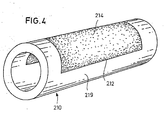
- Fig. 4 are parts that comply with those of the embodiment according to Fig. 1 match or correspond to the same, but provided by 200 higher reference numerals.
- the arrangement is such that the recess 212 occupies a contiguous larger surface, which extends for example over two-thirds of the length of the tube 210 and over about 180 ° of the circumference of the tube 210. Accordingly, this also forms the recess 212 filling Filter material a contiguous body 214, which forms a substantial part of the shell of the tube 210.
- An advantage of this embodiment may be that when installing the tube 210 in the in Fig.
- the lower portion of the inner tube cross-section forms a channel for the outflowing liquid, which is not interrupted by filter areas through which, if necessary, liquid could escape from the tube 210.
- the teaching according to the invention is applicable in many ways, since it has been found that the use of perforated pipes as jacking pipes, the holes are filled through plugs of filter material, and / or of pipes with differently shaped, possibly also large openings are provided, which are filled with filter material, in any case is possible if the dimensioning of the tubes and / or the arrangement of the apertures take into account the need for the transmission of the feed forces.
- the jacking pipes according to the invention are suitable for example for the production of seepage pipes in landfills, but also for the production of essentially horizontally arranged filter wells.
Landscapes
- Engineering & Computer Science (AREA)
- General Engineering & Computer Science (AREA)
- Life Sciences & Earth Sciences (AREA)
- Agronomy & Crop Science (AREA)
- Mechanical Engineering (AREA)
- Civil Engineering (AREA)
- Structural Engineering (AREA)
- Rigid Pipes And Flexible Pipes (AREA)
- Bending Of Plates, Rods, And Pipes (AREA)
- Sewage (AREA)
- Investigation Of Foundation Soil And Reinforcement Of Foundation Soil By Compacting Or Drainage (AREA)
Description
- Die Erfindung betrifft ein Vortriebsrohr für die Herstellung einer im wesentlichen horizontal verlaufenden Rohrleitung, dessen Wandung aus Polymerbeton besteht. Derartige Vortriebsrohre werden beispielsweise für die Herstellung von Abwasserkanälen verwendet, wobei ein wesentlicher Vorteil darin besteht, daß die Leitungen verlegt werden können, ohne daß dazu ein Graben ausgehoben zu werden braucht.
- Es ist bekannt, horizontal verlaufende Versorgungs- und Entsorgungsleitungen sowie Filterbrunnen unter Anwendung der Horizontal-Bohrtechnik grabenlos einzubauen. Diese Technik ist jedoch relativ aufwendig, da zusätzlich ein Bohrgerät verwendet werden muß und somit die Bohrvortrieb einerseits und das Einbauen der Leitung andererseits technisch und arbeitsmäßig aufeinander abgestimmt werden müssen.
- Demgegenüber verwendet die Vortriebstechnik die Rohrleitung als Mittel zur Übertragung der Kräfte, die für den Vortrieb erforderlich sind. Dies ermöglicht eine merklich kostengünstigere Herstellung der Leitung, obwohl die Ausgestaltung der Vortriebsrohre den zu übertragenden Vortriebskräften Rechnung tragen muß. Aufgrund der Verwendung von Polymerbeton-Rohren genügt die fertige Leitung im Betrieb auch bezüglich der Beständigkeit im Hinblick auf aggressive Flüssigkeiten und somit der Standdauer allen praktischen Anforderungen.
- Bislang sind Vortriebsrohre aus Polymerbeton ausschließlich mit einer geschlossenen Wandung zur Herstellung von Versorgungs- und Entsorgungsleitungen verwendet worden, bei denen das Einsickern von Flüssigkeit aus dem umgebenden Erdreich oder anderen die Rohrleitung umgebenden Materialien durch die Rohrwandung weder möglich noch vorgesehen ist (TIS, 10/94, "Abwasserkanäle und -leitungen aus Polymerbeton"; Beton- und Stahlbetonbau 5/1969, 113-116).
- Die nachveröffentlichte
EP 1 002 906 A1 beschreibt ein Brunnenrohr mit in Längsrichtung desselben innerhalb seiner Wandung verlaufenden und über den Umfang des Rohres in Abständen voneinander angeordneten Stäben, wobei das Brunnenrohr aus Polymerbeton bestehen kann und die als Glasfaserstäbe ausgebildeten Stäbe die axialen Zugbelastungen übertragen. - Die
DE 72 06 442 beschreibt einen selbsttragenden Rohrbrunnenfilter mit einem körnigen Filtermantel, der ohne Verwendung von Stützelementen lediglich durch Kunststoffkleber und plastische Kontaktverfestigung zusammengefügt ist. - Die
DE 36 16 445 C1 beschreibt ein korrosionsbeständiges Rohr aus Polymerbeton, wobei in den Rohrkörper in Längs- und Ringrichtung verlaufende durchgehende Bewehrungselemente wie Stäbe, Drähte oder Bänder eingebettet sind. Hierdurch soll das Rohr eine möglichst geringe Wanddicke aufweisen und zugleich unter Erzeugung einer Druckvorspannung vorgespannt werden. - Demzufolge liegt der Erfindung die Aufgabe zugrunde, ein Vortriebsrohr der einleitend beschriebenen Art so auszugestalten, daß es auch als Filterrohr oder Drainagerohr, z. B. zur Aufnahme von Sickerwässern, verwendbar ist.
- Diese Aufgabe wird dadurch gelöst, dass die Wandung des Vortriebsrohres mit wenigstens einer Durchbrechung versehen ist, die jeweils mit einem für Flüssigkeit durchlässigen Filtermaterial ausgefüllt ist, welches Filtermaterial von mit Bindemittel gebundenen kiesartigen Körnern gebildet wird. Wenigstens Teile der Wandung des Vortriebsrohres a Polymerbeton bestehen somit aus einem für Flüssigkeit durchlässigen Filtermaterial, welches von mit Bindemittel, insbesondere mit Polymer, gebundenen kiesartigen Körnern gebildet wird.
- Es hat sich gezeigt, daß es möglich ist, die Wandung der Rohre trotz der durch die Durchbrechungen eintretenden Schwächung so zu bemessen, daß sie in der Lage sind, die jeweils auftretende maximale Vortriebskraft aufzunehmen und weiterzuleiten.
- Im einzelnen kann die Wandung des Polymerbeton-Rohres mit mehreren Durchbrechungen versehen sein, die jeweils mit dem für Flüssigkeit durchlässige Filtermaterial ausgefüllt sind. Bei diesen Durchbrechungen kann es sich um Löcher, jedoch auch beispielsweise um streifenförmige, in Längsrichtung des Rohres verlaufende Durchbrechungen handeln, die jeweils mit entsprechend leistenförmig ausgebildetem Filtermaterial ausgefüllt sind. Das Vortriebsrohr kann überwiegend oder vollständig aus Polymerbeton bestehen. Der aus Polymerbeton bestehende Bereich des Rohres kann ein zusammenhängendes Gebilde darstellen, das die Gestalt des Rohres im wesentlichen bestimmt. Das Gebilde kann hierzu z.B. netz- oder im wesentlichen tonnenförmigartig ausgebildet sein, ohne hierauf beschränkt zu sein. Der ist aus Polymerbeton bestehende Bereich des Rohres kann die kraftaufnehmende Struktur des Rohres bilden.
- Weitere Einzelheiten der Erfindung ergeben sich aus den Unteransprüchen.
- In der Zeichnung sind einige Ausführungsbeispiele der Erfindung dargestellt. Es zeigen:
- Fig. 1
- die perspektivische Ansicht eines als Filter- oder Sickerrohr ausgebildeten Vortriebsrohres,
- Fig. 2
- einen Schnitt nach der Linie II-II der
Fig. 1 , - Fig. 3
- eine der
Fig. 1 entsprechende Darstellung einer zwei- ten Ausführungsform, - Fig. 4
- eine der
Fig. 1 entsprechende Darstellung einer dritten Ausführungsform. - Das in den
Fig. 1 und 2 dargestellte Vortriebsrohr 10 ist mit runden Löchern 12 versehen, die jeweils durch einen Stopfen 14 aus Filterkies verschlossen sind. Dieser Stopfen 14 kann als - Kiesklebefilter ausgebildet seinn und aus Filterkiesen und beispielsweise Polyester- oder Vinylesterharz bestehen. Diese Harze können auch als Bindemittel für den Polymerbeton verwendet werden. Dies gilt auch für die folgenden Ausführungsbeispiele.
- Die Filterstopfen 14 weisen ein Porenvolumen auf, das die gewünschte Durchlässigkeit für die vom Rohr 10 aufzunehmende Flüssigkeit hat. Die Druckfestigkeit der Stopfen 14 ist merklich geringer als die des Polymerbetons der umgebenden Wandung. Dies ist jedoch nicht nachteilig, da die Wandung 16 insgesamt so bemessen ist, daß sie die Belastung, die bei maximaler Vortriebskraft wirksam wird, aufzunehmen in der Lage ist. So kann das Vortriebsrohr gemäß den
Fig. 1 und 2 bei einem Innendurchmesser von 400 mm und einem Außendurchmesser von 550 mm, also einer Wanddicke von 75 mm mit Löchern versehen sein, deren größter Durchmesser 2,54 cm beträgt. Diese Löcher sind entlang der Längserstreckung des Rohres in Abständen von beispielsweise 10,0 cm angeordnet, wobei die einzelnen Reihen in Umfangsrichtung ebenfalls einen Abstand von 10,0 cm aufweisen. Die Anordnung ist dabei so getroffen, daß die Löcher zweier benachbarter Lochreihen gegeneinander versetzt angeordnet sind, wie diesFig. 1 zeigt. - Die Stirnenden 18 des Vortriebsrohres 16 sind in der für Vortriebsrohre üblichen Weise ausgebildet. Dies gilt auch für die Verbindungselemente zur Verbindung zweier benachbarter Rohre und für zwischen beiden Rohren befindliche Dichtungen usw. Hier können die Ausgestaltungen und Elemente vorgesehen sein bzw. verwendet werden, die allgemein zur Verbindung von Vortriebsrohren zur Herstellung eines Rohrstranges üblich und bekannt sind. Dies gilt auch für die übrigen Ausführungsbeispiele, die im folgenden beschrieben werden.
- Das Ausführungsbeispiel gemäß
Fig. 3 stimmt im wesentlichen mit dem derFig. 1 und 2 überein, so daß gleiche oder einander entsprechende Teile auch mit gleichen Bezugszeichen versehen sind, die inFig. 3 jeweils um 100 höher sind. - Die Durchbrechungen 112 des Rohres 110 der
Fig. 3 sind als in Längsrichtung des Rohres 110 verlaufende Streifen ausgebildet, die durch entsprechend geformte leistenförmige Körper 114 aus Filtermaterial verschlossen sind. Die Zeichnung läßt erkennen, daß die Durchbrechungen 112 von der äußeren Mantelfläche nach innen schmaler werden, so daß demzufolge die Filterkörper 114 etwa die Form eines stumpfen Keiles haben. Die die Durchbrechungen in der Rohrwandung verschließenden Filterkörper können vorgeformt sein und z. B. unter Verwendung eines Klebers an der Rohrwandung befestigt sein. - Bei der Ausführungsform gemäß
Fig. 4 sind Teile, die mit denen der Ausführungsform gemäßFig. 1 übereinstimmen bzw. diesen entsprechen, mit gleichen, jedoch um 200 höheren Bezugszeichen versehen. InFig. 4 ist die Anordnung so getroffen, daß die Ausnehmung 212 eine zusammenhängende größere Fläche einnimmt, die sich beispielsweise über zwei Drittel der Länge des Rohres 210 und über etwa 180° des Umfangs des Rohres 210 erstreckt. Demzufolge bildet auch das diese Ausnehmung 212 ausfüllende Filtermaterial einen zusammenhängenden Körper 214, der einen wesentlichen Teil des Mantels des Rohres 210 bildet. Ein Vorteil dieser Ausgestaltung kann darin bestehen, daß bei Einbau des Rohres 210 in der inFig. 4 dargestellten Weise der untere Bereich des inneren Rohrquerschnittes ein Gerinne für die abfließende Flüssigkeit bildet, welches nicht durch Filterbereiche unterbrochen ist, durch welche ggf. auch Flüssigkeit aus dem Rohr 210 austreten könnte. Welche der jeweiligen Ausgestaltungen in Betracht kommt, wird von den jeweiligen Gegebenheiten abhängen. - Die Lehre gemäß der Erfindung ist in vielfacher Hinsicht anwendbar, da sich herausgestellt hat, daß die Verwendung von perforierten Rohren als Vortriebsrohre, deren Löcher durch Verschlußstopfen aus Filtermaterial ausgefüllt sind, und/oder von Rohren, die mit anders geformten, ggf. auch großflächigen Durchbrechungen versehen sind, die mit Filtermaterial ausgefüllt sind, jedenfalls dann möglich ist, wenn die Dimensionierung der Rohre und/oder die Anordnung der Durchbrechungen der Notwendigkeit der Übertragung der Vorschubkräfte Rechnung tragen.
- Die Vortriebsrohre gemäß der Erfindung sind beispielsweise für die Herstellung von Sickerleitungen in Deponien, aber auch für die Herstellung im wesentlichen horizontal angeordneten Filterbrunnen geeignet.
Claims (14)
- Vortriebsrohr (10, 110, 210) für die Herstellung einer im wesentlichen horizontal verlaufenden Rohrleitung, dessen Wandung (16, 116, 216) aus Polymerbeton besteht, dadurch gekennzeichnet, dass die Wandung des Vortriebsrohres mit wenigstens einer Durchbrechung (12, 112, 212) versehen ist, die jeweils mit einem für Flüssigkeit durchlässigen Filtermaterial (14, 114, 214) ausgefüllt ist, welches Filtermaterial von mit Bindemittel gebundenen kiesartigen Körnern gebildet wird.
- Vortriebsrohr nach Anspruch 1, dadurch gekennzeichnet, dass die Durchbrechungen als im wesentlichen radial verlaufende Löcher (12) ausgebildet sind, die jeweils durch einen Stopfen (14) aus Filtermaterial ausgefüllt sind.
- Vortriebsrohr nach Anspruch 1, dadurch gekennzeichnet, dass die Rohrwandung (116) mit streifenförmigen, in Längsrichtung des Rohres verlaufenden, zur Längsachse desselben im wesentlichen parallelen Durchbrechungen (112) versehen ist, die jeweils mit entsprechend geformtem, Leisten aus Filtermaterial (114) ausgefüllt sind.
- Vortriebsrohr nach einem der Ansprüche 1 - 3, dadurch gekennzeichnet, dass die Wandung (216) des Rohres (210) entlang der Längserstreckung desselben mit einem Umfangsabschnitt (219) versehen ist, der geschlossen ist und eine durchgehende Fließsohle für die in das Rohr einsickernde Flüssigkeit bildet.
- Vortriebsrohr nach einem der Ansprüche 1 - 4, dadurch gekennzeichnet, dass das Bindemittel ein Polymer ist.
- Vortriebsrohr nach einem der Ansprüche 1 - 5, dadurch gekennzeichnet, dass auch das Filtermaterial aus Polymerbeton besteht.
- Vortriebsrohr nach Anspruch 2, dadurch gekennzeichnet, dass die Löcher (12) desselben in in Längsrichtung und in Umfangsrichtung verlaufenden Reihen angeordnet sind und die Durchbrechungen (12) einer Reihe gegenüber den Durchbrechungen der beiden benachbarten dazu parallelen Reihen gegeneinander versetzt angeordnet sind.
- Vortriebsrohr nach Anspruch 2 oder 7, dadurch gekennzeichnet, dass die Löcher (12) einen Durchmesser von etwa 2,5 cm aufweisen.
- Vortriebsrohr nach Anspruch 2, 7 oder 8, dadurch gekennzeichnet, dass bei einem Innendurchmesser des Rohrs von 400 mm die Löcher (12) einer Reihe einen Abstand von etwa 10,0 cm voneinander aufweisen.
- Vortriebsrohr nach einem der Ansprüche 2, 3 oder 7-9, dadurch gekennzeichnet, dass die Löcher (12) und/oder die streifenartigen Durchbrechungen (112) in der Wandung des Rohres sich von außen nach innen verengen.
- Sickerwasser-Rohrleitung zum Auffangen und Ableiten von Flüssigkeiten aus dem die Rohrleitung umgebenden Material, dadurch gekennzeichnet, dass die Sickerwasser-Rohrleitung aus Vortriebsrohren nach einem der Ansprüche 1 bis 10 hergestellt ist.
- Filterbrunnen, der im Wesentlichen horizontal angeordnet ist, dadurch gekennzeichnet, dass der Filterbrunnen aus Vortriebsrohren gemäß einem der Ansprüche 1 bis 10 hergestellt ist.
- Verfahren zur Herstellung einer Sicker-Rohrleitung zum Auffangen und Ableiten von Flüssigkeiten aus dem die Rohrleitung umgebenden Material, z. B. einer Deponie, dadurch gekennzeichnet, dass die Sickerwasser-Rohrleitung durch Rohrvortrieb von Vortriebsrohren gemäß wenigstens einem der Ansprüche 1 bis 10 hergestellt wird.
- Verfahren zur Herstellung eines im Wesentlichen horizontal angeordneten Filterbrunnens, dadurch gekennzeichnet, dass der Filterbrunnen durch Rohrvortrieb von Vortriebsrohren gemäß wenigstens einem der Ansprüche 1 bis 10 hergestellt wird.
Applications Claiming Priority (2)
| Application Number | Priority Date | Filing Date | Title |
|---|---|---|---|
| DE19940327 | 1999-08-25 | ||
| DE19940327A DE19940327C1 (de) | 1999-08-25 | 1999-08-25 | Vortriebsrohr für die Herstellung einer im wesentlichen horizontal verlaufenden Rohrleitung sowie Rohrleitung |
Publications (3)
| Publication Number | Publication Date |
|---|---|
| EP1079026A2 EP1079026A2 (de) | 2001-02-28 |
| EP1079026A3 EP1079026A3 (de) | 2002-09-11 |
| EP1079026B1 true EP1079026B1 (de) | 2010-11-17 |
Family
ID=7919568
Family Applications (1)
| Application Number | Title | Priority Date | Filing Date |
|---|---|---|---|
| EP00117988A Expired - Lifetime EP1079026B1 (de) | 1999-08-25 | 2000-08-22 | Vortriebsrohr für die Herstellung einer im wesentlichen horizontal verlaufenden Rohrleitung |
Country Status (5)
| Country | Link |
|---|---|
| US (1) | US6561732B1 (de) |
| EP (1) | EP1079026B1 (de) |
| AT (1) | ATE488645T1 (de) |
| DE (2) | DE19940327C1 (de) |
| ES (1) | ES2356423T3 (de) |
Families Citing this family (44)
| Publication number | Priority date | Publication date | Assignee | Title |
|---|---|---|---|---|
| DE10031663B4 (de) * | 2000-01-29 | 2005-11-17 | Hochtief Ag | Filterrohr für einen Einsatz in geschlossener Bauweise sowie dessen Verwendung zur Herstellung einer Filterstrecke mittels einer Vortriebsmaschine im Rohrvortrieb |
| US6857818B2 (en) * | 2002-08-02 | 2005-02-22 | Harry Bussey, Jr. | Drainage element for walls and septic tank systems |
| US7258166B2 (en) * | 2003-12-10 | 2007-08-21 | Absolute Energy Ltd. | Wellbore screen |
| DE102004050520A1 (de) * | 2004-10-15 | 2006-04-27 | Dw Betonrohre Gmbh | Kanalrohr, insbesondere Vortriebsrohr |
| US20060189959A1 (en) * | 2005-02-22 | 2006-08-24 | Schneiter James A | High flow diffusion catheter |
| US8596916B2 (en) | 2006-06-15 | 2013-12-03 | Joseph M Rohde | Apparatus for installing conduit underground |
| US7976243B2 (en) | 2006-06-15 | 2011-07-12 | Green Core Technologies, Llc | Methods and apparatus for installing conduit underground |
| ITPC20060044A1 (it) * | 2006-10-02 | 2008-04-03 | Cesare Melegari | Tubo di drenaggio migliorato |
| EP2045437B1 (de) * | 2007-09-06 | 2012-01-25 | Absolute Completion Technologies LTD. | Bohrlochflüssigkeitsbehandlungsrohr und Verfahren |
| US7789139B2 (en) * | 2007-10-19 | 2010-09-07 | Baker Hughes Incorporated | Device and system for well completion and control and method for completing and controlling a well |
| US7913755B2 (en) * | 2007-10-19 | 2011-03-29 | Baker Hughes Incorporated | Device and system for well completion and control and method for completing and controlling a well |
| US7793714B2 (en) * | 2007-10-19 | 2010-09-14 | Baker Hughes Incorporated | Device and system for well completion and control and method for completing and controlling a well |
| US7775271B2 (en) * | 2007-10-19 | 2010-08-17 | Baker Hughes Incorporated | Device and system for well completion and control and method for completing and controlling a well |
| US7784543B2 (en) * | 2007-10-19 | 2010-08-31 | Baker Hughes Incorporated | Device and system for well completion and control and method for completing and controlling a well |
| US7775277B2 (en) * | 2007-10-19 | 2010-08-17 | Baker Hughes Incorporated | Device and system for well completion and control and method for completing and controlling a well |
| US7789152B2 (en) * | 2008-05-13 | 2010-09-07 | Baker Hughes Incorporated | Plug protection system and method |
| US8113292B2 (en) | 2008-05-13 | 2012-02-14 | Baker Hughes Incorporated | Strokable liner hanger and method |
| US8171999B2 (en) * | 2008-05-13 | 2012-05-08 | Baker Huges Incorporated | Downhole flow control device and method |
| US8555958B2 (en) | 2008-05-13 | 2013-10-15 | Baker Hughes Incorporated | Pipeless steam assisted gravity drainage system and method |
| US20090283256A1 (en) * | 2008-05-13 | 2009-11-19 | Baker Hughes Incorporated | Downhole tubular length compensating system and method |
| US8596908B2 (en) * | 2008-11-12 | 2013-12-03 | Terry Rosinbaum | Apparatus and method of use of a drainage member |
| US8056627B2 (en) | 2009-06-02 | 2011-11-15 | Baker Hughes Incorporated | Permeability flow balancing within integral screen joints and method |
| US8132624B2 (en) | 2009-06-02 | 2012-03-13 | Baker Hughes Incorporated | Permeability flow balancing within integral screen joints and method |
| US8151881B2 (en) | 2009-06-02 | 2012-04-10 | Baker Hughes Incorporated | Permeability flow balancing within integral screen joints |
| US8505621B2 (en) * | 2010-03-30 | 2013-08-13 | Halliburton Energy Services, Inc. | Well assembly with recesses facilitating branch wellbore creation |
| KR101218752B1 (ko) * | 2010-04-22 | 2013-01-07 | 주식회사 지이엘 | 빗물저장침투장치 |
| BR112012031614A2 (pt) | 2010-06-11 | 2016-12-06 | Absolute Completion Technologies Ltd | tubular de tratamento de fluido do furo do poço e método |
| WO2011153636A1 (en) | 2010-06-11 | 2011-12-15 | Absolute Completion Technologies Ltd. | Wellbore screen with tracer for fluid detection |
| US8863862B1 (en) | 2010-06-22 | 2014-10-21 | Paul Pierre Parmentier | Lateral drilling tool and method from vertical bore hole |
| US8590213B2 (en) * | 2010-10-29 | 2013-11-26 | Isela Chavez-Chiriboga | Apparatus and method for waterproofing a basement |
| DE102011013572A1 (de) * | 2011-03-10 | 2012-09-13 | Norma Germany Gmbh | Durchflussoptimierte Fluidleitung |
| US8789597B2 (en) | 2011-07-27 | 2014-07-29 | Saudi Arabian Oil Company | Water self-shutoff tubular |
| US9481968B2 (en) | 2011-09-16 | 2016-11-01 | Contech Engineered Solutions LLC | Bridge system and method including four sided concrete bridge units adapted for promoting sedimentation |
| CA2775140A1 (en) * | 2012-04-17 | 2013-10-17 | Canplas Industries Ltd. | Moisture responsive irrigation method and apparatus |
| AU2012381087B2 (en) * | 2012-05-29 | 2015-10-29 | Halliburton Energy Services, Inc. | Porous medium screen |
| EP2872735A4 (de) | 2012-07-04 | 2016-03-23 | Absolute Completion Technologies Ltd | Bohrlochsieb |
| US9273537B2 (en) * | 2012-07-16 | 2016-03-01 | Schlumberger Technology Corporation | System and method for sand and inflow control |
| SG11201600444PA (en) | 2013-07-25 | 2016-02-26 | Schlumberger Technology Bv | Sand control system and methodology |
| CA2831357C (en) * | 2013-10-21 | 2021-02-09 | Marcel Nicolas | Device and method for keeping humidity/water away from a concrete slab sitting on a footing |
| US10415233B2 (en) * | 2013-10-21 | 2019-09-17 | Marcel NICOLAS | Device and method for keeping water away from a concrete slab sitting on a footing |
| USD765265S1 (en) | 2014-07-01 | 2016-08-30 | Contech Engineered Solutions LLC | Bridge unit |
| CN104153548B (zh) * | 2014-07-22 | 2017-08-25 | 苏州金螳螂建筑装饰股份有限公司 | 石材基层透水装置 |
| CN105443882A (zh) * | 2014-08-29 | 2016-03-30 | 福建纳川管材科技股份有限公司 | 透水排污双能缠绕结构壁管 |
| WO2016133470A1 (en) * | 2015-02-16 | 2016-08-25 | Göksel Osman Zühtü | A system and a method for exploitation of gas from gas-hydrate formations |
Family Cites Families (28)
| Publication number | Priority date | Publication date | Assignee | Title |
|---|---|---|---|---|
| US2009163A (en) * | 1933-07-05 | 1935-07-23 | Charles C Chesley | Drain pipe |
| US2401035A (en) * | 1944-01-26 | 1946-05-28 | Nobs Chemical Company | Well screen |
| US2798768A (en) * | 1955-12-23 | 1957-07-09 | Babin Benton Paul | Soil moistening apparatus |
| DE1301300B (de) * | 1966-05-03 | 1969-08-21 | Rheinische Braunkohlenw Ag | Filterrohr mit einem Grundkoerper aus Asbestzement oder Kunststoff |
| US3422626A (en) * | 1966-11-04 | 1969-01-21 | Edward T Hanrahan | Soil drainage method |
| DE1786014A1 (de) * | 1968-08-06 | 1971-11-18 | Rheinische Braunkohlenw Ag | Brunnenfilterrohr |
| US3630384A (en) * | 1968-10-24 | 1971-12-28 | Teijin Ltd | Filter bed element for use in melt-spinning |
| US3753352A (en) * | 1971-05-21 | 1973-08-21 | Phillips Petroleum Co | Perforate conduit |
| DE7206442U (de) * | 1972-02-22 | 1972-05-10 | Hannover Braunschweigische Stromversorgungs Ag | Selbsttragendes rohrbrunnenfilter mit einem koernigen filtermantel |
| US4134268A (en) * | 1977-10-06 | 1979-01-16 | Jack G. Elmore | Drainage field pipe |
| US4235561A (en) * | 1979-02-12 | 1980-11-25 | Glen Peterson | Subterranean irrigation means and system |
| US4364891A (en) * | 1979-10-31 | 1982-12-21 | Saggese Vincent A | Slotted concrete pipe |
| FI68151C (fi) * | 1982-07-05 | 1985-08-12 | Eino Lehto | Roer foer konstgjord bevattning |
| DE3412096A1 (de) * | 1984-03-31 | 1985-10-10 | Hagusta GmbH, 7592 Renchen | Brunnenfilter |
| US4624319A (en) * | 1984-12-18 | 1986-11-25 | Jacques A. Van Der Borght | Method and apparatus to improve well water quality |
| DE3616445C1 (en) * | 1986-05-15 | 1987-08-20 | Dyckerhoff & Widmann Ag | Corrosion-resistant pipe consisting of concrete/polymer composite |
| US4811790A (en) * | 1987-08-27 | 1989-03-14 | Mobil Oil Corporation | Well bore device and method for sand control |
| JPH02136428A (ja) * | 1988-11-16 | 1990-05-25 | Yamamizu Sangyo Kk | コンクリート用型枠 |
| US4904112A (en) * | 1989-07-26 | 1990-02-27 | Mcdonald Carroll W | Underground irrigation system |
| US5141360A (en) * | 1989-09-18 | 1992-08-25 | David Zeman | Irrigation tubing |
| ES2032239B1 (es) * | 1990-06-11 | 1993-08-16 | Creaciones Tecnicas Agricolas | Tubo de riego exudante |
| US5500174A (en) * | 1994-09-23 | 1996-03-19 | Scott; Gregory D. | Method of manufacture of a prepacked resin bonded well liner |
| UA67719C2 (en) * | 1995-11-08 | 2004-07-15 | Shell Int Research | Deformable well filter and method for its installation |
| US5816742A (en) * | 1996-09-30 | 1998-10-06 | Cordewener; Charles H. | Permeable conduits for disbursing fluids |
| US5836716A (en) * | 1997-02-05 | 1998-11-17 | Johnson; Wm. Ralph | Drainage pipe |
| DE19853211C2 (de) * | 1998-11-18 | 2001-12-06 | Rheinische Braunkohlenw Ag | Brunnenrohr |
| US6202750B1 (en) * | 1999-06-30 | 2001-03-20 | Harout Ohanesian | Dual cylinder water well filter and method of using the same |
| DE10031663B4 (de) * | 2000-01-29 | 2005-11-17 | Hochtief Ag | Filterrohr für einen Einsatz in geschlossener Bauweise sowie dessen Verwendung zur Herstellung einer Filterstrecke mittels einer Vortriebsmaschine im Rohrvortrieb |
-
1999
- 1999-08-25 DE DE19940327A patent/DE19940327C1/de not_active Expired - Fee Related
-
2000
- 2000-08-22 AT AT00117988T patent/ATE488645T1/de active
- 2000-08-22 ES ES00117988T patent/ES2356423T3/es not_active Expired - Lifetime
- 2000-08-22 EP EP00117988A patent/EP1079026B1/de not_active Expired - Lifetime
- 2000-08-22 DE DE50016029T patent/DE50016029D1/de not_active Expired - Lifetime
- 2000-08-25 US US09/645,894 patent/US6561732B1/en not_active Expired - Fee Related
Also Published As
| Publication number | Publication date |
|---|---|
| DE19940327C1 (de) | 2001-05-03 |
| ES2356423T3 (es) | 2011-04-08 |
| ATE488645T1 (de) | 2010-12-15 |
| EP1079026A3 (de) | 2002-09-11 |
| US6561732B1 (en) | 2003-05-13 |
| DE50016029D1 (de) | 2010-12-30 |
| EP1079026A2 (de) | 2001-02-28 |
Similar Documents
| Publication | Publication Date | Title |
|---|---|---|
| DE19940327C1 (de) | Vortriebsrohr für die Herstellung einer im wesentlichen horizontal verlaufenden Rohrleitung sowie Rohrleitung | |
| DE3741001C2 (de) | ||
| EP3070204B1 (de) | Vorrichtung und verfahren zum fördern von wasser aus einem brunnen | |
| DE2629695A1 (de) | Vorrichtung zum bohren von erdloechern | |
| DE68916636T2 (de) | Unterirdisches rohr für ein vortriebsbohrverfahren und verbindungsstruktur eines derartigen rohres. | |
| DE102004020065B3 (de) | Rohrverbindung | |
| DE202005004815U1 (de) | Sondenendstück | |
| DE2108591A1 (de) | Einrichtung und Verfahren zur Durchfuh rung des Schildbauweise fur die Errichtung von Tunnels oder Stollen | |
| EP1961871B1 (de) | Herstellungsverfahren eines Horizontalfilterbrunnen und seine Verwendung | |
| DE19853211C2 (de) | Brunnenrohr | |
| DE1301300B (de) | Filterrohr mit einem Grundkoerper aus Asbestzement oder Kunststoff | |
| DE20306797U1 (de) | Hohlbohrkrone für Kernbohrmaschinen | |
| EP3848512B1 (de) | Verfahren zum erstellen eines gründungselementes im boden und gründungselement | |
| DE10216870A1 (de) | Schalldämmung eines Entwässerungskanals eines Kraftwagens | |
| DE2533968C3 (de) | Aus zumindest zwei miteinander verbundenen Rohrschüssen aus thermoplastischen Kunststoff zusammengesetzte Rohrleitung für Kanalsickersysteme | |
| EP1108855A1 (de) | Tragfähiges Dichtgewölbe für die Abdichtung unterirdischer Tunnelbauten | |
| DE3021558A1 (de) | Verfahren zum verrohren von mit fluessigkeit gefuellten bohrloechern o.dgl. unter verwendung von einzelnen rohrschuessen | |
| DE202005002870U1 (de) | Filterrohr für einen Brunnen | |
| DE10259111B3 (de) | Vorrichtung zum Längsschlitzen einer Rohrleitung | |
| EP3760415B1 (de) | Rohr | |
| EP1528168A2 (de) | Rigole zum Zwischenspeichern von Flüssigkeit, insbesondere Regenwasser | |
| AT10281U1 (de) | Horizontalfilterbrunnen | |
| EP0048959A2 (de) | Lastaufnehmendes Gründungselement, insbesondere aus Stahlbeton | |
| EP1203183A1 (de) | Schneidkopf | |
| EP2952640A1 (de) | Vorrichtung zum aktivieren oder reinigen von brunnen |
Legal Events
| Date | Code | Title | Description |
|---|---|---|---|
| PUAI | Public reference made under article 153(3) epc to a published international application that has entered the european phase |
Free format text: ORIGINAL CODE: 0009012 |
|
| AK | Designated contracting states |
Kind code of ref document: A2 Designated state(s): AT BE CH CY DE DK ES FI FR GB GR IE IT LI LU MC NL PT SE |
|
| AX | Request for extension of the european patent |
Free format text: AL;LT;LV;MK;RO;SI |
|
| PUAL | Search report despatched |
Free format text: ORIGINAL CODE: 0009013 |
|
| AK | Designated contracting states |
Kind code of ref document: A3 Designated state(s): AT BE CH CY DE DK ES FI FR GB GR IE IT LI LU MC NL PT SE |
|
| AX | Request for extension of the european patent |
Free format text: AL;LT;LV;MK;RO;SI |
|
| 17P | Request for examination filed |
Effective date: 20021004 |
|
| AKX | Designation fees paid |
Designated state(s): AT BE CH CY DE DK ES FI FR GB GR IE IT LI LU MC NL PT SE |
|
| 17Q | First examination report despatched |
Effective date: 20040812 |
|
| 17Q | First examination report despatched |
Effective date: 20040812 |
|
| GRAP | Despatch of communication of intention to grant a patent |
Free format text: ORIGINAL CODE: EPIDOSNIGR1 |
|
| GRAS | Grant fee paid |
Free format text: ORIGINAL CODE: EPIDOSNIGR3 |
|
| GRAA | (expected) grant |
Free format text: ORIGINAL CODE: 0009210 |
|
| AK | Designated contracting states |
Kind code of ref document: B1 Designated state(s): AT BE CH CY DE DK ES FI FR GB GR IE IT LI LU MC NL PT SE |
|
| REG | Reference to a national code |
Ref country code: GB Ref legal event code: FG4D Free format text: NOT ENGLISH |
|
| REG | Reference to a national code |
Ref country code: CH Ref legal event code: EP |
|
| REG | Reference to a national code |
Ref country code: IE Ref legal event code: FG4D |
|
| REF | Corresponds to: |
Ref document number: 50016029 Country of ref document: DE Date of ref document: 20101230 Kind code of ref document: P |
|
| REG | Reference to a national code |
Ref country code: NL Ref legal event code: T3 |
|
| REG | Reference to a national code |
Ref country code: CH Ref legal event code: NV Representative=s name: KATZAROV S.A. |
|
| REG | Reference to a national code |
Ref country code: ES Ref legal event code: FG2A Ref document number: 2356423 Country of ref document: ES Kind code of ref document: T3 Effective date: 20110408 |
|
| PG25 | Lapsed in a contracting state [announced via postgrant information from national office to epo] |
Ref country code: CY Free format text: LAPSE BECAUSE OF FAILURE TO SUBMIT A TRANSLATION OF THE DESCRIPTION OR TO PAY THE FEE WITHIN THE PRESCRIBED TIME-LIMIT Effective date: 20101117 Ref country code: FI Free format text: LAPSE BECAUSE OF FAILURE TO SUBMIT A TRANSLATION OF THE DESCRIPTION OR TO PAY THE FEE WITHIN THE PRESCRIBED TIME-LIMIT Effective date: 20101117 Ref country code: PT Free format text: LAPSE BECAUSE OF FAILURE TO SUBMIT A TRANSLATION OF THE DESCRIPTION OR TO PAY THE FEE WITHIN THE PRESCRIBED TIME-LIMIT Effective date: 20110317 Ref country code: SE Free format text: LAPSE BECAUSE OF FAILURE TO SUBMIT A TRANSLATION OF THE DESCRIPTION OR TO PAY THE FEE WITHIN THE PRESCRIBED TIME-LIMIT Effective date: 20101117 |
|
| REG | Reference to a national code |
Ref country code: IE Ref legal event code: FD4D |
|
| PG25 | Lapsed in a contracting state [announced via postgrant information from national office to epo] |
Ref country code: GR Free format text: LAPSE BECAUSE OF FAILURE TO SUBMIT A TRANSLATION OF THE DESCRIPTION OR TO PAY THE FEE WITHIN THE PRESCRIBED TIME-LIMIT Effective date: 20110218 |
|
| PG25 | Lapsed in a contracting state [announced via postgrant information from national office to epo] |
Ref country code: IE Free format text: LAPSE BECAUSE OF FAILURE TO SUBMIT A TRANSLATION OF THE DESCRIPTION OR TO PAY THE FEE WITHIN THE PRESCRIBED TIME-LIMIT Effective date: 20101117 |
|
| PG25 | Lapsed in a contracting state [announced via postgrant information from national office to epo] |
Ref country code: DK Free format text: LAPSE BECAUSE OF FAILURE TO SUBMIT A TRANSLATION OF THE DESCRIPTION OR TO PAY THE FEE WITHIN THE PRESCRIBED TIME-LIMIT Effective date: 20101117 |
|
| PLBE | No opposition filed within time limit |
Free format text: ORIGINAL CODE: 0009261 |
|
| STAA | Information on the status of an ep patent application or granted ep patent |
Free format text: STATUS: NO OPPOSITION FILED WITHIN TIME LIMIT |
|
| 26N | No opposition filed |
Effective date: 20110818 |
|
| PGFP | Annual fee paid to national office [announced via postgrant information from national office to epo] |
Ref country code: CH Payment date: 20110830 Year of fee payment: 12 |
|
| PGFP | Annual fee paid to national office [announced via postgrant information from national office to epo] |
Ref country code: ES Payment date: 20110830 Year of fee payment: 12 Ref country code: FR Payment date: 20110907 Year of fee payment: 12 Ref country code: AT Payment date: 20110830 Year of fee payment: 12 |
|
| REG | Reference to a national code |
Ref country code: DE Ref legal event code: R097 Ref document number: 50016029 Country of ref document: DE Effective date: 20110818 |
|
| PGFP | Annual fee paid to national office [announced via postgrant information from national office to epo] |
Ref country code: IT Payment date: 20110829 Year of fee payment: 12 |
|
| PG25 | Lapsed in a contracting state [announced via postgrant information from national office to epo] |
Ref country code: MC Free format text: LAPSE BECAUSE OF NON-PAYMENT OF DUE FEES Effective date: 20110831 |
|
| GBPC | Gb: european patent ceased through non-payment of renewal fee |
Effective date: 20110822 |
|
| PG25 | Lapsed in a contracting state [announced via postgrant information from national office to epo] |
Ref country code: GB Free format text: LAPSE BECAUSE OF NON-PAYMENT OF DUE FEES Effective date: 20110822 |
|
| REG | Reference to a national code |
Ref country code: CH Ref legal event code: PL |
|
| REG | Reference to a national code |
Ref country code: DE Ref legal event code: R082 Ref document number: 50016029 Country of ref document: DE Representative=s name: LIPPERT STACHOW PATENTANWAELTE RECHTSANWAELTE , DE Effective date: 20130215 Ref country code: DE Ref legal event code: R082 Ref document number: 50016029 Country of ref document: DE Representative=s name: PATENTANWAELTE LIPPERT, STACHOW & PARTNER, DE Effective date: 20130215 Ref country code: DE Ref legal event code: R081 Ref document number: 50016029 Country of ref document: DE Owner name: MEYER-POLYCRETE GMBH, DE Free format text: FORMER OWNER: MEYER ROHR + SCHACHT GMBH, 21337 LUENEBURG, DE Effective date: 20130215 |
|
| REG | Reference to a national code |
Ref country code: AT Ref legal event code: MM01 Ref document number: 488645 Country of ref document: AT Kind code of ref document: T Effective date: 20120822 |
|
| PG25 | Lapsed in a contracting state [announced via postgrant information from national office to epo] |
Ref country code: CH Free format text: LAPSE BECAUSE OF NON-PAYMENT OF DUE FEES Effective date: 20120831 Ref country code: LI Free format text: LAPSE BECAUSE OF NON-PAYMENT OF DUE FEES Effective date: 20120831 |
|
| REG | Reference to a national code |
Ref country code: FR Ref legal event code: ST Effective date: 20130430 |
|
| PG25 | Lapsed in a contracting state [announced via postgrant information from national office to epo] |
Ref country code: IT Free format text: LAPSE BECAUSE OF NON-PAYMENT OF DUE FEES Effective date: 20120822 Ref country code: LU Free format text: LAPSE BECAUSE OF NON-PAYMENT OF DUE FEES Effective date: 20110822 |
|
| PG25 | Lapsed in a contracting state [announced via postgrant information from national office to epo] |
Ref country code: AT Free format text: LAPSE BECAUSE OF NON-PAYMENT OF DUE FEES Effective date: 20120822 |
|
| PG25 | Lapsed in a contracting state [announced via postgrant information from national office to epo] |
Ref country code: FR Free format text: LAPSE BECAUSE OF NON-PAYMENT OF DUE FEES Effective date: 20120831 |
|
| REG | Reference to a national code |
Ref country code: ES Ref legal event code: FD2A Effective date: 20131021 |
|
| PG25 | Lapsed in a contracting state [announced via postgrant information from national office to epo] |
Ref country code: ES Free format text: LAPSE BECAUSE OF NON-PAYMENT OF DUE FEES Effective date: 20120823 |
|
| REG | Reference to a national code |
Ref country code: NL Ref legal event code: SD Effective date: 20131025 |
|
| PGFP | Annual fee paid to national office [announced via postgrant information from national office to epo] |
Ref country code: NL Payment date: 20140821 Year of fee payment: 15 |
|
| PGFP | Annual fee paid to national office [announced via postgrant information from national office to epo] |
Ref country code: BE Payment date: 20140820 Year of fee payment: 15 |
|
| REG | Reference to a national code |
Ref country code: NL Ref legal event code: MM Effective date: 20150901 |
|
| PG25 | Lapsed in a contracting state [announced via postgrant information from national office to epo] |
Ref country code: NL Free format text: LAPSE BECAUSE OF NON-PAYMENT OF DUE FEES Effective date: 20150901 |
|
| PG25 | Lapsed in a contracting state [announced via postgrant information from national office to epo] |
Ref country code: BE Free format text: LAPSE BECAUSE OF NON-PAYMENT OF DUE FEES Effective date: 20150831 |
|
| PGFP | Annual fee paid to national office [announced via postgrant information from national office to epo] |
Ref country code: DE Payment date: 20190910 Year of fee payment: 20 |
|
| REG | Reference to a national code |
Ref country code: DE Ref legal event code: R071 Ref document number: 50016029 Country of ref document: DE |