EP1078824A1 - Airbag-Lenkrad mit vom Luftsack getrennten Gasgeneratoren - Google Patents
Airbag-Lenkrad mit vom Luftsack getrennten Gasgeneratoren Download PDFInfo
- Publication number
- EP1078824A1 EP1078824A1 EP00114381A EP00114381A EP1078824A1 EP 1078824 A1 EP1078824 A1 EP 1078824A1 EP 00114381 A EP00114381 A EP 00114381A EP 00114381 A EP00114381 A EP 00114381A EP 1078824 A1 EP1078824 A1 EP 1078824A1
- Authority
- EP
- European Patent Office
- Prior art keywords
- airbag
- steering wheel
- housing
- hub
- gas generators
- Prior art date
- Legal status (The legal status is an assumption and is not a legal conclusion. Google has not performed a legal analysis and makes no representation as to the accuracy of the status listed.)
- Granted
Links
- 230000001960 triggered effect Effects 0.000 claims abstract description 5
- 238000009434 installation Methods 0.000 claims description 3
- DOSMHBDKKKMIEF-UHFFFAOYSA-N 2-[3-(diethylamino)-6-diethylazaniumylidenexanthen-9-yl]-5-[3-[3-[4-(1-methylindol-3-yl)-2,5-dioxopyrrol-3-yl]indol-1-yl]propylsulfamoyl]benzenesulfonate Chemical compound C1=CC(=[N+](CC)CC)C=C2OC3=CC(N(CC)CC)=CC=C3C(C=3C(=CC(=CC=3)S(=O)(=O)NCCCN3C4=CC=CC=C4C(C=4C(NC(=O)C=4C=4C5=CC=CC=C5N(C)C=4)=O)=C3)S([O-])(=O)=O)=C21 DOSMHBDKKKMIEF-UHFFFAOYSA-N 0.000 description 1
- 241001503991 Consolida Species 0.000 description 1
- 208000027418 Wounds and injury Diseases 0.000 description 1
- 230000006378 damage Effects 0.000 description 1
- 238000005553 drilling Methods 0.000 description 1
- 208000014674 injury Diseases 0.000 description 1
- 238000000034 method Methods 0.000 description 1
- 239000003380 propellant Substances 0.000 description 1
Images
Classifications
-
- B—PERFORMING OPERATIONS; TRANSPORTING
- B60—VEHICLES IN GENERAL
- B60R—VEHICLES, VEHICLE FITTINGS, OR VEHICLE PARTS, NOT OTHERWISE PROVIDED FOR
- B60R21/00—Arrangements or fittings on vehicles for protecting or preventing injuries to occupants or pedestrians in case of accidents or other traffic risks
- B60R21/02—Occupant safety arrangements or fittings, e.g. crash pads
- B60R21/16—Inflatable occupant restraints or confinements designed to inflate upon impact or impending impact, e.g. air bags
- B60R21/20—Arrangements for storing inflatable members in their non-use or deflated condition; Arrangement or mounting of air bag modules or components
- B60R21/203—Arrangements for storing inflatable members in their non-use or deflated condition; Arrangement or mounting of air bag modules or components in steering wheels or steering columns
-
- B—PERFORMING OPERATIONS; TRANSPORTING
- B60—VEHICLES IN GENERAL
- B60R—VEHICLES, VEHICLE FITTINGS, OR VEHICLE PARTS, NOT OTHERWISE PROVIDED FOR
- B60R21/00—Arrangements or fittings on vehicles for protecting or preventing injuries to occupants or pedestrians in case of accidents or other traffic risks
- B60R21/02—Occupant safety arrangements or fittings, e.g. crash pads
- B60R21/16—Inflatable occupant restraints or confinements designed to inflate upon impact or impending impact, e.g. air bags
- B60R21/20—Arrangements for storing inflatable members in their non-use or deflated condition; Arrangement or mounting of air bag modules or components
- B60R21/203—Arrangements for storing inflatable members in their non-use or deflated condition; Arrangement or mounting of air bag modules or components in steering wheels or steering columns
- B60R21/2032—Arrangements for storing inflatable members in their non-use or deflated condition; Arrangement or mounting of air bag modules or components in steering wheels or steering columns the inflator or inflatable member not being rotatable with the steering wheel; Arrangements using the steering column or steering wheel rim for storing, supplying or evacuating the inflation gas or for storing the inflatable member
Definitions
- the invention relates to an airbag steering wheel with a hub that is folded Airbag containing housing accommodates.
- the hub is quite large because they must accommodate the complete airbag module, which includes both the folded airbag as well as the gas generator contains. Because of the large installation space of the airbag module the possibilities to freely design the steering wheel are strong limited. Another disadvantage of the prior art is that actuation of the signal horn, the mass of the entire airbag module by the driver must be moved. Another disadvantage is the fact that the screw connection of the airbag module with the steering wheel hub from behind. The usage a screwdriver with torque control is difficult if not completely prevented. The airbag module can be properly attached therefore monitor poorly.
- the invention has for its object a generic airbag steering wheel to create, in which the hub can be made smaller.
- this object is achieved in that the gas generator (s) spatially separated from the airbag and into one or more steering wheel spokes and / or are installed in the steering wheel rim. Because the steering wheel hub only must take the folded airbag, it can with a relatively small Diameter, which opens up a wide field of design for the designer.
- a further development of the invention is the installation of several gas generators marked, which can be triggered individually. This will make a good adjustment of the Performance and aggressiveness of the airbag reached the severity of a possible accident, and the risk of injury to the driver if the airbag system is triggered at low impact speed is significantly reduced.
- the gas generators are not but are triggered one after the other with a certain time delay.
- the invention provides that a cover with the housing over a Clamping ring is screwed, and that the housing, cover and clamping ring existing unit is screwed to the hub. Since the screws in from the front the hub can be screwed in, prepares the use of a screwdriver Torque control is no problem, and proper attachment the airbag can be easily monitored.
- the clamping ring is resiliently supported on the housing and Closing an electrical contact for a signal is actuated.
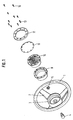
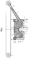
- the airbag steering wheel shown consists of a steering wheel rim 1, which three steering wheel spokes 2 is connected to a cup-shaped hub 3.
- the bottom of the Hub 3 has a central bore in a known manner, which with a spline is provided.
- the hub 3 is on the with a corresponding spline provided upper end of a steering shaft 4 plugged and with a nut 5 secured.
- At least one of the steering wheel spokes 2 is hollow to one To record gas generator 6.
- the gas generator 6 consists of an elongated one Housing containing a pyrotechnic propellant and an electrical ignition device contains. With the ignition device of the gas generator 6 is one with a plug contact provided connecting cable 7 connected by a in the bottom of the hub 3rd arranged bore 8 extends outwards.
- a housing 9 is inserted into the hub 3, which contains a folded airbag 10.
- the airbag 10 is on a side Opening of the housing 9 is tightly connected to the gas generator 6.
- the housing 9 has an annular flange for connection to a cover 11.
- a clamping ring 12 is with several screws 13 and lock nuts 14 with the flange of Housing 9 and the cover 11 clamped.
- the cover 11 is with a central recess, in which an ornament, such as a company emblem is inserted.
- the airbag 10 containing and closed with the cover 11 Housing 9 forms a structural unit together with gas generator 6. This unit is usually used by the motor vehicle manufacturer on airbag devices specialized supplier.
- the gas generator 6 When assembling the airbag, the gas generator 6 is first removed from the hub 3 ago inserted into the hollow steering wheel spoke 2. Following this is the housing 9 inserted into the hub 3, the connecting cable 7 through the bore 8 the hub is passed through. The connecting cable 7 is connected to a (not shown) Control unit connected. The clamping ring 12 is next to the receiving the screws 13 Provide holes with additional holes. Through these holes of the clamping ring 12 screws 16 in corresponding axial holes Screwed in hub 3 to firmly connect the housing 9 to the hub. To one To ensure proper connection of the housing 9 with the hub 3 should used a screwdriver with torque control to tighten the screws 16 become.
- the gas generator 6 is ignited by the control unit inflate the airbag 10. Under the pressure exerted by the airbag 10 Cover 11 blown open, so that the airbag emerge from the hub 3 and itself can fill quickly to protect the driver from an impact.
- a gas generator can be installed in each of the three steering wheel spokes 2 6 may be arranged.
- a slight Accident with a weak impact of the vehicle not all three gas generators, but only two or even one of them is ignited. It would also exist Possibility to trigger the gas generators in short intervals to complete the inflation process to optimize the airbag.
- the clamping ring is resiliently supported on the housing so that it closes a electrical contact for a bugle is actuated.
Landscapes
- Engineering & Computer Science (AREA)
- Mechanical Engineering (AREA)
- Air Bags (AREA)
- Steering Controls (AREA)
Abstract
Description
- 1
- Lenkradkranz
- 2
- Lenkradspeichen
- 3
- Nabe
- 4
- Lenkwelle
- 5
- Mutter
- 6
- Gasgenerator
- 7
- Anschlußkabel
- 8
- Bohrung
- 9
- Gehäuse
- 10
- Luftsack
- 11
- Abdeckung
- 12
- Klemmring
- 13
- Schrauben
- 14
- Gegenmuttern
- 15
- Verzierung
- 16
- Schrauben
Claims (4)
- Airbag-Lenkrad mit einer Nabe, die ein den gefalteten Luftsack enthaltendes Gehäuse aufnimmt, dadurch gekennzeichnet, daß der oder die Gasgeneratoren (6) vom Luftsack (10) räumlich getrennt und in eine oder mehrere Lenkradspeichen (2) und/oder in den Lenkradkranz (1) eingebaut sind.
- Airbag-Lenkrad nach Anspruch 1, gekennzeichnet durch den Einbau mehrerer Gasgeneratoren, die einzeln auslösbar sind.
- Airbag-Lenkrad nach Anspruch 1 oder 2, dadurch gekennzeichnet, daß eine Abdeckung (11) mit dem Gehäuse (9) über einen Klemmring (12) verschraubt ist, und daß die aus Gehäuse (9) Abdeckung (11) und Klemmring (12) bestehende Baueinheit mit der Nabe (3) verschraubt ist.
- Airbag-Lenkrad nach Anspruch 3, dadurch gekennzeichnet, daß sich der Klemmring am Gehäuse federnd abstützt und zum Schließen eines elektrischen Kontaktes für ein Signalhorn betätigbar ist.
Applications Claiming Priority (2)
| Application Number | Priority Date | Filing Date | Title |
|---|---|---|---|
| DE19940702 | 1999-08-27 | ||
| DE19940702A DE19940702A1 (de) | 1999-08-27 | 1999-08-27 | Airbag-Lenkrad |
Publications (2)
| Publication Number | Publication Date |
|---|---|
| EP1078824A1 true EP1078824A1 (de) | 2001-02-28 |
| EP1078824B1 EP1078824B1 (de) | 2004-10-20 |
Family
ID=7919818
Family Applications (1)
| Application Number | Title | Priority Date | Filing Date |
|---|---|---|---|
| EP00114381A Expired - Lifetime EP1078824B1 (de) | 1999-08-27 | 2000-07-05 | Airbag-Lenkrad mit vom Luftsack getrennten Gasgeneratoren |
Country Status (2)
| Country | Link |
|---|---|
| EP (1) | EP1078824B1 (de) |
| DE (2) | DE19940702A1 (de) |
Cited By (2)
| Publication number | Priority date | Publication date | Assignee | Title |
|---|---|---|---|---|
| US6820894B2 (en) * | 2002-12-04 | 2004-11-23 | Hyundai Mobis Co., Ltd. | Structure for installation a air-bag module on a steering wheel |
| WO2017037163A1 (de) * | 2015-09-02 | 2017-03-09 | Trw Automotive Safety Systems Gmbh | Lenkrad, gassackmodul für ein derartiges lenkrad, fahrzeug und montageverfahren |
Families Citing this family (4)
| Publication number | Priority date | Publication date | Assignee | Title |
|---|---|---|---|---|
| DE10331655A1 (de) * | 2003-07-12 | 2005-02-17 | Autoliv Development Ab | Airbag-Modul für Kraftfahrzeuge |
| DE10349537B4 (de) * | 2003-10-22 | 2006-03-16 | Autoliv Development Ab | Lenkrad für ein Kraftfahrzeug |
| US7234725B2 (en) * | 2004-05-28 | 2007-06-26 | Autoliv Asp, Inc. | Driver side airbag module assembly |
| DE102012006504A1 (de) * | 2012-03-29 | 2013-10-02 | GM Global Technology Operations LLC (n. d. Gesetzen des Staates Delaware) | Gasgenerator für eine Airbaganordnung eines Fahrzeugs und Fahrzeug mit der Airbaganordnung |
Citations (2)
| Publication number | Priority date | Publication date | Assignee | Title |
|---|---|---|---|---|
| US5066038A (en) * | 1990-07-31 | 1991-11-19 | Bendix Atlantic Inflator Company | Driver side hybrid inflator and air bag module |
| JPH09249088A (ja) * | 1996-03-14 | 1997-09-22 | Toyo Tire & Rubber Co Ltd | 運転席用エアバッグ装置 |
Family Cites Families (4)
| Publication number | Priority date | Publication date | Assignee | Title |
|---|---|---|---|---|
| US3506281A (en) * | 1967-10-06 | 1970-04-14 | Eaton Yale & Towne | Vehicle safety apparatus |
| DE19616977C1 (de) * | 1996-04-27 | 1997-04-10 | Autoliv Dev | Lenkrad mit integrierter Airbag-Einheit |
| DE19625722C2 (de) * | 1996-06-27 | 2000-05-11 | Autoliv Dev | Lenkrad mit schwimmend angeordnetem Airbagmodul |
| DE19631739C2 (de) * | 1996-08-06 | 2000-03-09 | Fkfs Forschungsinstitut Fuer K | Schutzvorrichtung für eine Person in einem Fahrzeug |
-
1999
- 1999-08-27 DE DE19940702A patent/DE19940702A1/de not_active Withdrawn
-
2000
- 2000-07-05 DE DE50008304T patent/DE50008304D1/de not_active Expired - Fee Related
- 2000-07-05 EP EP00114381A patent/EP1078824B1/de not_active Expired - Lifetime
Patent Citations (2)
| Publication number | Priority date | Publication date | Assignee | Title |
|---|---|---|---|---|
| US5066038A (en) * | 1990-07-31 | 1991-11-19 | Bendix Atlantic Inflator Company | Driver side hybrid inflator and air bag module |
| JPH09249088A (ja) * | 1996-03-14 | 1997-09-22 | Toyo Tire & Rubber Co Ltd | 運転席用エアバッグ装置 |
Non-Patent Citations (1)
| Title |
|---|
| PATENT ABSTRACTS OF JAPAN vol. 1998, no. 01 30 January 1998 (1998-01-30) * |
Cited By (2)
| Publication number | Priority date | Publication date | Assignee | Title |
|---|---|---|---|---|
| US6820894B2 (en) * | 2002-12-04 | 2004-11-23 | Hyundai Mobis Co., Ltd. | Structure for installation a air-bag module on a steering wheel |
| WO2017037163A1 (de) * | 2015-09-02 | 2017-03-09 | Trw Automotive Safety Systems Gmbh | Lenkrad, gassackmodul für ein derartiges lenkrad, fahrzeug und montageverfahren |
Also Published As
| Publication number | Publication date |
|---|---|
| EP1078824B1 (de) | 2004-10-20 |
| DE50008304D1 (de) | 2004-11-25 |
| DE19940702A1 (de) | 2001-03-01 |
Similar Documents
| Publication | Publication Date | Title |
|---|---|---|
| DE68923185T2 (de) | Luftsackrückhaltevorrichtung. | |
| EP0691245B1 (de) | Fahrzeuglenkrad für die Bestückung mit einem integrierten Gassack-Rückhaltesystem | |
| DE69204247T2 (de) | In der Lenkradabdeckung integrierter Hupenschalter mit verstärkender fester Struktur. | |
| DE4113591A1 (de) | Lenkrad mit einem luftsacksystem | |
| DE19521937A1 (de) | Sicherheitsvorrichtung | |
| EP0945311A2 (de) | Aufprall-Schutzvorrichtung | |
| DE19581552B4 (de) | Lenkrad mit vormontiertem Airbagmodul | |
| DE102017129248A1 (de) | Vorrichtung zum trennen einer fahrzeugtür in einem notfall | |
| EP0819585B1 (de) | Vorrichtung zum Aufblasen eines in einem Lenkrad untergebrachten Airbags | |
| EP1078824B1 (de) | Airbag-Lenkrad mit vom Luftsack getrennten Gasgeneratoren | |
| DE19508533C2 (de) | Airbagmodul für Kraftfahrzeuge | |
| DE19717629A1 (de) | Lenkrad mit Airbagmodul | |
| DE4400113C2 (de) | Airbagmodul für ein Kraftfahrzeug | |
| US5641178A (en) | Air bag device | |
| EP1075640B1 (de) | Notausstieg für sicherheitsfahrzeuge | |
| EP0769424A2 (de) | Baugruppe aus einem Lenkrad, einer Lenkwelle sowie einem Gasgenerator | |
| EP1060946B1 (de) | Lenkstockschaltermodul | |
| DE19545077A1 (de) | Vorrichtung zum Aufblasen eines Airbags (II) | |
| DE10260475B4 (de) | Verfahren zur Entsorgung von Kraftfahrzeug-Insassenschutzeinrichtungen sowie Vorrichtung hierfür | |
| EP0521850B1 (de) | Anordnung zur anbringung eines airbag in einem fahrzeuglenkrad | |
| EP1715195B1 (de) | Pyrotechnische Einheit für ein Sicherheitssystem, insbesondere eines Airbags oder eines Gurtstraffers eines Fahrzeugs | |
| DE4329120A1 (de) | Lenkrad für Kraftfahrzeuge | |
| EP0849124B1 (de) | Fahrzeuglenkrad mit Airbagmodul | |
| EP1249373B1 (de) | Lenksäule für Kraftfahrzeuge | |
| DE19732711A1 (de) | Sicherheitssysteme für Fahrzeugräder sowie Fahrzeugrad mit einem solchen System |
Legal Events
| Date | Code | Title | Description |
|---|---|---|---|
| PUAI | Public reference made under article 153(3) epc to a published international application that has entered the european phase |
Free format text: ORIGINAL CODE: 0009012 |
|
| AK | Designated contracting states |
Kind code of ref document: A1 Designated state(s): DE FR GB SE |
|
| AX | Request for extension of the european patent |
Free format text: AL;LT;LV;MK;RO;SI |
|
| 17P | Request for examination filed |
Effective date: 20010111 |
|
| AKX | Designation fees paid |
Free format text: DE FR GB SE |
|
| GRAP | Despatch of communication of intention to grant a patent |
Free format text: ORIGINAL CODE: EPIDOSNIGR1 |
|
| GRAS | Grant fee paid |
Free format text: ORIGINAL CODE: EPIDOSNIGR3 |
|
| GRAA | (expected) grant |
Free format text: ORIGINAL CODE: 0009210 |
|
| AK | Designated contracting states |
Kind code of ref document: B1 Designated state(s): DE FR GB SE |
|
| REG | Reference to a national code |
Ref country code: GB Ref legal event code: FG4D Free format text: NOT ENGLISH |
|
| REF | Corresponds to: |
Ref document number: 50008304 Country of ref document: DE Date of ref document: 20041125 Kind code of ref document: P |
|
| REG | Reference to a national code |
Ref country code: SE Ref legal event code: TRGR |
|
| PGFP | Annual fee paid to national office [announced via postgrant information from national office to epo] |
Ref country code: GB Payment date: 20050629 Year of fee payment: 6 |
|
| PGFP | Annual fee paid to national office [announced via postgrant information from national office to epo] |
Ref country code: SE Payment date: 20050706 Year of fee payment: 6 |
|
| PGFP | Annual fee paid to national office [announced via postgrant information from national office to epo] |
Ref country code: FR Payment date: 20050728 Year of fee payment: 6 |
|
| PLBE | No opposition filed within time limit |
Free format text: ORIGINAL CODE: 0009261 |
|
| STAA | Information on the status of an ep patent application or granted ep patent |
Free format text: STATUS: NO OPPOSITION FILED WITHIN TIME LIMIT |
|
| ET | Fr: translation filed | ||
| 26N | No opposition filed |
Effective date: 20050721 |
|
| PG25 | Lapsed in a contracting state [announced via postgrant information from national office to epo] |
Ref country code: DE Free format text: LAPSE BECAUSE OF NON-PAYMENT OF DUE FEES Effective date: 20060201 |
|
| PG25 | Lapsed in a contracting state [announced via postgrant information from national office to epo] |
Ref country code: GB Free format text: LAPSE BECAUSE OF NON-PAYMENT OF DUE FEES Effective date: 20060705 |
|
| PG25 | Lapsed in a contracting state [announced via postgrant information from national office to epo] |
Ref country code: SE Free format text: LAPSE BECAUSE OF NON-PAYMENT OF DUE FEES Effective date: 20060706 |
|
| EUG | Se: european patent has lapsed | ||
| GBPC | Gb: european patent ceased through non-payment of renewal fee |
Effective date: 20060705 |
|
| REG | Reference to a national code |
Ref country code: FR Ref legal event code: ST Effective date: 20070330 |
|
| PG25 | Lapsed in a contracting state [announced via postgrant information from national office to epo] |
Ref country code: FR Free format text: LAPSE BECAUSE OF NON-PAYMENT OF DUE FEES Effective date: 20060731 |