EP1078602A2 - Aiguille de suture à usage médical - Google Patents
Aiguille de suture à usage médical Download PDFInfo
- Publication number
- EP1078602A2 EP1078602A2 EP00118045A EP00118045A EP1078602A2 EP 1078602 A2 EP1078602 A2 EP 1078602A2 EP 00118045 A EP00118045 A EP 00118045A EP 00118045 A EP00118045 A EP 00118045A EP 1078602 A2 EP1078602 A2 EP 1078602A2
- Authority
- EP
- European Patent Office
- Prior art keywords
- needle
- suturing needle
- suturing
- medical use
- body portion
- Prior art date
- Legal status (The legal status is an assumption and is not a legal conclusion. Google has not performed a legal analysis and makes no representation as to the accuracy of the status listed.)
- Withdrawn
Links
Images


Classifications
-
- A—HUMAN NECESSITIES
- A61—MEDICAL OR VETERINARY SCIENCE; HYGIENE
- A61B—DIAGNOSIS; SURGERY; IDENTIFICATION
- A61B17/00—Surgical instruments, devices or methods, e.g. tourniquets
- A61B17/04—Surgical instruments, devices or methods, e.g. tourniquets for suturing wounds; Holders or packages for needles or suture materials
- A61B17/06—Needles ; Sutures; Needle-suture combinations; Holders or packages for needles or suture materials
- A61B17/06066—Needles, e.g. needle tip configurations
-
- A—HUMAN NECESSITIES
- A61—MEDICAL OR VETERINARY SCIENCE; HYGIENE
- A61B—DIAGNOSIS; SURGERY; IDENTIFICATION
- A61B17/00—Surgical instruments, devices or methods, e.g. tourniquets
- A61B17/04—Surgical instruments, devices or methods, e.g. tourniquets for suturing wounds; Holders or packages for needles or suture materials
- A61B17/06—Needles ; Sutures; Needle-suture combinations; Holders or packages for needles or suture materials
- A61B17/06004—Means for attaching suture to needle
Definitions
- the present invention relates to a suturing needle for medical use having an improved bending strength and a reduced piercing resistance.
- a suturing needle for medical use is manipulated by a surgeon with a needle holder for clamping the needle, and the needle has a function of piercing an affected part of a body to pass a suture through the affected part.
- various kinds of the suturing needles for medical use with different configurations and sizes have been provided, and a suitable needle is selected among the suturing needles for medical use and is used according to the affected part to be sutured.
- the suturing needle for medical use has a sharp needle tip at a tip end of the needle and has a needle tip portion formed at a predetermined distance from the needle tip, and the needle tip portion has, in sequence, a body portion and a distal end portion.
- a thickness of the needle tip portion has gradually increased from the sharp needle tip to the body portion, and each of the suturing needles for medical use has its own cross-sectional configuration.
- a cross-sectional configuration of a needle tip portion may be polygonal, where a plurality of edges constituting the polygonal configuration form cutting edges; or a cross-sectional configuration may be circular with no cutting edges.
- the suturing needle for medical use with the cutting edge has a function of piercing a tissue with the needle tip and tearing the tissue; on the other hand, the suturing needle for medical use without the cutting edge has a function of pressingly widening the tissue to which the needle tip has pierced.
- the body portion has a cross-sectional configuration extended from the cross section of the needle tip portion, or has a circular cross section, regardless of types of the cross-sectional configuration of the needle tip portion, and also the cross-sectional area of the body portion is constantly maintained.
- the suturing needle for medical use which even forms the cutting edge in the needle tip portion has no cutting edge in the body portion.
- the distal end portion is a portion to which a suture is coupled, and the distal end portion has a hole defined by a pair of hole supports having a spring property, or a blind hole formed in the distal end surface.
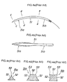
- a suturing needle for medical use disclosed in Japanese Unexamined Patent Publication (KOKAI) Showa No. 63-257539 is a spatulate suturing needle 51 structured for ophthalmic use as shown in Fig. 4.
- the cross section of a needle tip portion 51a is partially triangle shown in Fig. 4(c) and quadrangle shown in Fig. 4(d), and surfaces 52 constituting each of sides are formed as concave surfaces, and intersection of the above concaved surfaces forms each of ridgelines 53 as being acute.
- each of the ridgelines 53 has a highly acute angle of a cutting edge or an angle according to the cuffing edge. According to the above spatulate suturing needle 51, since the acute ridgeline 53 passes through the tissue along the portion cut by the edge of the needle tip portion 51a, the portion thus injured can be reduced, and since contacting of the concave surface 52 with the tissue is reduced, the piercing resistance can be lowered.
- a suturing needle 61 for medical use disclosed in Japanese Utility Model Publication (KOKAI) Showa No. 56-61212 is a needle where several convex portions 62 and concave portions 63 are alternately formed from a needle tip portion 61 a toward a needle body portion 61 b as shown in Fig. 5.
- the convex portions 62 and the concave portions 63 are corresponded with convex portions and concave portions formed in a needle holder (not shown) to be grasped, suturing operation can be made in a stable state.
- the needle becomes a cantilever bar where the portion to be clamped by the needle holder is served as a supporting portion and the needle tip portion is served as a loading portion, and therefore, a large flexure is produced in the portion clamped by the needle holder, with the result that the suturing operation may suffer.
- the respective suturing needles for medical use as mentioned above do not solve such a problem, and consequently, the idea of reducing the flexure is not disclosed.
- the present invention provides a suturing needle for medical use (hereinafter referred to simply as a "suturing needle”) having a needle tip portion piercing a body tissue; a distal end portion to which a suture is coupled; and a body portion formed between the needle tip portion and the distal end portion, in which at least the body portion is constituted of a pair of surfaces opposing to each other, and a pair of grooves opposing to each other in a direction intersecting with the opposing to direction of the mentioned surfaces.
- a cross-sectional configuration of the body portion or a cross-sectional configuration from the body portion to the needle tip portion is formed by combining a pair of surfaces opposing to each other, with concave grooves formed in a direction perpendicular to the pair of surfaces.
- the aforementioned suturing needle is a curved needle having, as side surfaces, the pair of grooves, where a user manipulates a curved needle of the same kind with a snapping movement
- the effect by the geometrical moment of inertia as mentioned above can be further advantageously utilized.
- the great advantage can be further obtained, when a relation between a width B and a height H of the cross section of the above body portion is B/H ⁇ 1 where a curving direction of the mentioned suturing needle is set as a reference.
- Each of the pair of surfaces opposing to each other may be a flat surface, a surface slightly convexed toward an outer periphery, or a surface slightly concaved toward the center. These surfaces are desirably formed in a process of manufacturing the suturing needle by a plastic processing, so as to increase a work hardening coefficient.
- the suturing needle desirably has a curved surface with no edge respectively for the mentioned pair of grooves, and a curved surface for a connecting portion formed between the mentioned surface and the mentioned groove.
- the cross-sectional contour of the above connecting portion is desirably formed by a curved line having a radius in a range from 10 % to 25 % of a diameter of the thickest portion of the suturing needle.
- the thickest portion mentioned above is a connecting portion or its vicinity between the body portion and the distal end portion in the case of the suturing needle having a blind hole in the distal end surface, or the thickest portion is a portion near the center of the body portion in the case of the suturing needle having a pair of hole supports in the distal end portion.
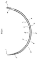
- Fig. 1 is an illustration explaining a structure of a suturing needle.
- Fig. 2 is a cross-sectional view taken along line II-II in Fig. 1 for explaining a cross-sectional configuration of the body portion.
- Fig. 3 is an explanation view of a die used for the press working of the suturing needle.
- a tissue is first pierced by a sharp needle tip 1 of a suturing needle A shown in Fig. 1 and Fig. 2, the portion thus pierced is pressingly widen by a needle tip portion 2 formed sequentially to the needle tip 1, and while the tissue is kept in a state of being pressingly widen, a body portion 3 and a distal end portion 4 of the needle pass through the tissue, with the result that a suture (not shown) coupled to the distal end portion 4 can pass through the tissue.
- the suturing needle A does not tear the tissue, the suturing needle A is used mainly for suturing blood vessels.
- both the side surfaces of the body portion 3 or of the portion from the needle tip portion 2 to the body portion 3 of the suturing needle A have concave grooves 5, which can increase considerably the geometrical moment of inertia, although the body portion 3 has a cross-sectional area that is the same as that of an original circle.
- the suturing needle A is formed as a curved needle having a radius of curvature and a bending angle previously set with respect to the portion from the needle tip 1 through to the distal end portion 4.
- the suturing needle according to the present invention is not limited to the aforementioned suturing needle A (where the needle tip portion 2 has a circular cross section), and even the suturing needles having other cross-sectional configurations can be applied.
- a suturing needle as forming a cutting edge at the needle tip portion can have a configuration of the body portion that is the same as that of the present embodiment, irrespective of the cross-sectional configuration of the needle tip portion.
- the suturing needle A is not necessarily a curved needle, and a straight suturing needle can be applied.
- the thickness of the suturing needle is typically in a range from 0.025 mm to 1.40 mm, and the suturing needle having the mentioned thickness is selected and utilized by the surgeon according to the portions to be sutured.
- the suturing needle A for example, for suturing the blood vessel as that in the present embodiment, there are a variety of the suturing needles A, to be employed, having different diametral thicknesses according to the diametral thickness and the thickness of the blood vessel to be sutured, different radii of curvature, and different bending angles.
- the needle tip portion 2 formed as a conical-shaped taper along the portion from the needle tip 1 to the body portion 3, has a function of pressingly widening the tissue to which the needle tip 1 has pierced, without tearing the tissue, and the needle tip portion 2 has a circular cross section in sequence from the sharp needle tip 1 formed at the tip end, or a Japanese drum-shape cross section explained below, mentioned later, from the vicinity of the body portion 3 to the body portion, in which the cross-sectional area increases as the distance from the needle tip 1 increases.
- the body portion 3 is a portion clamped by the needle holder (not shown) in a stable state when the affected part is to be sutured, where the cross-sectional configuration has a drum shape in which the upper portion projects laterally; the middle portion recedes; and the lower portion again projects laterally, as shown in Fig. 2.
- the cross-sectional area of the body portion is maintained approximately at a predetermined value even when the distance from the needle tip 1 is changed.
- the distal end portion 4 has a function of coupling a suture (not shown) thereto, where, after an end of the suture is inserted into a blind hole formed in a predetermined depth from the end surface side, the suture can be coupled thereto by caulking the circumference of the blind hole, or the suture can be coupled to the distal end portion 4 by a hook-shaped slip stopper piece formed at a position opposite to a pair of protruding hole supports having a spring property.
- the suturing needle A is formed as a so-called eyeless needle forming a blind hole 4a in the end surface of the distal end portion 4.
- the body portion 3 has, as a pair of flat surfaces 6, surfaces opposing to each other formed respectively on an inside diameter side and an outside diameter side of the curvature, and has, as a pair of concave grooves 5, both of the side surfaces of the curvature, each of the side surfaces being concaved toward the center of the body portion 3.
- a connecting portion 7 between the flat surface 6 and the groove 5 is formed by a curved surface having a radius in a range from 10 % to 25 % of a diameter of the thickest portion of the suturing needle A, and the connecting portion 7 connects smoothly the flat surface 6 to the groove 5 consisting of the concave surface, so as to make the whole structure a shape similar to a shoulder drum (drum shape).
- a needle holder can hold the suturing needle with good stability.
- the connecting portion 7 between the flat surface 6 and the groove 5 is not necessarily a curved surface, but may be formed in a polygonal shape consisting of a lot of straight lines sequentially provided. Also in this case, the apparent radius of curvature of the polygonal shape is preferably in a range from 10 % to 25 % of a diameter of the thickest portion of the suturing needle A.
- the cross-sectional area is not changed along the whole length of the body portion 3, and is a value approximately the same as that of the material constituting the suturing needle A.
- a ratio of the width size B of the flat surface 6 to the distance H (height size) between the flat surfaces 6 is not especially limited, but the ratio of B to H (B/H) is preferably 1 or less. The ratio of 1 or less can make the value of the geometrical moment of inertia larger. Also the ratio of B to H (B/H) is equals to 0.7 or more. If the ratio is less than 0.7, the suturing needle lacks stability when it is held with the needle holder.
- the width size B of the flat surface 6 is set smaller than a diameter of the circle, while the height size H is set larger than the diameter of the circle.
- the shape of the groove 5 includes a V shape with a gentle bottom surface, an arc shape or the like, and when the arc shape is used, the radius of curvature is preferably around 15 % to 45 % of a diameter of the thickest portion of the suturing needle A.
- a diameter of the thickest portion is 0.45 mm; a width size B of the flat surface 6 and a height H between the flat surfaces 6 are respectively set 0.381 mm and 0.470 mm; and the radius of curvature of the groove 5 is 0.150 mm.
- a piercing resistance becomes lowered.
- the suturing needle A of the present embodiment had a piercing resistance of 100 g, while the conventional suturing needle had a piercing resistance of 110 g.
- the result of bending tests using the suturing needle A of the present embodiment shows that the suturing needle A was able to improve the strength approximately 1.4 times the strength of the conventional needle having a body portion with a circular cross section as well as having the value of the thickest portion which is the same as that of the suturing needle A.
- the result of 90-degree bending tests where the needle is repeatedly bent at a 90 degree in the direction of an outside diameter of the curvature, shows that the suturing needle A was able to endure the number of bending times (three times) which is the same as that of the needle having a body portion with a circular cross section as well as having the value of the thickest portion which is the same as that of the suturing needle.
- the suturing needle was fractured by second time of the bending operation.
- the needle is required to have each of the flat surfaces 6 opposing to each other as well as a pair of the concave grooves 5, and is required to connect these surfaces to the grooves through the connecting portion 7 formed of a curved surface.
- the suturing needle A is required to have a sufficient hardness and to be prevented from having rust and corrosion, in order to pierce the tissue when suturing the affected part. Consequently, in the present embodiment, an austenitic stainless steel is used as a material, where a wire material having a diameter previously set in consideration of the processing rate is subjected to a cold wiredrawing processing, and then the diameter is reduced to obtain a desired diameter of the suturing needle A.
- the wire thus obtained according to the step mentioned above has fibrously extended austenitic texture in the material, and therefore the wire can gain a high hardness due to work hardening and a high flexibility due to the fibrous texture.
- the austenitic stainless steel is used for the material, the material can be prevented from having rust because a high anti-corrosive property is provided, and also the material can be adequately flexible.
- the above material is cut to have a desired length of the suturing needle A, and is processed to be a straight material.
- One of the end portions of the material is polished to form the needle tip 1 and the needle tip portion 2 of a conical shaped taper.
- a press step for an intermediate material subjected to cold wiredrawn is shown in Fig. 3.
- the press step utilizes a press die 30 including divided 4 pieces.
- the press die 30 consists of a top piece 30A, a bottom piece 30B, a left piece 30C and a right piece 30D, each having a shape where a cross section has an approximately triangle tip constituted of two lines 30a, 30b which intersect at a 90 degree.
- each of the top piece 30A and the bottom piece 30B has a flat surface portion 30X, while the tip end of each of the left piece 30C and right piece 30D has respectively a projecting portion 30Y having a shape of circular arc.
- the adjacent lines of 30a, 30b of the respective dies are joined to form, in the center, a space S having flat top and bottom surfaces and concave side surfaces (See, Fig. 3(b)).
- the top piece 30A and the bottom piece 30B are used to sandwich and hold, vertically, the intermediate material P with both the flat surface portions of the pieces thus used, so as not to move the intermediate material P.
- the respective projecting portions 30Y in a circular arc shape push the intermediate material P to deform the cross sectional configuration of the intermediate material P.
- the intermediate material P thus deforming along the configuration of the space S, is then formed as a suturing needle having flat surfaces 6 on the top and bottom surfaces and grooves 5 on the left and right side surfaces.
- the press die 30 is constituted of the piece 30A, 30B, 30C and 30D each having the configuration mentioned above, when the pieces 30A, 30B, 30C, and 30D are respectively subjected to the mold clamping, applying forces from the four sides are balanced on the lines 30a, 30b adjacent between the respective pieces 30A, 30B, 30C and 30D, and pushing force of the projecting portions 30Y are constantly maintained.
- stable deforming processing can be constantly performed with respect to the intermediate material P without pressing excessive force thereto.
- the distal end portion 4 is formed at an end portion on the other side of the above needle portion. That is, the end surface on the other side of the needle portion of the material is melted by radiation of laser light, and is then evaporated to form the blind hole 4a, or the end surface is subjected to drill processing to form the blind hole 4a, thereby forming the distal end portion 4 at the end portion.
- the flat surfaces 6 are disposed respectively on the side of the inside diameter and on the side of the outside diameter of the curvature, and then are subjected to a bending molding to curve for obtaining the desired radius of curvature and angle of the suturing needle A, thereby producing the suturing needle A.
- a portion from the needle tip 1 to the body portion 3 of the suturing needle A thus obtained is a fibrously extended austenitic texture, thereby having a high hardness and a high flexibility. As a result, tissue of the affected part can be pierced extremely easily in suturing the affected part.
- the suturing needle for medical use of the present invention is explained as a curved needle according to the present embodiment
- the suturing needle A for medical use having the grooves 5 on the both side surfaces and the flat surfaces 6 on the top and bottom surfaces has a smaller contacting area with the body tissue, thereby obtaining such an effect as reducing the piercing resistance; as a result, when applying to a straight needle which is not curved, the suturing needle can gain the given effect.
- the aforementioned embodiment is explained as a suturing needle for medical use having the flat surfaces 6 on the top and bottom surfaces, but the suturing needle for medical use according to the present invention is not limited to this; a suturing needle having curved surfaces on the top and bottom surfaces may be used.
- the configuration of the groove 5 may be a V-shaped type, a rectangularly letter U-shaped type or other type in various shapes, a groove which does not form edges as shown in the present embodiment can provide a high ductility.
- the groove 5 is formed in a portion from the body portion 3 to the needle tip portion 2 according to the present embodiment, such a structure as having the groove only in the body portion 3 may be used.
- the body portion of the suturing needle according to the present invention is constituted of a pair of surfaces opposing to each other, as well as, a pair of grooves concaved toward the center in which the groove intersects with the surface, when the pair of the surfaces are disposed on the top and bottom sides, a value of the geometrical moment of inertia becomes large, thus to be able to show a high strength with respect to bending movement.
- the groove is formed in a shape concaved toward the center of the body portion, the contacting area with the body tissue can be smaller during the piercing operation, thereby achieving in reducing the piecing resistance.
- the pair of the surfaces and the pair of the grooves are connected by the curved surface having a value of the radius of curvature in a range from 10 % to 25 % of a diameter of the thickest portion of the suturing needle, concentration of the bending stress is not given, thereby achieving a strong suturing needle with respect to bending movements.
Applications Claiming Priority (2)
| Application Number | Priority Date | Filing Date | Title |
|---|---|---|---|
| JP23965399 | 1999-08-26 | ||
| JP23965399 | 1999-08-26 |
Publications (2)
| Publication Number | Publication Date |
|---|---|
| EP1078602A2 true EP1078602A2 (fr) | 2001-02-28 |
| EP1078602A3 EP1078602A3 (fr) | 2001-04-04 |
Family
ID=17047913
Family Applications (1)
| Application Number | Title | Priority Date | Filing Date |
|---|---|---|---|
| EP00118045A Withdrawn EP1078602A3 (fr) | 1999-08-26 | 2000-08-23 | Aiguille de suture à usage médical |
Country Status (2)
| Country | Link |
|---|---|
| US (1) | US6322581B1 (fr) |
| EP (1) | EP1078602A3 (fr) |
Cited By (2)
| Publication number | Priority date | Publication date | Assignee | Title |
|---|---|---|---|---|
| EP1634535A1 (fr) * | 2004-09-13 | 2006-03-15 | Mani, Inc. | Aiguille à usage médical et outil coupant |
| CN101513356A (zh) * | 2001-06-14 | 2009-08-26 | 苏太克股份有限公司 | 外科线缝合的设备和方法 |
Families Citing this family (74)
| Publication number | Priority date | Publication date | Assignee | Title |
|---|---|---|---|---|
| US8795332B2 (en) | 2002-09-30 | 2014-08-05 | Ethicon, Inc. | Barbed sutures |
| US5931855A (en) | 1997-05-21 | 1999-08-03 | Frank Hoffman | Surgical methods using one-way suture |
| DE19962421C1 (de) * | 1999-12-22 | 2001-06-07 | Roland Man Druckmasch | Verfahren und Vorrichtung zum Kuppeln/Entkuppeln eines Zylinders in einer Druckmaschine |
| JP2002294571A (ja) * | 2001-03-30 | 2002-10-09 | Kuraray Co Ltd | 難燃性皮革様シート基体およびその製造方法 |
| US7056331B2 (en) | 2001-06-29 | 2006-06-06 | Quill Medical, Inc. | Suture method |
| US20040002724A1 (en) * | 2002-05-23 | 2004-01-01 | Falahee Mark H. | Navigable trocar with safety tip |
| AU2003256541A1 (en) * | 2002-07-17 | 2004-02-02 | Tyco Healthcare Group Lp | Union stress needle |
| US8062332B2 (en) * | 2002-07-17 | 2011-11-22 | Tyco Healthcare Group Lp | Surgical cobra head suture needle |
| US7655024B2 (en) | 2002-07-17 | 2010-02-02 | Tyco Healthcare Group Lp | Surgical suture needle |
| US6773450B2 (en) | 2002-08-09 | 2004-08-10 | Quill Medical, Inc. | Suture anchor and method |
| US20040088003A1 (en) | 2002-09-30 | 2004-05-06 | Leung Jeffrey C. | Barbed suture in combination with surgical needle |
| AU2003277263B2 (en) * | 2002-10-04 | 2008-12-04 | Covidien Lp | Sharpoint needle |
| SI1413253T1 (sl) * | 2002-10-25 | 2006-02-28 | Somatex Medical Technologies Gmbh | Drzalo biopta za biopsijo z debelo iglo |
| US20040133124A1 (en) * | 2003-01-06 | 2004-07-08 | Cook Incorporated. | Flexible biopsy needle |
| US7344554B2 (en) * | 2003-02-26 | 2008-03-18 | Ams Research Corporation | Keith needle for furlow insertion tool |
| US7185524B2 (en) * | 2003-08-14 | 2007-03-06 | Tyco Healthcare Group Lp | Grindless surgical needle manufacture |
| TWI233341B (en) * | 2003-09-26 | 2005-06-01 | Cheng-Kun Chen | Improved structure of tattooing needle and eyebrow lining needle |
| WO2005032428A1 (fr) * | 2003-10-02 | 2005-04-14 | Ams Research Corporation | Dispositifs de prothese penienne |
| US6926720B2 (en) * | 2003-10-15 | 2005-08-09 | Hand Innovations, Llc | Jig assembly for implantation of a fracture fixation device |
| US7353683B2 (en) | 2004-02-20 | 2008-04-08 | Tyco Healthcare Group Lp | Surgical needle manufacturing process |
| ES2541680T3 (es) | 2004-03-06 | 2015-07-23 | F. Hoffmann-La Roche Ag | Dispositivo de muestreo de líquidos corporales |
| US7819822B2 (en) * | 2004-03-06 | 2010-10-26 | Roche Diagnostics Operations, Inc. | Body fluid sampling device |
| RU2404717C2 (ru) | 2004-05-14 | 2010-11-27 | Квилл Медикал, Инк. | Способы и устройства для наложения швов |
| US20060047309A1 (en) * | 2004-08-25 | 2006-03-02 | Cichocki Frank R Jr | Metal injection molded suture needles |
| US8123764B2 (en) | 2004-09-20 | 2012-02-28 | Endoevolution, Llc | Apparatus and method for minimally invasive suturing |
| US9775600B2 (en) | 2010-10-01 | 2017-10-03 | Endoevolution, Llc | Devices and methods for minimally invasive suturing |
| US7976555B2 (en) | 2008-07-17 | 2011-07-12 | Endoevolution, Llc | Apparatus and method for minimally invasive suturing |
| US8292920B2 (en) | 2005-11-10 | 2012-10-23 | Tyco Healthcare Group Lp | Sickle needle and method |
| EP1981406B1 (fr) | 2006-01-27 | 2016-04-13 | Suturtek Incorporated | Dispositif de fermeture de tissu |
| US7415858B2 (en) | 2006-02-21 | 2008-08-26 | Tyco Healthcare Group Lp | Grindless surgical needle manufacture |
| US7591716B2 (en) * | 2006-06-02 | 2009-09-22 | Ethicon Endo-Surgery, Inc. | Producing notch feature in small diameter steel alloy needle wire |
| DE102006044788A1 (de) * | 2006-09-13 | 2008-03-27 | Aesculap Ag & Co. Kg | Chirurgische Nadel und Verfahren zum Herstellen einer chirurgischen Nadel |
| US8915943B2 (en) | 2007-04-13 | 2014-12-23 | Ethicon, Inc. | Self-retaining systems for surgical procedures |
| EP2712555B1 (fr) * | 2007-05-29 | 2017-08-23 | Ethicon LLC | Emballage de suture |
| WO2009036060A2 (fr) | 2007-09-10 | 2009-03-19 | Angiotech Pharmaceuticals, Inc. | Conditionnement de suture et procédés associés |
| JP5518737B2 (ja) | 2007-12-19 | 2014-06-11 | エシコン・エルエルシー | 熱接触媒介リテーナを備えた留置縫合糸 |
| US8118834B1 (en) | 2007-12-20 | 2012-02-21 | Angiotech Pharmaceuticals, Inc. | Composite self-retaining sutures and method |
| US9125647B2 (en) | 2008-02-21 | 2015-09-08 | Ethicon, Inc. | Method and apparatus for elevating retainers on self-retaining sutures |
| US8641732B1 (en) | 2008-02-26 | 2014-02-04 | Ethicon, Inc. | Self-retaining suture with variable dimension filament and method |
| BRPI0911132B8 (pt) | 2008-04-15 | 2021-06-22 | Angiotech Pharm Inc | sutura para ser usada em um procedimento aplicado ao tecido |
| US20110112575A1 (en) * | 2008-04-30 | 2011-05-12 | Mani, Inc. | Medical Suture Needle |
| US8961560B2 (en) | 2008-05-16 | 2015-02-24 | Ethicon, Inc. | Bidirectional self-retaining sutures with laser-marked and/or non-laser marked indicia and methods |
| BRPI0921810B8 (pt) | 2008-11-03 | 2021-06-22 | Angiotech Pharm Inc | montagem para inserir um comprimento de sutura no interior do corpo de um mamífero |
| EP2471467A4 (fr) * | 2009-08-28 | 2014-12-24 | Mani Inc | Aiguille de suture médicale |
| JP5823498B2 (ja) | 2010-04-29 | 2015-11-25 | エシコン・エルエルシーEthicon, LLC | 高密度自己保持縫合糸、その製造装置及び方法 |
| KR101883143B1 (ko) | 2010-05-04 | 2018-07-31 | 에티컨, 엘엘씨 | 자가-유지형 봉합재를 생성하기 위한 레이저 커팅 시스템 및 방법 |
| BR112012031606B1 (pt) | 2010-06-11 | 2020-11-10 | Ethicon Llc | distribuidor de sutura |
| AU2011323299B2 (en) | 2010-11-03 | 2016-06-30 | Ethicon Llc | Drug-eluting self-retaining sutures and methods relating thereto |
| EP2637574B1 (fr) | 2010-11-09 | 2016-10-26 | Ethicon, LLC | Sutures autostatiques d'urgence |
| WO2012068005A1 (fr) * | 2010-11-15 | 2012-05-24 | Ethicon Endo-Surgery, Inc. | Aiguille pour dispositif de suture laparoscopique |
| RU2659454C2 (ru) | 2011-03-23 | 2018-07-02 | ЭТИКОН ЭлЭлСи | Самоудерживающиеся нити с регулируемой петлей |
| US20130172931A1 (en) | 2011-06-06 | 2013-07-04 | Jeffrey M. Gross | Methods and devices for soft palate tissue elevation procedures |
| US9572566B2 (en) | 2012-02-29 | 2017-02-21 | Marker Medical, Llc | Surgical suturing apparatus and method |
| WO2013165942A1 (fr) | 2012-05-01 | 2013-11-07 | Brigham And Women's Hospital, Inc. | Dispositif de suture pour des interventions laparoscopiques |
| US9427227B2 (en) | 2012-12-13 | 2016-08-30 | Ethicon Endo-Surgery, Llc | Suturing device with reusable shaft and disposable cartridge |
| CN105455859B (zh) * | 2014-08-19 | 2019-09-06 | 马尼株式会社 | 医疗用缝合针 |
| CN104622627A (zh) * | 2015-02-10 | 2015-05-20 | 中国人民解放军第三军医大学第一附属医院 | 巩膜环扎带穿引器 |
| US20160346827A1 (en) * | 2015-05-26 | 2016-12-01 | Ethicon Endo-Surgery, Llc | Method of Fabricating a Surgical Needle with Recessed Features |
| KR101825878B1 (ko) * | 2017-05-12 | 2018-02-06 | 장철호 | 눈밑 지방 재배치 수술용 니들 기구 |
| WO2018119459A1 (fr) | 2016-12-23 | 2018-06-28 | Brigham And Women's Hospital, Inc. | Systèmes et procédés destinés à suturer un tissu |
| US20180242967A1 (en) | 2017-02-26 | 2018-08-30 | Endoevolution, Llc | Apparatus and method for minimally invasive suturing |
| US10292698B2 (en) | 2017-07-27 | 2019-05-21 | Endoevolution, Llc | Apparatus and method for minimally invasive suturing |
| USD920512S1 (en) | 2019-02-22 | 2021-05-25 | Ethicon, Inc. | Folded suture needle |
| USD937417S1 (en) | 2019-02-22 | 2021-11-30 | Ethicon, Inc. | Foldable suture needle |
| US11311288B2 (en) | 2019-02-22 | 2022-04-26 | Ethicon, Inc. | Suture needles having bendable regions |
| EP3927246A1 (fr) | 2019-02-22 | 2021-12-29 | Ethicon, Inc | Systèmes, dispositifs et procédés de fabrication d'aiguilles à suture très élastiques pour chirurgie mini-invasive |
| USD936828S1 (en) | 2019-02-22 | 2021-11-23 | Ethicon, Inc. | Bendable suture needle |
| US11696754B2 (en) | 2019-02-22 | 2023-07-11 | Ethicon, Inc. | Methods of making suture needles with localized regions for bending |
| USD895114S1 (en) | 2019-02-22 | 2020-09-01 | Ethicon, Inc. | Bent suture needle |
| USD938031S1 (en) * | 2019-07-14 | 2021-12-07 | Telma Micro Needles Pvt. Ltd. | Undrilled needle |
| US11559299B2 (en) | 2019-12-26 | 2023-01-24 | Trimed, Incorporated | Method and apparatus for directing an elongate flexible component through a part of a human body |
| USD965783S1 (en) * | 2020-06-22 | 2022-10-04 | Mani, Inc. | Knife for surgical purposes |
| JP2022025915A (ja) * | 2020-07-30 | 2022-02-10 | マニー株式会社 | 医療用縫合針 |
| US20220071621A1 (en) * | 2020-09-10 | 2022-03-10 | Ergosurgical Group Corp. | Tapered transition portion for suture needles |
Citations (6)
| Publication number | Priority date | Publication date | Assignee | Title |
|---|---|---|---|---|
| US2240330A (en) * | 1938-07-11 | 1941-04-29 | Andrew B Flagg | Surgical needle or the like |
| DE3712163A1 (de) * | 1987-04-10 | 1988-10-27 | Mo Nii Microchirurg | Atraumatische nadel |
| EP0582276A1 (fr) * | 1992-08-03 | 1994-02-09 | United States Surgical Corporation | Aquilles de fil de section non-circulaire |
| EP0597260A2 (fr) * | 1992-10-09 | 1994-05-18 | Ethicon, Inc. | Aiguille avec coupe en double T vraie |
| US5853423A (en) * | 1993-10-20 | 1998-12-29 | Ethicon, Inc. | Process for the manufacture of suture needles and needles produced thereby |
| US6019781A (en) * | 1998-10-16 | 2000-02-01 | Worland; Richard L. | Rotator cuff needle |
Family Cites Families (9)
| Publication number | Priority date | Publication date | Assignee | Title |
|---|---|---|---|---|
| US1599059A (en) * | 1925-09-09 | 1926-09-07 | Harry D Morton | Surgical needle and method of making the same |
| US2516710A (en) * | 1947-05-12 | 1950-07-25 | Delfino P Mascolo | Double point surgical needle |
| US3197997A (en) * | 1960-11-17 | 1965-08-03 | Leonard D Kurtz | Suture needle |
| US3160157A (en) * | 1962-03-29 | 1964-12-08 | Ethicon Inc | Surgical needle |
| US4524771A (en) * | 1982-10-28 | 1985-06-25 | Ethicon Inc. | Multiple curved surgical needle |
| JPS63257539A (ja) * | 1987-04-14 | 1988-10-25 | モスコフスキ ナウチノ−イススレドバテルスキインステイテユト ミクロヒルルギイ グラザ | 非外傷針 |
| US5002564A (en) * | 1989-06-19 | 1991-03-26 | Ethicon, Inc. | Surgical needle configuration with spatula geometry |
| US4932961A (en) * | 1989-09-15 | 1990-06-12 | Ethicon, Inc. | Surgical needle configuration with five-sided cross-section |
| JPH06296790A (ja) * | 1993-04-15 | 1994-10-25 | Matsutani Seisakusho Co Ltd | 医療用縫合針及び研削装置 |
-
2000
- 2000-08-23 EP EP00118045A patent/EP1078602A3/fr not_active Withdrawn
- 2000-08-24 US US09/644,745 patent/US6322581B1/en not_active Expired - Lifetime
Patent Citations (6)
| Publication number | Priority date | Publication date | Assignee | Title |
|---|---|---|---|---|
| US2240330A (en) * | 1938-07-11 | 1941-04-29 | Andrew B Flagg | Surgical needle or the like |
| DE3712163A1 (de) * | 1987-04-10 | 1988-10-27 | Mo Nii Microchirurg | Atraumatische nadel |
| EP0582276A1 (fr) * | 1992-08-03 | 1994-02-09 | United States Surgical Corporation | Aquilles de fil de section non-circulaire |
| EP0597260A2 (fr) * | 1992-10-09 | 1994-05-18 | Ethicon, Inc. | Aiguille avec coupe en double T vraie |
| US5853423A (en) * | 1993-10-20 | 1998-12-29 | Ethicon, Inc. | Process for the manufacture of suture needles and needles produced thereby |
| US6019781A (en) * | 1998-10-16 | 2000-02-01 | Worland; Richard L. | Rotator cuff needle |
Cited By (3)
| Publication number | Priority date | Publication date | Assignee | Title |
|---|---|---|---|---|
| CN101513356A (zh) * | 2001-06-14 | 2009-08-26 | 苏太克股份有限公司 | 外科线缝合的设备和方法 |
| EP1634535A1 (fr) * | 2004-09-13 | 2006-03-15 | Mani, Inc. | Aiguille à usage médical et outil coupant |
| US7662170B2 (en) | 2004-09-13 | 2010-02-16 | Mani, Inc. | Medical needle and cutting tool |
Also Published As
| Publication number | Publication date |
|---|---|
| US6322581B1 (en) | 2001-11-27 |
| EP1078602A3 (fr) | 2001-04-04 |
Similar Documents
| Publication | Publication Date | Title |
|---|---|---|
| US6322581B1 (en) | Suturing needle for medical use | |
| EP2425787B1 (fr) | Aiguille de suture | |
| EP0790036B1 (fr) | Aiguille comportant des tranchants concaves | |
| AU2003277263B2 (en) | Sharpoint needle | |
| US4513747A (en) | Hard tissue surgical needle | |
| US20180043419A1 (en) | Medical suture needle | |
| EP0627199B1 (fr) | Fixation d'une aiguille chirurgicale à un fil de suture pour séparation contrÔlée du fil de suture | |
| JP2000139931A (ja) | マイクロ縫合針およびその製造方法 | |
| US10575845B2 (en) | Suture needle | |
| JP4318110B2 (ja) | 医療用縫合針及び医療用縫合針の製造方法 | |
| CA2491025C (fr) | Aiguille a suture chirurgicale | |
| WO2021039743A1 (fr) | Aiguille de suture médicale | |
| JP2001333909A (ja) | 医療用縫合針 | |
| JP4482825B2 (ja) | 縫合針 | |
| JPH04282147A (ja) | 糸付アイレス縫合針及びカシメ型並びにカシメ型の製造方法 |
Legal Events
| Date | Code | Title | Description |
|---|---|---|---|
| PUAI | Public reference made under article 153(3) epc to a published international application that has entered the european phase |
Free format text: ORIGINAL CODE: 0009012 |
|
| PUAL | Search report despatched |
Free format text: ORIGINAL CODE: 0009013 |
|
| AK | Designated contracting states |
Kind code of ref document: A2 Designated state(s): CH DE ES FR GB IT LI |
|
| AX | Request for extension of the european patent |
Free format text: AL;LT;LV;MK;RO;SI |
|
| AK | Designated contracting states |
Kind code of ref document: A3 Designated state(s): AT BE CH CY DE DK ES FI FR GB GR IE IT LI LU MC NL PT SE |
|
| AX | Request for extension of the european patent |
Free format text: AL;LT;LV;MK;RO;SI |
|
| 17P | Request for examination filed |
Effective date: 20010907 |
|
| AKX | Designation fees paid |
Free format text: CH DE ES FR GB IT LI |
|
| 17Q | First examination report despatched |
Effective date: 20041018 |
|
| 17Q | First examination report despatched |
Effective date: 20041018 |
|
| STAA | Information on the status of an ep patent application or granted ep patent |
Free format text: STATUS: THE APPLICATION IS DEEMED TO BE WITHDRAWN |
|
| 18D | Application deemed to be withdrawn |
Effective date: 20070428 |