EP1078190B1 - Tige de forage a parois epaisses - Google Patents
Tige de forage a parois epaisses Download PDFInfo
- Publication number
- EP1078190B1 EP1078190B1 EP99920274A EP99920274A EP1078190B1 EP 1078190 B1 EP1078190 B1 EP 1078190B1 EP 99920274 A EP99920274 A EP 99920274A EP 99920274 A EP99920274 A EP 99920274A EP 1078190 B1 EP1078190 B1 EP 1078190B1
- Authority
- EP
- European Patent Office
- Prior art keywords
- drill pipe
- heavy weight
- weight drill
- tool joint
- psi
- Prior art date
- Legal status (The legal status is an assumption and is not a legal conclusion. Google has not performed a legal analysis and makes no representation as to the accuracy of the status listed.)
- Expired - Lifetime
Links
- 238000005452 bending Methods 0.000 claims description 26
- 230000001012 protector Effects 0.000 claims description 21
- 230000007797 corrosion Effects 0.000 claims description 19
- 238000005260 corrosion Methods 0.000 claims description 19
- 238000005336 cracking Methods 0.000 claims description 18
- 239000007788 liquid Substances 0.000 claims description 17
- UFHFLCQGNIYNRP-UHFFFAOYSA-N Hydrogen Chemical compound [H][H] UFHFLCQGNIYNRP-UHFFFAOYSA-N 0.000 claims description 16
- 229910052739 hydrogen Inorganic materials 0.000 claims description 16
- 239000001257 hydrogen Substances 0.000 claims description 16
- 238000000034 method Methods 0.000 claims description 16
- 230000035939 shock Effects 0.000 claims description 16
- 238000005496 tempering Methods 0.000 claims description 13
- 238000009863 impact test Methods 0.000 claims description 10
- 238000010791 quenching Methods 0.000 claims description 10
- 230000000171 quenching effect Effects 0.000 claims description 10
- 238000004891 communication Methods 0.000 claims description 3
- 238000003754 machining Methods 0.000 claims description 3
- 208000036366 Sensation of pressure Diseases 0.000 claims 1
- 239000000463 material Substances 0.000 description 36
- 238000001816 cooling Methods 0.000 description 5
- 229910000734 martensite Inorganic materials 0.000 description 5
- RWSOTUBLDIXVET-UHFFFAOYSA-N Dihydrogen sulfide Chemical compound S RWSOTUBLDIXVET-UHFFFAOYSA-N 0.000 description 4
- 229910001566 austenite Inorganic materials 0.000 description 4
- 229910000037 hydrogen sulfide Inorganic materials 0.000 description 4
- 229910000831 Steel Inorganic materials 0.000 description 3
- 230000006835 compression Effects 0.000 description 3
- 238000007906 compression Methods 0.000 description 3
- 238000005553 drilling Methods 0.000 description 3
- 239000012530 fluid Substances 0.000 description 3
- 239000010959 steel Substances 0.000 description 3
- CURLTUGMZLYLDI-UHFFFAOYSA-N Carbon dioxide Chemical compound O=C=O CURLTUGMZLYLDI-UHFFFAOYSA-N 0.000 description 2
- XEEYBQQBJWHFJM-UHFFFAOYSA-N Iron Chemical compound [Fe] XEEYBQQBJWHFJM-UHFFFAOYSA-N 0.000 description 2
- 230000001419 dependent effect Effects 0.000 description 2
- 238000004519 manufacturing process Methods 0.000 description 2
- 238000002791 soaking Methods 0.000 description 2
- XLYOFNOQVPJJNP-UHFFFAOYSA-N water Substances O XLYOFNOQVPJJNP-UHFFFAOYSA-N 0.000 description 2
- 229910000851 Alloy steel Inorganic materials 0.000 description 1
- 229910000975 Carbon steel Inorganic materials 0.000 description 1
- 229910045601 alloy Inorganic materials 0.000 description 1
- 239000000956 alloy Substances 0.000 description 1
- 239000004411 aluminium Substances 0.000 description 1
- XAGFODPZIPBFFR-UHFFFAOYSA-N aluminium Chemical compound [Al] XAGFODPZIPBFFR-UHFFFAOYSA-N 0.000 description 1
- 229910052782 aluminium Inorganic materials 0.000 description 1
- 229910001563 bainite Inorganic materials 0.000 description 1
- 239000012267 brine Substances 0.000 description 1
- 229910002092 carbon dioxide Inorganic materials 0.000 description 1
- 239000001569 carbon dioxide Substances 0.000 description 1
- 239000010962 carbon steel Substances 0.000 description 1
- 230000000694 effects Effects 0.000 description 1
- 229910052742 iron Inorganic materials 0.000 description 1
- 238000009533 lab test Methods 0.000 description 1
- 230000009972 noncorrosive effect Effects 0.000 description 1
- 229910001562 pearlite Inorganic materials 0.000 description 1
- 229920000642 polymer Polymers 0.000 description 1
- 238000012545 processing Methods 0.000 description 1
- 239000012858 resilient material Substances 0.000 description 1
- HPALAKNZSZLMCH-UHFFFAOYSA-M sodium;chloride;hydrate Chemical compound O.[Na+].[Cl-] HPALAKNZSZLMCH-UHFFFAOYSA-M 0.000 description 1
- 239000007779 soft material Substances 0.000 description 1
- 239000007787 solid Substances 0.000 description 1
- 239000006104 solid solution Substances 0.000 description 1
- 238000010561 standard procedure Methods 0.000 description 1
- 238000012360 testing method Methods 0.000 description 1
- 230000007704 transition Effects 0.000 description 1
Images
Classifications
-
- E—FIXED CONSTRUCTIONS
- E21—EARTH OR ROCK DRILLING; MINING
- E21B—EARTH OR ROCK DRILLING; OBTAINING OIL, GAS, WATER, SOLUBLE OR MELTABLE MATERIALS OR A SLURRY OF MINERALS FROM WELLS
- E21B17/00—Drilling rods or pipes; Flexible drill strings; Kellies; Drill collars; Sucker rods; Cables; Casings; Tubings
- E21B17/16—Drill collars
-
- E—FIXED CONSTRUCTIONS
- E21—EARTH OR ROCK DRILLING; MINING
- E21B—EARTH OR ROCK DRILLING; OBTAINING OIL, GAS, WATER, SOLUBLE OR MELTABLE MATERIALS OR A SLURRY OF MINERALS FROM WELLS
- E21B17/00—Drilling rods or pipes; Flexible drill strings; Kellies; Drill collars; Sucker rods; Cables; Casings; Tubings
- E21B17/22—Rods or pipes with helical structure
-
- Y—GENERAL TAGGING OF NEW TECHNOLOGICAL DEVELOPMENTS; GENERAL TAGGING OF CROSS-SECTIONAL TECHNOLOGIES SPANNING OVER SEVERAL SECTIONS OF THE IPC; TECHNICAL SUBJECTS COVERED BY FORMER USPC CROSS-REFERENCE ART COLLECTIONS [XRACs] AND DIGESTS
- Y10—TECHNICAL SUBJECTS COVERED BY FORMER USPC
- Y10T—TECHNICAL SUBJECTS COVERED BY FORMER US CLASSIFICATION
- Y10T29/00—Metal working
- Y10T29/49—Method of mechanical manufacture
- Y10T29/49826—Assembling or joining
- Y10T29/49904—Assembling a subassembly, then assembling with a second subassembly
Definitions
- Drill collars are very stiff within a wall thickness of approximately 5.1 cm (2") in order that most of the bending takes place in the connections. Consequently, fatigue cracks develop in the drill collar connections.
- Drill pipe has a thin wall tube and a wall thickness of approximately 0.95 cm (3/8") so that most of all of the flexing takes place in the tube and not in the connections. Thus, fatigue cracks develop in the tube near the fade out of the upset or protectors.
- Standard heavy weight drill pipe tubes are made from normalized AISI 134.0 carbon steel that has a mixed micro structure with large grains, resulting in a 379,211 kPa (55,000 psi) minimum tensile yield strength and a low impact strength of approximately 20 J (15 ft.-lbs).
- This is a soft material that is good in hydrogen sulfide, but the micro structure is not very resistant to fatigue because of the large grain size and low impact strength. Consequently, this micro structure is less resistant to stress corrosion cracking and hydrogen embrittlement.
- Standard heavy weight drill pipe tool joints are made from drill collar material which is standard AISI 4145 modified but is then liquid quenched and heat tempered to a high Brinell hardness between 302 and 341.
- the minimum tensile yield strength on standard heavy weight drill pipe tool joints will run approximately 758,423 kPa (110,000 psi) and its impact strength is approximately 68 J (50 ft.-lbs)
- the high hardness of heavy weight drill pipe tool joints is not preferred for hydrogen sulfide service, the tool joints are not as critical as the tubing because the stresses are low in the tool joints when compared to the tubes. However, increased bending stresses in the tube are directly related to the stiffness encountered in standard heavy weight drill pipe tool joints.
- the present invention is therefore directed to a heavy weight drill pipe member for use in a deviated well bore having a corrosive environment.
- the heavy weight drill pipe member includes a tubular body having a longitudinal bore therethrough, a first distal end and a second distal end.
- the first tool joint preferably includes an externally threaded pin adjacent the open distal end for threadably connecting another heavy weight drill pipe member.
- the second tool joint preferably includes an internally threaded box adjacent the open distal end for threadably connecting another heavy weight drill pipe member.
- multiple heavyweight drill pipe members may be interconnected to form a continuous heavy weight drill pipe string of a desired length having the foregoing described material properties.
- the internally threaded box includes an axially extending internal bore that is constant substantially along the longituditial axis from the internal threads to adjacent the second distal end of the tubular body for reducing fatigue in the heavy weight drill pipe member.
- first and second tool joint and at least one of the one or more upsets or protectors are hard banded substantially about an outer circumferential surface for reducing wear on the surface of the heavy weight drill pipe as the upsets and fist and second tool joint contact the wall of the deviated well bore.
- the heavy weight drill pipe member includes an elongate tubular member having a longitudinal bore therethrough, a first tool joint and a second tool joint positioned at a respective first distal end and second distal end of the tubular member. At least substantially the entire tubular member has a Brinell hardness of about 258 for improved resistance to stress corrosion cracking and hydrogen embrittlement, a yield strength of 620,528 kPa (90,000 psi) to 723,949 kPa (105,000 psi) for improved resistance to bending stresses and an impact strength of at least 136 J (100 ft.-lbs) as measured by a Charpy-V impact test at ambient temperatures for improved resistance to shock loads.
- the first tool joint includes an externally threaded pin adjacent a distal end for threadably connecting another heavy weight drill pipe member and the second tool joint includes an internally threaded box adjacent a distal end for threadably connecting another drill pipe member.
- multiple heavy weight drill pipe members may be interconnected to form a continuous heavy weight drill pipe string of a desired length having the foregoing described material properties.
- the internally threaded box includes an axially extending internal bore that is constant substantially along the longitudinal axis from the internal threads to adjacent the second distal end of the tubular member for reducing fatigue in the heavy weight drill pipe member.
- One or more upsets or protectors may be positioned along the longitudinal axis of the tubular member wherein each of the upsets or protectors has an outside diameter greater than an outside diameter of the tubular member but no greater than an outside diameter of the first and second tool joint for limiting the bending stresses in the tubular member.
- Each of the upsets or protectors may also include a spiral groove in an outer circumferential surface for reducing differential pressure and sticking of the heavy weight drill pipe as it is run in the deviated well bore.
- the first and second tool joint and at least one of the one or more upsets or protectors are preferably hard banded substantially about an outer circumferential surface for reducing wear on the heavy weight drill pipe as the upsets and first and second joint contact the wall of the deviated well bore.
- an elongated tubular member having a longitudinal bore therethrough is first preheated to 885°C to 913°C (1625°F to 1675°F).
- the preheated tubular member is then liquid quenched for 10 to 20 minutes and then tempered at 738°C to 766°C (1360°F to 1410°F) for 20 to 40 minutes to achieve a Brinell hardness of 217 to 241, a yield strength of 620,528 kPa (90,000 psi) to 723,949 kPa (105,000 psi) and an impact strength of at least 136 J (100 ft.-lbs) throughout substantially the entire tubular member.
- a first tool joint and a second tool joint each having an open distal end and a longitudinal bore therethrough are preheated to 924°C to 952°C (1695°F to 1745°F).
- Each first and second tool joint are then liquid quenched for 10 to 20 minutes and then tempered at 688°C to 723°C (1270°F to 1333°F) for 30 to 45 minutes to achieve a Brinell hardness of 248 to 269, a yield strength of 689,476 kPa (100,000 psi) to 792,897 kPa (115,000 psi) and an impact strength of at least 88 J (65 ft.-lbs) throughout substantially the entirety of each first and second tool joint.
- the first and second tool joints are then attached to a respective first and second distal end of the tubular member such that the longitudinal bore of each first and second tool joint is aligned and in communication with the longitudinal bore of the tubular member.
- the heavy weight drill pipe member may thus be interconnected with multiple other specially treated heavy weight drill pipe members to form a continuous heavy weight drill pipe string of a desired length for use in a deviated well bore having a corrosive environment.
- the heavy weight drill pipe member of the present invention includes an elongated tubular member 10 having a longitudinal bore 29 therethrough.
- a first and second tool joint 20 and 22 are positioned at a respective first distal end 19, and second distal end 21 of to the tubular member 10.
- Each first and second tool joint 20 and 22 include a respective tubular bore 27 and 31 that communicates with the longitudinal bore 29 of the tubular member 10.
- the first tool joint 20 includes an externally threaded pin 23 and the second tool joint 22 includes an internally threaded box 25 ( Figure 3) for connecting another heavy weight drill pipe member to a respective first and second tool joint 20 and 22.
- the first and second tool joints 20 and 22 are preferably machined separately from the tubular member 10, and then permanently attached to a respective first and second distal end 19 and 21 of the tubular member 10.
- the tubular member 10 and upsets 12, 14 and 16 are machined from a AISI (American Iron and Steel Institute) 4130-modified pierced, thick wall alloy steel wall tubing stock which is commercially available from the Timken Company.
- the first and second tool joints 20 and 22 are machined from AISI 4145-modified also commercially available from the Timken Company.
- the tubular member 10 and first and second tool joints 20 and 22 may be machined from a single AISI 4130-modified tubular piece of stock.
- a plurality of upsets 12, 14 and 16 are axially positioned along the tube section 18 for reducing bending stresses in the tubular member 10, wherein each of the plurality of upsets 12; 14 and 16 have an outside diameter greater than the outside diameter of the tubular member 10, but no greater than the outside diameter of each first and second tool joint 20 and 22.
- a single upset or protector 12, 14 or 16 may be adequate.
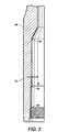
- upsets 12, 14 and 16 may include a spiral groove 24 in an outer circumferential surface for reducing differential pressure and sticking of the heavy weight drill pipe in the well bore.
- each upset includes a spiral groove 24 spirally 120° apart.
- the groove 24 is relatively shallow and substantially flat so that less than 4% of the middle of each upset is removed resulting in a negligible effect on the weight of the heavy weight drill pipe.
- dimension "D"in Figure 2 is about 0.56 cm (7/32 inch) for every 12.7 cm (5 inches) of outside diameter of the tubular member 10.
- the crucial material characteristics or properties of the tubular member 10 and first and second tool joints 20 and 22 are crucial to the durability and longevity of the heavy weight drill pipe in deviated or high angle well bores having a corrosive environment.
- the crucial material characteristics or properties typically include material hardness, yield strength and impact strength.
- the material hardness is preferably measured according to Brinell hardness (BHN) which is based on an outside surface test in the tubular member 10 however, may also be measured according to a Rockwell C hardness (HRC) based on laboratory test readings which represents hardness substantially throughout the entire tubular wall.
- the yield strength is typically measured by PSI and the impact strength is preferably measured in foot-pounds by a Charpy-V impact test conducted at ambient temperatures in the range of 21 °C - 23°C (70° -74°F.)
- tubular member 10 is treated to achieve at least substantially throughout the entire tubular member 10, a BHN of 217 to 241 for improved resistance to stress corrosion cracking and hydrogen embrittlement, a yield strength of 620,528 kPa (90,000 psi) to 723,949 kPa (105,000 psi) for improved resistance to bending stresses, and an impact strength of at least 136 J (100 ft.-lbs) at ambient temperatures for improved resistance to shock loads.
- each first and second tool joint 20 and 22 is specially treated to achieve at least substantially throughout the entirety of each first and second tool joint 20 and 22, a BHN of 258 for improved resistance to stress corrosion cracking and hydrogen embrittlement, a yield strength of 723,949 kPa (105,000 psi) for improved resistance to bending stresses, and an impact strength of at least 88 J (65 ft.-lbs) as measured by Charpy-V impact test at ambient temperatures for improved resistance to shock loads.
- Liquid quenching the tubular member 10 is a critical stage for achieving the unique combination of material properties described above because the fineness of the microstructure of the tubular member 10 is dependent upon the rate at which heat is removed. If heat is removed too slowly, the microstructure will be composed of undesirable pearlite and/or bainite. If the tubular member 10 is cooled too rapidly, the tubular member 10 may crack or even explode. Therefore, the quenching process must be fast enough to transform the microstructure to a phase commonly referred to as martensite without cracking the tubular member 10. This critical cooling rate must not only be achieved on the surface of the tubular member 10, but consistently throughout the material as well. Therefore, the tubular member 10 must have an adequate depth of hardening, which is the depth to which the rate of cooling is fast enough to transform the austenite to martensite.
- first and second tool joint 20 and 22 are treated in similar fashion to that described above in reference to the tubular member 10.
- each first and second tool joint 20 and 22 is first preheated to 924°C to 952°C (1695°F to 1745°F) to achieve an austenite phase or structure.
- the first and second tool joint 20 and 22 are then liquid quenched using water or any other suitable fluid for a period of 10 to 20 minutes, and then tempered to 688°C to 721°C (1270°F to 1330°F) for 30 to 45 minutes.
- the heavy weight drill pipe member is then tempered to 704°C (1300°F) for at least 20 minutes to achieve a preferred BHN of about 258, a yield strength of about 723,949 kPa (105,000 psi) and an impact strength of at least 88 J (65 ft.-lbs) at ambient temperatures throughout substantially the entire tubular member 10 and first and second tool join 20 and 22.
- first and second tool joint 20 and 22 may be permanently attached to a respective, first and second distal end 19 and 21 of the tubular member 10 and machined to form an externally threaded pin 23 on the first tool joint 20, and an internally threaded box 25 on the second tool joint 22 for connecting a respective heavy weight drill pipe member to the first and second tool joint 20 and 22.
Landscapes
- Engineering & Computer Science (AREA)
- Life Sciences & Earth Sciences (AREA)
- Geology (AREA)
- Mining & Mineral Resources (AREA)
- Mechanical Engineering (AREA)
- Physics & Mathematics (AREA)
- Environmental & Geological Engineering (AREA)
- Fluid Mechanics (AREA)
- General Life Sciences & Earth Sciences (AREA)
- Geochemistry & Mineralogy (AREA)
- Earth Drilling (AREA)
Claims (16)
- Elément de tige de forage à paroi épaisse approprié pour être utilisé dans un forage dévié ayant un environnement corrosif, comprenant :un corps tubulaire (10) ayant un alésage longitudinal (29) à travers celui-ci et une première (19) et une seconde (21) extrémité distale, au moins sensiblement tout le corps tubulaire ayant une dureté Brinell de 217 à 241 pour une résistance améliorée à la fissuration par corrosion sous tension et à la fragilisation par l'hydrogène, une limite d'élasticité de 620528 kPa à 723949 kPa (90000 psi à 105000 psi) pour une résistance améliorée aux contraintes de flexion, et une résistance à l'impact d'au moins 136 J (100 pieds - livre) telle que mesurée par un essai de résilience Charpy sur éprouvette avec entaille en V à températures ambiantes pour une résistance améliorée aux charges dynamiques,dans lequel l'élément de tige de forage à paroi épaisse peut être produit avec les étapes consistant à :préchauffer le corps tubulaire (10) ayant un alésage longitudinal (29) à travers celui-ci, et les première (19) et seconde (21) extrémités distales de 885°C à 913°C (1625°F à 1675°F) ;tremper en liquide le corps tubulaire (10) pendant 10 à 20 minutes ; etfaire revenir ledit corps tubulaire trempé pendant 20 à 40 minutes de 738°C à 766°C (1360°F à 1410°F) pour obtenir une dureté Brinell de 217 à 241, une limite d'élasticité de 620528 kPa à 723949 kPa (90000 psi à 105000 psi) et une résistance à l'impact d'au moins 136 J (100 pieds livre) sensiblement sur tout l'élément tubulaire.
- Elément de tige de forage à paroi épaisse selon la revendication 1, dans lequel au moins sensiblement tout le corps tubulaire a une dureté Brinell de 223 à 235, une limite d'élasticité de 655002 kPa à 689476 kPa (95000 psi à 100000 psi) et une résistance à l'impact d'au moins 136 J (100 pieds livre).
- Elément de tige de forage à paroi épaisse selon la revendication 1,
dans lequel au moins sensiblement tout le corps tubulaire a une dureté Brinell de 229, une limite d'élasticité de 655001 kPa (95000 psi) et une résistance à l'impact d'au moins 136 J (100 pieds livre). - Elément de tige de forage à paroi épaisse selon la revendication 1, comprenant en outre :un premier raccord de tige (20) et un second raccord de tige (22), lesdits premier et second raccords de tige étant raccordés à une première (19) et une seconde (21) extrémité distale respective du corps tubulaire (10) ;chacun desdits premier et second raccords de tige ayant une extrémité distale ouverte et un alésage longitudinal (27, 31) à travers en communication avec l'alésage longitudinal du corps tubulaire ;au moins sensiblement la totalité de chacun des premier et second raccords de tige ayant une dureté Brinell de 248 à 269 pour une résistance améliorée à la fissuration par corrosion sous contrainte et à la fragilisation par l'hydrogène, une limite d'élasticité de 689476 kPa à 792897 kPa (100000 psi à 115000 psi) pour une résistance améliorée aux contraintes de flexion et une résistance à l'impact d'au moins 88 J (65 pieds livre) telle que mesurée par un essai de résilience Charpy sur éprouvette avec entaille en V à températures ambiantes pour une résistance améliorée aux charges dynamiques.
- Elément de tige de forage à paroi épaisse selon la revendication 4, dans lequel au moins sensiblement la totalité de chacun des premier et second raccords de tige a une dureté Brinell de 254 à 263, une limite d'élasticité de 723949 kPa à 758423 kPa (105000 psi à 110000 psi) et une résistance à l'impact d'au moins 88 J (65 pieds livre).
- Elément de tige de forage à paroi épaisse selon la revendication 4, dans lequel au moins sensiblement la totalité de chacun des premier et second raccords de tige a une dureté Brinell de 258, une limite d'élasticité de 723949 kPa (105000 psi) et une résistance à l'impact d'au moins 88 J (65 pieds livre).
- Elément de tige de forage à paroi épaisse selon la revendication 4, dans lequel ledit premier raccord de tige a un axe (23) fileté à l'extérieur adjacent à l'extrémité distale ouverte pour raccorder par filetage un autre élément de tige de forage à paroi épaisse.
- Elément de tige de forage à paroi épaisse selon la revendication 4, dans lequel ledit second raccord de tige a une partie femelle filetée (25) intérieurement adjacente à l'extrémité distale ouverte pour raccorder par filetage un autre élément de tige de forage à paroi épaisse.
- Elément de tige de forage à paroi épaisse selon la revendication 8, dans lequel ladite partie femelle filetée (25) à l'intérieur comprend un alésage interne (31) s'étendant de manière axiale qui est constant sensiblement le long de l'axe longitudinal des filetages internes jusqu'à la seconde extrémité distale adjacente du corps tubulaire pour réduire la fatigue.
- Elément de tige de forage à paroi épaisse selon la revendication 1 , comprenant en outre :un ou plusieurs dispositifs de protection (12, 14, 16) positionnés le long de l'axe longitudinal du corps tubulaire, chacun desdits dispositifs de protection ayant un diamètre externe supérieur à un diamètre externe du corps tubulaire mais non supérieur à un diamètre externe de chacun des premier et second raccords de tige pour limiter les contraintes de flexion dans le corps tubulaire.
- Elément de tige de forage à paroi épaisse selon la revendication 10, dans lequel chacun desdits dispositifs de protection comprend une rainure en spirale (24) dans une surface circonférentielle externe pour réduire la pression différentielle et l'adhérence de la tige de forage à paroi épaisse dans le forage.
- Elément de tige de forage à paroi épaisse selon la revendication 11, dans lequel lesdites premier et second raccords de tige et au moins l'un desdits dispositifs de protection sont frettés sensiblement autour d'une surface circonférentielle externe (26, 28) pour réduire l'usure.
- Procédé permettant de produire un élément de tige de forage à paroi épaisse approprié pour être utilisé dans un forage dévié ayant un environnement corrosif, comprenant les étapes consistant à :préchauffer le corps tubulaire (10) ayant un alésage longitudinal (29) à travers celui-ci, et les première (19) et seconde (21) extrémités distales de 885°C à 913°C (1625°F à 1675°F) ;tremper en liquide le corps tubulaire (10) pendant 10 à 20 minutes ; etfaire revenir ledit corps tubulaire trempé pendant 20 à 40 minutes de 738°C à 766°C (1360°F à 1410°F) pour obtenir une dureté Brinell de 217 à 241, une limite d'élasticité de 620528 kPa à 723949 kPa (90000 psi à 105000 psi) et une résistance à l'impact d'au moins 136 J (100 pieds livre) sensiblement sur tout l'élément tubulaire.
- Procédé permettant de produire un élément de tige de forage à paroi épaisse selon la revendication 13, comprenant en outre les étapes consistant à :préchauffer un premier raccord de tige (20) et un second raccord de tige (22) de 924°C à 952°C (1695°F à 1745°F), chacun des premier et second raccords de tige ayant une extrémité distale ouverte et un alésage longitudinal (27, 31) à travers ceux-ci ;tremper en liquide lesdits premier et second raccords de tige pendant 10 à 20 minutes ;faire revenir lesdits premier et second raccords de tige trempés pendant 30 à 45 minutes de 688°C à 721 °C (1270°F à 1330°F) pour obtenir une dureté Brinell de 248 à 269, une limite d'élasticité de 689476 kPa à 792897 kPa (100000 psi à 115000 psi) et une résistance à l'impact d'au moins 88 J (65 pieds livre) sensiblement sur la totalité de chacun des premier et second raccords de tige ;fixer lesdits premier et second raccords de tige sur une première et une seconde extrémité distale respective de l'élément tubulaire.
- Procédé permettant de produire un élément de tige de forage à paroi épaisse selon la revendication 14, comprenant en outre l'étape consistant à usiner des filetages (23) sur un diamètre externe dudit premier raccord de tige adjacent à une extrémité distale ouverte pour raccorder un autre élément de tige de forage à paroi épaisse.
- Procédé permettant de produire un élément de tige de forage à paroi épaisse selon la revendication 14, comprenant en outre l'étape consistant à usiner des filetages (25) sur un diamètre interne dudit second raccord de tige adjacent à une extrémité distale ouverte pour raccorder un autre élément de tige de forage à paroi épaisse.
Applications Claiming Priority (3)
| Application Number | Priority Date | Filing Date | Title |
|---|---|---|---|
| US71253 | 1998-05-01 | ||
| US09/071,253 US6012744A (en) | 1998-05-01 | 1998-05-01 | Heavy weight drill pipe |
| PCT/US1999/009621 WO1999057478A1 (fr) | 1998-05-01 | 1999-04-30 | Tige de forage a parois epaisses |
Publications (3)
| Publication Number | Publication Date |
|---|---|
| EP1078190A1 EP1078190A1 (fr) | 2001-02-28 |
| EP1078190A4 EP1078190A4 (fr) | 2003-04-09 |
| EP1078190B1 true EP1078190B1 (fr) | 2006-07-12 |
Family
ID=22100205
Family Applications (1)
| Application Number | Title | Priority Date | Filing Date |
|---|---|---|---|
| EP99920274A Expired - Lifetime EP1078190B1 (fr) | 1998-05-01 | 1999-04-30 | Tige de forage a parois epaisses |
Country Status (9)
| Country | Link |
|---|---|
| US (1) | US6012744A (fr) |
| EP (1) | EP1078190B1 (fr) |
| JP (1) | JP2002513904A (fr) |
| CN (1) | CN1126894C (fr) |
| AR (1) | AR015061A1 (fr) |
| AU (1) | AU3781299A (fr) |
| CA (1) | CA2330963C (fr) |
| DE (1) | DE69932333T2 (fr) |
| WO (1) | WO1999057478A1 (fr) |
Families Citing this family (35)
| Publication number | Priority date | Publication date | Assignee | Title |
|---|---|---|---|---|
| GB0024909D0 (en) * | 2000-10-11 | 2000-11-22 | Springer Johann | Drill string member |
| WO2002088511A1 (fr) * | 2001-04-26 | 2002-11-07 | Furukawa Co., Ltd. | Tige tubulaire a etages et machine de forage |
| WO2002097232A1 (fr) * | 2001-06-01 | 2002-12-05 | Sandvik Tamrock Oy | Procede et dispositif de forage de roches, outil et trepan utilise pour le forage de roches |
| WO2004094768A2 (fr) * | 2003-04-23 | 2004-11-04 | Th Hill Associates, Inc. | Methodologie de conception de train de tiges permettant d'attenuer la rupture par fatigue |
| US7845434B2 (en) * | 2005-03-16 | 2010-12-07 | Troy Lee Clayton | Technique for drilling straight bore holes in the earth |
| US7472764B2 (en) * | 2005-03-25 | 2009-01-06 | Baker Hughes Incorporated | Rotary drill bit shank, rotary drill bits so equipped, and methods of manufacture |
| US7377137B1 (en) * | 2005-10-27 | 2008-05-27 | Bednarz James W | Barrel lock with infinite axial adjustment |
| US7377315B2 (en) * | 2005-11-29 | 2008-05-27 | Hall David R | Complaint covering of a downhole component |
| US20100018699A1 (en) * | 2007-03-21 | 2010-01-28 | Hall David R | Low Stress Threadform with a Non-conic Section Curve |
| US8201645B2 (en) * | 2007-03-21 | 2012-06-19 | Schlumberger Technology Corporation | Downhole tool string component that is protected from drilling stresses |
| US7497254B2 (en) * | 2007-03-21 | 2009-03-03 | Hall David R | Pocket for a downhole tool string component |
| US7669671B2 (en) | 2007-03-21 | 2010-03-02 | Hall David R | Segmented sleeve on a downhole tool string component |
| US20080302574A1 (en) * | 2007-06-08 | 2008-12-11 | Tt Technologies, Inc. | Drill stem and method |
| US20090025982A1 (en) * | 2007-07-26 | 2009-01-29 | Hall David R | Stabilizer Assembly |
| US7963323B2 (en) * | 2007-12-06 | 2011-06-21 | Schlumberger Technology Corporation | Technique and apparatus to deploy a cement plug in a well |
| US7814996B2 (en) * | 2008-02-01 | 2010-10-19 | Aquatic Company | Spiral ribbed aluminum drillpipe |
| US8002331B2 (en) | 2008-09-11 | 2011-08-23 | Honda Motor Company, Ltd. | Vehicles having utility dump bed and folding seat assembly |
| US8678447B2 (en) | 2009-06-04 | 2014-03-25 | National Oilwell Varco, L.P. | Drill pipe system |
| US8091627B2 (en) | 2009-11-23 | 2012-01-10 | Hall David R | Stress relief in a pocket of a downhole tool string component |
| CA3030731C (fr) | 2011-03-14 | 2021-04-20 | Rdt, Inc. | Tige de forage resistant a l'usure pour utilisation dans un environnement de fond de puits |
| US8955621B1 (en) | 2011-08-09 | 2015-02-17 | Turboflex, Inc. | Grooved drill string components and drilling methods |
| US9085942B2 (en) * | 2011-10-21 | 2015-07-21 | Weatherford Technology Holdings, Llc | Repaired wear and buckle resistant drill pipe and related methods |
| US9091124B2 (en) | 2011-10-21 | 2015-07-28 | Weatherford Technology Holdings, Llc | Wear and buckling resistant drill pipe |
| US9816328B2 (en) * | 2012-10-16 | 2017-11-14 | Smith International, Inc. | Friction welded heavy weight drill pipes |
| US9297410B2 (en) | 2012-12-31 | 2016-03-29 | Smith International, Inc. | Bearing assembly for a drilling tool |
| US9573432B2 (en) | 2013-10-01 | 2017-02-21 | Hendrickson Usa, L.L.C. | Leaf spring and method of manufacture thereof having sections with different levels of through hardness |
| RU2682281C2 (ru) * | 2013-10-25 | 2019-03-18 | НЭШНЛ ОЙЛВЕЛЛ ВАРКО, Эл.Пи. | Скважинные звенья очистки ствола и способ их применения |
| CN103711440A (zh) * | 2013-12-19 | 2014-04-09 | 江苏曙光华阳钻具有限公司 | 螺旋式加重钻杆 |
| US10815772B2 (en) | 2015-02-13 | 2020-10-27 | National Oilwell Varco, L.P. | Detection system for a wellsite and method of using same |
| US10648049B2 (en) * | 2015-04-14 | 2020-05-12 | Wellbore Integrity Solutions Llc | Heat treated heavy weight drill pipe |
| US9493993B1 (en) | 2015-06-10 | 2016-11-15 | Ptech Drilling Tubulars Llc | Work string and method of completing long lateral well bores |
| CN105041230A (zh) * | 2015-09-07 | 2015-11-11 | 山西风雷钻具有限公司 | 一种具有耐磨带的无磁承压钻杆 |
| US11473376B2 (en) * | 2018-03-16 | 2022-10-18 | Wwt North America Holdings, Inc | Non-rotating vibration reduction sub |
| USD954754S1 (en) * | 2020-02-28 | 2022-06-14 | Cobalt Extreme Pty Ltd | Rod coupler |
| CN112878925A (zh) * | 2021-01-29 | 2021-06-01 | 中国石油天然气集团有限公司 | 大水眼轻质修井钻杆 |
Citations (2)
| Publication number | Priority date | Publication date | Assignee | Title |
|---|---|---|---|---|
| US4226645A (en) * | 1979-01-08 | 1980-10-07 | Republic Steel Corp. | Steel well casing and method of production |
| US4354882A (en) * | 1981-05-08 | 1982-10-19 | Lone Star Steel Company | High performance tubulars for critical oil country applications and process for their preparation |
Family Cites Families (12)
| Publication number | Priority date | Publication date | Assignee | Title |
|---|---|---|---|---|
| AT308793B (de) * | 1968-12-02 | 1973-07-25 | Schoeller Bleckmann Stahlwerke | Austenitische Chrom-Nickel-Stickstoff-Stahllegierung für nichtmagnetisierbare Schwerstangen und Gestängeteile |
| US3784238A (en) * | 1971-05-17 | 1974-01-08 | Smith International | Intermediate drill stem |
| US3773359A (en) * | 1971-06-24 | 1973-11-20 | Smith International | Intermediate drill stem |
| US4273159A (en) * | 1978-03-16 | 1981-06-16 | Smith International, Inc. | Earth boring apparatus with multiple welds |
| US4416476A (en) * | 1980-09-17 | 1983-11-22 | Oncor Corporation | Intermediate weight drill stem member |
| US4460202A (en) * | 1980-11-26 | 1984-07-17 | Chance Glenn G | Intermediate weight drill string member |
| US4400349A (en) * | 1981-06-24 | 1983-08-23 | Sumitomo Metal Industries, Ltd. | Alloy for making high strength deep well casing and tubing having improved resistance to stress-corrosion cracking |
| JPS61130464A (ja) * | 1984-11-30 | 1986-06-18 | Nippon Steel Corp | 高耐食性高強度ドリルカラ−用非磁性鋼 |
| DE3445371A1 (de) * | 1984-12-10 | 1986-06-12 | Mannesmann AG, 4000 Düsseldorf | Verfahren zum herstellen von rohren fuer die erdoel- und erdgasindustrie und von bohrgestaengeeinheiten |
| IL82587A0 (en) * | 1986-05-27 | 1987-11-30 | Carpenter Technology Corp | Nickel-base alloy and method for preparation thereof |
| US4811800A (en) * | 1987-10-22 | 1989-03-14 | Homco International Inc. | Flexible drill string member especially for use in directional drilling |
| AT392802B (de) * | 1988-08-04 | 1991-06-25 | Schoeller Bleckmann Stahlwerke | Verfahren zur herstellung von spannungsrisskorrosionsbestaendigen rohrfoermigen koerpern, insbesondere nichtmagnetisierbaren schwerstangen aus austenitischen staehlen |
-
1998
- 1998-05-01 US US09/071,253 patent/US6012744A/en not_active Expired - Lifetime
-
1999
- 1999-04-30 CN CN99808148A patent/CN1126894C/zh not_active Expired - Lifetime
- 1999-04-30 EP EP99920274A patent/EP1078190B1/fr not_active Expired - Lifetime
- 1999-04-30 WO PCT/US1999/009621 patent/WO1999057478A1/fr active IP Right Grant
- 1999-04-30 CA CA002330963A patent/CA2330963C/fr not_active Expired - Lifetime
- 1999-04-30 JP JP2000547400A patent/JP2002513904A/ja active Pending
- 1999-04-30 DE DE69932333T patent/DE69932333T2/de not_active Expired - Lifetime
- 1999-04-30 AU AU37812/99A patent/AU3781299A/en not_active Abandoned
- 1999-05-03 AR ARP990102061A patent/AR015061A1/es active IP Right Grant
Patent Citations (2)
| Publication number | Priority date | Publication date | Assignee | Title |
|---|---|---|---|---|
| US4226645A (en) * | 1979-01-08 | 1980-10-07 | Republic Steel Corp. | Steel well casing and method of production |
| US4354882A (en) * | 1981-05-08 | 1982-10-19 | Lone Star Steel Company | High performance tubulars for critical oil country applications and process for their preparation |
Also Published As
| Publication number | Publication date |
|---|---|
| EP1078190A4 (fr) | 2003-04-09 |
| CA2330963A1 (fr) | 1999-11-11 |
| DE69932333D1 (de) | 2006-08-24 |
| CN1308715A (zh) | 2001-08-15 |
| US6012744A (en) | 2000-01-11 |
| WO1999057478A1 (fr) | 1999-11-11 |
| DE69932333T2 (de) | 2007-07-19 |
| AR015061A1 (es) | 2001-04-11 |
| JP2002513904A (ja) | 2002-05-14 |
| CN1126894C (zh) | 2003-11-05 |
| AU3781299A (en) | 1999-11-23 |
| EP1078190A1 (fr) | 2001-02-28 |
| CA2330963C (fr) | 2008-06-17 |
Similar Documents
| Publication | Publication Date | Title |
|---|---|---|
| EP1078190B1 (fr) | Tige de forage a parois epaisses | |
| US4710245A (en) | Method of making tubular units for the oil and gas industry | |
| EP2028403B1 (fr) | Joint fileté doté de charges radiales élevées et de surfaces traitées différentiellement | |
| EP1259655B1 (fr) | Element allonge et acier pour forage de roches par percussion | |
| CA2682959A1 (fr) | Tube d'acier sans soudure utilise comme section verticale de reconditionnement | |
| US20060289074A1 (en) | Pipe with a canal in the pipe wall | |
| CN101581200A (zh) | 一种120钢级钻杆及其制造工艺方法 | |
| US20070068607A1 (en) | Method for heat treating thick-walled forgings | |
| JP2008534822A (ja) | 径方向拡張システム | |
| CA2254760A1 (fr) | Tige de forage soudee par friction et procede de fabrication d'une telle tige | |
| US10648049B2 (en) | Heat treated heavy weight drill pipe | |
| US5334268A (en) | Method of producing high strength sucker rod coupling | |
| US11408234B2 (en) | Landing pipe | |
| CA2257488A1 (fr) | Tige de forage soudee par friction et procede de fabrication de cette tige | |
| US5988301A (en) | Drill rod and method for its manufacture | |
| Garrison et al. | Production and fit for service attributes of C125 high strength casing | |
| US20210025248A1 (en) | Centralizer | |
| WO2003062484A1 (fr) | Element pour forage de roches par percussion et son procede de production | |
| Urband et al. | The effects of OCTG connection swaging and stress relieving on SSC resistance | |
| RU14995U1 (ru) | Соединение насосно-компрессорных или бурильных труб | |
| Tsukano et al. | Development of sour service drillstring with 110-ksi yield strength | |
| JPS6256525A (ja) | サツカ−ロツド等用のカツプリングの製造方法 | |
| Bybee | Drillstring Technology for World-Class Extended-Reach Drilling | |
| EP2754851B1 (fr) | Tuyau de forage amélioré | |
| Linne et al. | Drill pipes for Sour Service |
Legal Events
| Date | Code | Title | Description |
|---|---|---|---|
| PUAI | Public reference made under article 153(3) epc to a published international application that has entered the european phase |
Free format text: ORIGINAL CODE: 0009012 |
|
| 17P | Request for examination filed |
Effective date: 20001114 |
|
| AK | Designated contracting states |
Kind code of ref document: A1 Designated state(s): DE FR GB IT |
|
| A4 | Supplementary search report drawn up and despatched |
Effective date: 20030221 |
|
| RIC1 | Information provided on ipc code assigned before grant |
Ipc: 7C 21D 9/00 B Ipc: 7C 22C 38/00 B Ipc: 7E 21B 17/16 B Ipc: 7F 16L 25/00 A |
|
| 17Q | First examination report despatched |
Effective date: 20040702 |
|
| GRAP | Despatch of communication of intention to grant a patent |
Free format text: ORIGINAL CODE: EPIDOSNIGR1 |
|
| GRAS | Grant fee paid |
Free format text: ORIGINAL CODE: EPIDOSNIGR3 |
|
| GRAA | (expected) grant |
Free format text: ORIGINAL CODE: 0009210 |
|
| AK | Designated contracting states |
Kind code of ref document: B1 Designated state(s): DE FR GB IT |
|
| PG25 | Lapsed in a contracting state [announced via postgrant information from national office to epo] |
Ref country code: IT Free format text: LAPSE BECAUSE OF FAILURE TO SUBMIT A TRANSLATION OF THE DESCRIPTION OR TO PAY THE FEE WITHIN THE PRESCRIBED TIME-LIMIT;WARNING: LAPSES OF ITALIAN PATENTS WITH EFFECTIVE DATE BEFORE 2007 MAY HAVE OCCURRED AT ANY TIME BEFORE 2007. THE CORRECT EFFECTIVE DATE MAY BE DIFFERENT FROM THE ONE RECORDED. Effective date: 20060712 |
|
| REG | Reference to a national code |
Ref country code: GB Ref legal event code: FG4D |
|
| REF | Corresponds to: |
Ref document number: 69932333 Country of ref document: DE Date of ref document: 20060824 Kind code of ref document: P |
|
| ET | Fr: translation filed | ||
| PLBE | No opposition filed within time limit |
Free format text: ORIGINAL CODE: 0009261 |
|
| STAA | Information on the status of an ep patent application or granted ep patent |
Free format text: STATUS: NO OPPOSITION FILED WITHIN TIME LIMIT |
|
| 26N | No opposition filed |
Effective date: 20070413 |
|
| REG | Reference to a national code |
Ref country code: FR Ref legal event code: PLFP Year of fee payment: 18 |
|
| REG | Reference to a national code |
Ref country code: FR Ref legal event code: PLFP Year of fee payment: 19 |
|
| REG | Reference to a national code |
Ref country code: FR Ref legal event code: PLFP Year of fee payment: 20 |
|
| PGFP | Annual fee paid to national office [announced via postgrant information from national office to epo] |
Ref country code: GB Payment date: 20180329 Year of fee payment: 20 |
|
| PGFP | Annual fee paid to national office [announced via postgrant information from national office to epo] |
Ref country code: FR Payment date: 20180315 Year of fee payment: 20 |
|
| PGFP | Annual fee paid to national office [announced via postgrant information from national office to epo] |
Ref country code: DE Payment date: 20180417 Year of fee payment: 20 |
|
| PGFP | Annual fee paid to national office [announced via postgrant information from national office to epo] |
Ref country code: IT Payment date: 20180420 Year of fee payment: 20 |
|
| REG | Reference to a national code |
Ref country code: DE Ref legal event code: R071 Ref document number: 69932333 Country of ref document: DE |
|
| REG | Reference to a national code |
Ref country code: GB Ref legal event code: PE20 Expiry date: 20190429 |
|
| PG25 | Lapsed in a contracting state [announced via postgrant information from national office to epo] |
Ref country code: GB Free format text: LAPSE BECAUSE OF EXPIRATION OF PROTECTION Effective date: 20190429 |