EP1077734B1 - Volume control apparatus for a flexible venous reservoir - Google Patents
Volume control apparatus for a flexible venous reservoir Download PDFInfo
- Publication number
- EP1077734B1 EP1077734B1 EP99921422A EP99921422A EP1077734B1 EP 1077734 B1 EP1077734 B1 EP 1077734B1 EP 99921422 A EP99921422 A EP 99921422A EP 99921422 A EP99921422 A EP 99921422A EP 1077734 B1 EP1077734 B1 EP 1077734B1
- Authority
- EP
- European Patent Office
- Prior art keywords
- pressure plate
- arm
- panel
- storage chamber
- blood storage
- Prior art date
- Legal status (The legal status is an assumption and is not a legal conclusion. Google has not performed a legal analysis and makes no representation as to the accuracy of the status listed.)
- Expired - Lifetime
Links
- 239000008280 blood Substances 0.000 claims description 73
- 210000004369 blood Anatomy 0.000 claims description 73
- 230000017531 blood circulation Effects 0.000 claims description 22
- 230000001276 controlling effect Effects 0.000 claims description 19
- 230000001105 regulatory effect Effects 0.000 claims description 13
- 238000013022 venting Methods 0.000 claims description 3
- 239000012780 transparent material Substances 0.000 claims description 2
- 239000000463 material Substances 0.000 description 6
- 238000010276 construction Methods 0.000 description 5
- 238000000034 method Methods 0.000 description 3
- 239000007787 solid Substances 0.000 description 3
- 230000004087 circulation Effects 0.000 description 2
- 230000000295 complement effect Effects 0.000 description 2
- 210000005069 ears Anatomy 0.000 description 2
- 230000007246 mechanism Effects 0.000 description 2
- 230000002411 adverse Effects 0.000 description 1
- 238000007675 cardiac surgery Methods 0.000 description 1
- 230000002612 cardiopulmonary effect Effects 0.000 description 1
- 238000013130 cardiovascular surgery Methods 0.000 description 1
- 238000001914 filtration Methods 0.000 description 1
- 210000004072 lung Anatomy 0.000 description 1
- 238000006213 oxygenation reaction Methods 0.000 description 1
- 230000037452 priming Effects 0.000 description 1
- 239000000126 substance Substances 0.000 description 1
- 238000011144 upstream manufacturing Methods 0.000 description 1
Images


Classifications
-
- A—HUMAN NECESSITIES
- A61—MEDICAL OR VETERINARY SCIENCE; HYGIENE
- A61M—DEVICES FOR INTRODUCING MEDIA INTO, OR ONTO, THE BODY; DEVICES FOR TRANSDUCING BODY MEDIA OR FOR TAKING MEDIA FROM THE BODY; DEVICES FOR PRODUCING OR ENDING SLEEP OR STUPOR
- A61M1/00—Suction or pumping devices for medical purposes; Devices for carrying-off, for treatment of, or for carrying-over, body-liquids; Drainage systems
- A61M1/36—Other treatment of blood in a by-pass of the natural circulatory system, e.g. temperature adaptation, irradiation ; Extra-corporeal blood circuits
- A61M1/3621—Extra-corporeal blood circuits
- A61M1/3627—Degassing devices; Buffer reservoirs; Drip chambers; Blood filters
-
- A—HUMAN NECESSITIES
- A61—MEDICAL OR VETERINARY SCIENCE; HYGIENE
- A61M—DEVICES FOR INTRODUCING MEDIA INTO, OR ONTO, THE BODY; DEVICES FOR TRANSDUCING BODY MEDIA OR FOR TAKING MEDIA FROM THE BODY; DEVICES FOR PRODUCING OR ENDING SLEEP OR STUPOR
- A61M2205/00—General characteristics of the apparatus
- A61M2205/33—Controlling, regulating or measuring
- A61M2205/3379—Masses, volumes, levels of fluids in reservoirs, flow rates
Definitions
- the invention relates generally to the practice of cardiac surgery, and more specifically to an apparatus for managing venous blood being returned from the body and/or from a cardiotomy device.
- Such extracorporeal arrangements typically include a reservoir, typically called a venous reservoir, to store a certain volume of blood. Often, the reservoir receives blood from the main attachment to the venous circulation, and "cardiotomy" blood collected by suction from the surgical site.
- the venous reservoir provides a volume buffer for the extracorporeal system, and also a measure of air bubble removal.
- venous reservoirs with rigid walls, and also to provide venous reservoirs which have flexible walls.
- Flexible venous reservoirs constructed in the form of a bag or pouch of flexible, polymeric material have the advantage of providing a smooth, even flow of blood from an inlet to an outlet. This is useful since blood is a fragile substance, and likely to be adversely affected if allowed to lie stagnant in any portion of the extracorporeal circuit.
- Flexible venous reservoirs typically have one or more vents at the top to allow the venting off of gas bubbles which have entered the blood upstream of the reservoir (e.g., in the cardiotomy blood).
- Document US-A-5 720 741 describes a combination of a flexible venous reservoir and a volume controlling apparatus as defined in the preamble of claim 1.
- the front plate covers substantially the entire front and back surface of the flexible reservoir, leaving no access to the reservoir for manipulation to expedite air bubble removal without releasing the entire reservoir from restraint.
- US Patent No. 5,573,526 discloses another flexible reservoir and a volume restricting holder assembly comprising a rigid base plate and a volume restriction plate, which define a V-shaped gap of variable size for receiving the flexible reservoir.
- the invention provides a volume controlling support for a flexible venous reservoir that permits the reservoir to have a clear flow passage from its inlet to its outlet which is visible and accessible to the perfusionist.
- the portion of the reservoir through which the major part of the blood flow is occurring can be manipulated if necessary, particularly for the purpose of manipulating the reservoir to improve the clearance of air bubbles in the blood.
- Preferred embodiments also enhance the convenience for the perfusionist by permitting right-handed or left-handed operation, by providing an approximate read-out of the volume of blood contained in the reservoir, and/or by permitting operation with different size flexible venous reservoirs.
- a first aspect of the invention as defined in claim 1 is a combination of a flexible venous reservoir and a volume controlling apparatus.
- the flexible reservoir comprises flexible walls defining a blood storage chamber having an upper perimeter, and an inlet and an outlet to the blood storage chamber defining a blood flow path through the blood storage chamber between the inlet and outlet.
- the volume controlling apparatus comprises a panel, a pressure plate, and adjustable mounting means for movably mounting the pressure plate on the panel so that the flexible venous reservoir can be positioned between the panel and the pressure plate and in contact with both to adjustably limit the maximum volume of the flexible venous reservoir.
- the pressure plate is sized relative to the blood storage chamber such that a significant blood flow passage remains uncovered by the pressure plate along the upper perimeter of the blood storage chamber from the inlet to the outlet.
- the adjustable mounting means comprises a cross arm having one end connected to the pressure plate, and a position regulating apparatus for moving the cross arm relative to the panel and holding the cross arm in position.
- the position regulating apparatus comprises first and second arms, and a lead screw.
- the first and second arms are pivotably connected together at one end of each of the first and second arms, with the first arm being mounted to the panel and the second arm being mounted to the cross arm.
- the lead screw engages the first and second arms to pivot the second arm relative to the first arm as the lead screw is turned to move the cross arm and pressure plate relative to the panel.
- the position regulating apparatus further includes a knob connected to the lead screw for manually turning the lead screw, and a dial indicator connected to the lead screw so that the dial indicator rotates as the lead screw is turned.
- the dial indicator is marked with indicia corresponding to the approximate maximum volume permitted in the flexible venous reservoir for various positions of the pressure plate relative to the panel.
- the lead screw engages the second arm via a trunion that is pivotably mounted to the second arm so that the trunion maintains a constant orientation relative to the first arm as the lead screw is turned.
- the dial indicator is mounted to the trunion so that the dial indicator maintains a constant orientation relative to the first arm and panel as the second arm pivots relative to the first arm.
- the first arm comprises a mounting frame mountable in fixed relationship with the panel.
- the mounting frame includes two hub portions each having a through opening.
- the second arm constitutes a lever having first and second ends.
- the position regulating apparatus further comprises an axle through the lever and the through openings of the mounting frame to pivotably mount the first end of the lever on the mounting frame.
- the cross arm is connected to the second end of the lever, and the trunion is mounted in the lever intermediate the first and second ends thereof.
- a dial frame is provided for the indicator dial and a key-and-slot connection is provided between dial frame and trunion to mount the indicator dial on the trunion.
- the position regulating apparatus further includes stops that limit the range of motion of the second arm relative to the first arm, and the dial indicator rotates through no more than one full rotation throughout the range of motion of the second arm relative to the first arm.
- the pressure plate is free to articulate relative to the cross arm to allow the pressure plate to self-level relative to the venous reservoir.
- the pressure plate may be mounted to the cross arm by a ball-and-socket joint.
- a vent passageway is provided into the blood storage chamber generally adjacent the upper perimeter of the blood storage chamber for venting air bubbles from the blood storage chamber.
- the pressure plate is preferably generally flat and has a generally circular configuration to define the blood flow passage as generally arcuate.
- one side of the blood storage chamber is substantially covered by the pressure plate other than the blood flow passage along the upper periphery of the blood storage chamber, and the panel substantially covers the other side of the blood storage chamber at least other than the blood flow passage. It is most preferred for the panel to cover the entire back side of the blood storage chamber.
- the pressure plate is formed of transparent material to allow the perfusionist to view the portion of the blood storage chamber covered by the pressure plate.
- the flexible venous reservoir and pressure plate constitute a first flexible venous reservoir and a first pressure plate, respectively.
- the combination further comprises a second flexible venous reservoir forming a different size blood storage chamber than the blood storage chamber of the first flexible venous reservoir, and a second pressure plate of different size than the first pressure plate to correspond to the size of the blood storage chamber of the second flexible venous reservoir.
- the first and second pressure plates are preferably interchangeably mountable by the adjustable mounting means.
- the volume controlling apparatus of the second aspect of the invention generally comprises a panel, a pressure plate, and adjustable mounting means for movably mounting the pressure plate on the panel so that the flexible venous reservoir can be positioned between the panel and the pressure plate and in contact with both to adjustably limit the maximum volume of the flexible venous reservoir.
- the pressure plate is free to articulate relative to the adjustable mounting means to allow the pressure plate to self-level with respect to the flexible venous reservoir.
- a volume controlling apparatus comprising a panel having opposite side edges, a pressure plate, and adjustable mounting means, attachable to the panel adjacent either side edge of the panel, for movably mounting the pressure plate on the panel so that the flexible venous reservoir can be positioned between the panel and the pressure plate and in contact with both to adjustably limit the maximum volume of the flexible venous reservoir.
- the adjustable mounting means comprises a cross arm having one end connected to the pressure plate, and a position regulating apparatus for moving the cross arm relative to the panel and holding the cross arm in position.
- the panel has a front side and the direction between the opposite side edges of the panel constitutes a lateral direction.
- the cross arm is pivotable generally laterally between an operating position wherein the pressure plate is held in front of the front side of the panel, and a loading position wherein the pressure plate is pivoted to a position generally laterally away from front side of the panel.
- the operating position and loading position of the cross arm are reversed when the adjustable mounting means is switched between being mounted adjacent one side edge of the panel to the other side edge of the panel.
- a volume controlling apparatus generally comprising a panel, a pressure plate, and adjustable mounting means for movably mounting the pressure plate on the panel so that the flexible venous reservoir can be positioned between the panel and the pressure plate and in contact with both to adjustably limit the maximum volume of the flexible venous reservoir.
- a dial indicator is operatively connected to the adjustable mounting means so that the dial indicator rotates as the pressure plate is moved relative to the panel.
- the dial indicator is marked with indicia corresponding to the approximate maximum volume permitted in the flexible venous reservoir for various positions of the pressure plate relative to the panel.
- dial indicator is operatively connected to the adjustable mounting means via a cable linkage.
- a suitable drive means may also be provided for driving the cable linkage to drive the adjustable mounting means to move the pressure plate relative to the panel.
- the dial indicator includes indicia along at least two scales corresponding to at least two flexible venous reservoirs having blood storage chambers of different sizes.
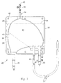
- a front plan view of a flexible venous reservoir 20 is illustrated.
- the body 22 of the flexible venous reservoir 20 is conveniently fabricated from two sheets of flexible, substantially transparent, polymeric material forming a first (front in this view) wall 24 and a second (rear in this view) wall 26, the first and second walls being heat sealed in a region 28 adjacent to their edges to form a bag-like construction.
- the flexible venous reservoir 20 is provided with two inlets 30 and 32, one to serve to inlet blood coming directly from the patient's circulation, and the other to serve to inlet cardiotomy blood.
- An outlet 34 is provided to conduct the blood to the next stage of processing.
- a specialized air vent 36 is provided at the top of the flexible venous reservoir 20 so that the air from bubbles that have separated from blood can be purged.
- the vent 36 conveniently includes a valve 38 and a luer connection 40.
- the flexible venous reservoir 20 defines an internal blood storage chamber 21 formed by sheets of polymeric material and heat seals.
- the upper perimeter 23 of the blood storage chamber 21 is preferably generally arcuate to define a generally arcuate blood flow path or passage through the blood storage chamber 21 between the inlets 30,32 and outlet 34.
- the vent 36 preferably communicates with the top of the arc of the blood storage chamber21, as illustrated in figure 1.
- a series of holes 42 within the heat-sealed region 28 may conveniently be used to support the reservoir 20.
- a screen 43 formed of a fine mesh of polymeric material and disposed within the bag-like construction flexible venous reservoir 20, receives the blood entering through both inlets 30 and 34. Under most operating conditions, all of the blood must pass through the screen 43 to reach the outlet 34, but the upper margin 44 of the screen is left open as a bypass route for the blood to the outlet in unusual conditions.
- the support 60 includes a panel 62 which serves as a backstop against which the flexible venous reservoir 20 can be compressed.
- the panel 62 is conveniently attached to a mounting arm 64 which includes first arm section 66 having a mounting clamp 68, and a second arm section 70 attached to panel 62.
- the mounting clamp 68 can be tightened onto a pole or other stand in the operating theater by turning clamp tightening knob 72, and the angular relation between first arm section 66 and second arm section 70 can be adjusted by turning arm tightening knob 74.
- a series of pins 76, each having a circumferential groove 78 are attached to panel 62, positioned so that the pins 76 can enter the holes 42 in the reservoir 20, with the reservoir hanging in the grooves.
- Other expedients, such as spring loaded clips, will suggest themselves to the artisan for securing the reservoir 20 to the panel 62.
- An inlet clamp 80 is preferably provided, which is sized and shaped to receive the inlets 30 and 32, conveniently with a snap fit.
- a vent clamp 82 is preferably provided to receive the reservoir's vent 36, and an outlet clamp 84 (seen in Figs. 4 and 5) is preferably provided to receive the reservoir's outlet 34.
- the panel 62 has a front side (the reservoir side in Figs. 2, 4a, 4b and 5), and the direction between the opposite side edges 65 and 67 of the panel 62 constitutes a lateral direction (e.g., rightwardly or leftwardly away from the panel in Figs. 4a and 4b).
- the directions perpendicular to the plane of the panel 62 constitute either the forward or rearward direction, it being understood that the direction upwardly out of the page of Figs. 4a and 4b constitutes the forward direction.
- the panel 62 preferably includes a flat transparent window 63 that supports the back side of the flexible venous reservoir.
- the panel may alternatively be formed by any suitable support structure, such a grill, grid or mesh, solid opaque or translucent surface, etc.
- a volume limit assembly 90 acts to limit the maximum volume the flexible venous reservoir 20 can contain.
- the volume limit assembly 90 includes a mounting frame 92 which as a pair of grooves 94 and 96; each of these grooves is sized to receive panel 62 within itself so that the volume limit assembly 90 can be clamped to the left or to the right edge of panel 62.
- the mounting frame 92 is depicted clamped to the left edge of panel 62, with the panel 62 in groove 94.
- the volume controlling support can thus easily be set up for right-handed or left-handed operation depending on the preference of the perfusionist.
- the mounting frame 92 is pivotally mounted at a pivot joint 98 to a lever 100.
- the lever 100 is pivotally attached at its other end to a cross arm 102 at pivot 104.
- the mounting frame 92 constitutes a preferred embodiment of a first arm (also 92), and the lever 100 constitute a preferred embodiment of a second arm (also 100). It will be appreciated that the first and second arms 92 and 100 could be modified so that the first arm 92 pivots relative to the panel 62, and the second arm either also pivots or is connected so as to merely move outwardly with little or no pivotable motion of the second arm relative to the panel.
- motion such as pivoting
- one member relative to another means that either member can be viewed as stationary outside the system comprising the two members so long as one of the members moves relative to the other.
- the cross arm 102 is preferably attached to a pressure plate 106 in such a manner as to allow the pressure plate 106 to articulate, conveniently by a ball-and-socket joint 108, thus permitting the pressure plate 106 to beself-leveling against the flexible venous reservoir 20.
- the ball-and-socket joint 108 has a resilient socket so that the pressure plate 106 can be rapidly replaced with another of a different size or shape to accommodate alternative flexible venous reservoirs 20.
- Alternative means for connecting the pressure plate 106 to the cross arm 102 to allow articulation of the pressure plate 106 include, for example, a universal joint, flexible rubber connection, etc.
- At least two sizes of flexible venous reservoirs 20 and pressure plates 106 are provided. These include a second flexible venous reservoir forming a different size blood storage chamber than the blood storage chamber 21 of the first flexible venous reservoir 20, and a second pressure plate of different size than the first pressure plate 106 to correspond to the size of the blood storage chamber of the second flexible venous reservoir.
- the first and second reservoirs and pressure plates may otherwise be of the same design, although it is contemplated that they could otherwise have different configurations, be formed of different materials or constructions.
- the ball-and-socket joint 108 or other suitable mounting means in this embodiment would releasably hold the pressure plate 106 on the cross arm 102 to permit interchanging the first and second pressure plates. Additional types of sizes of pressure plates could also be provided.
- the pressure plate 106 is generally flat, circular and is formed of transparent polymeric material.
- the pressure plate may be formed in other configurations, and may comprise a grill, grid or mesh, solid opaque plate or other construction, although these are not preferred.
- the preferred circular configuration of the pressure plate 106 and the preferred size of the pressure plate 106 help define the blood flow passage through the blood storage chamber 21 of the venous reservoir 20 as generally arcuate between the circular periphery of the pressure plate 106 and the generally arcuate upper periphery of the blood storage chamber 21. This provides access to this part of the venous reservoir 20, as well as providing this arcuate flow channel or passage when the pressure plate 106 is moved to a position closest to the panel 62 as permitted by the stop bar 118.
- the gap between the pressure plate 106 and the panel 62 is very narrow at this position (which may be referred to as a "closed position" notwithstanding the fact that the blood flow channel or passage is open and the fact that blood flow is preferably not completely closed off through the blood storage chamber 21 behind the pressure plate 106).
- the blood flow channel or passage between the periphery of the pressure plate 106 and the upper periphery 23 of the blood storage chamber 21 may have a greater cross sectional area generally adjacent the vent 36 so that blood tends to decelerate adjacent the vent 36 to assist in allowing any air emboli entrained in the blood flow to travel upwardly to the vent 36.
- pressure plate 106 in its closed position and the arcuate blood flow passage can be employed to facilitate in the priming or draining of the blood storage chamber 21.
- one side of the blood storage chamber 21 is substantially covered by the pressure plate 106 other than the blood flow passage along the upper periphery of the blood storage chamber, and the panel 62 substantially covering the other side of the blood storage chamber 21, at least other than the blood flow passage.
- the transparent window 63 of the preferred embodiment of the panel 62 completely covers the "back" side of the blood storage chamber 21 of the venous reservoir 20.
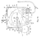
- the position of lever 100 around pivot joint 98 can be adjusted by turning volume control knob 110.
- Turning volume control knob 110 rotates lead screw 112, which interacts with a pivoting trunion 114 in lever 100, and with threaded fitting 116 within the frame 92 (which may also be a pivotable trunion).
- the lead screw 112, and conveniently its volume control knob 110 constitute an operative part of a preferred embodiment of a position regulating apparatus 117.
- the maximum travel of lead screw 112 is limited at one end by stop bar 118, and at the other end by screw stop 120.
- the stop bar 118 defines the limit to the range of motion of the pressure plate 106 that is referred to as the "closed" position
- the screw stop 120 defines the limit of the range of motion of the pressure plate that is referred to as the "open” position.
- the open position is sufficiently open to permit the cross arm 102 to be pivoted laterally from its operating position (solid in Fig. 4b) to its loading position (phantom in Fig. 4b) even when the venous reservoir is full.
- the "closed" position does not completely close the covered portion of the blood storage chamber to blood flow.
- a dial indicator 122 has teeth at its periphery 123 which intermesh with teeth on a pinion gear 124 on lead screw 112 such that the dial indicator rotates in proportion to the rotation of the lead screw 112, calibrated to provide an approximate read-out of the maximum volume which that positioning of the cross arm 102 and pressure plate 106 permits within the flexible venous reservoir 20.
- the gear ratio between the pinion gear 124 and the dial indicator 122 is such that the full range of motion of the lead screw 112, cross arm 102 and pressure plate 106 causes less than a full rotation of the dial indicator 122, most preferably just slightly less than full rotation.
- the lead screw may advance one inch (25.4mm) over four rotations, and the gear ratio (teeth ratio) between the pinion gear 124 and the dial indicator may be approximately 13:93. The range of motion can then be set to provide less than one full rotation of the dial indicator 122.
- Dial indicator 122 is provided with indicia which are read in reference to pointer 125.
- the indicia may indicated several scales which are calibrated to different sizes and models of flexible venous reservoirs 20.
- two scales may be provided as illustrated in Fig. 6.
- the dial indicator 122 may also be considered as a portion of position regulating apparatus 117.
- the dial indicator 122 is believed to provide a high degree of resolution within a relatively small area. This is because the indicia are provided circumferentially along the dial indicator 122, resulting in indicia along an circle having a circumference equal to ⁇ times the diameter of the indicia. A longitudinal volume indicator, in contrast, would require a length more than three times longer than the diameter of the indicia to provide the same amount of resolution.
- the cross arm 102 is preferably pivotable generally laterally between an operating position (solid lines in Figs. 4a and 4b) and a loading position (phantom lines in Fig. 4b).
- the pressure plate 106 In the operating position, the pressure plate 106 is held in front of the front side of the panel 62 to restrain the flexible venous reservoir 20 between the pressure plate 106 and panel 62.
- the loading position the pressure plate 106 is pivoted to a position generally laterally away from front side of the panel 62 to load or unload the flexible venous reservoir 20 or otherwise obtain greater access to the flexible venous reservoir 20.
- the operating position and loading position of the cross arm 106 are reversed when the adjustable mounting means is switched between being mounted adjacent one side edge of the panel 62 (e.g., the left side edge in figure 4) to the other side edge of the panel 62 (e.g., the right side edge).
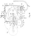
- FIG. 3 a detail perspective view of the volume limit assembly 90 of the volume controlling support 60 is illustrated.
- a rotation stop 128 can be appreciated, which stop interacts with projecting ears 130 and 132.
- the cross-arm 102 can pivot from a first position defined by the contact with rotation stop 128 and projecting ear 130 for left-handed operation when the volume limit assembly is attached to the left side of panel 62 (the position illustrated in solid lines in Fig. 4b), to a second position defined by the contact with rotation stop 128 and projecting ear 132 for right-handed operation when the volume limit assembly is attached to the right side of panel 62.
- This arrangement conveniently allows the pressure plate 106 to be rotated completely out of the way of the flexible venous reservoir 20 (as illustrated in phantom in Fig. 4b) if for any reason the perfusionist wishes complete access to the reservoir.
- Fig. 4 is a perspective view of the volume controlling support 60 with a flexible venous reservoir 20 in place is illustrated.
- the pressure plate 106 is shaped and sized so that a significant flow passage (depicted by the sequence of arrows 140) exists within the flexible venous reservoir 20 from the inlet 30 to the outlet 34 adjacent to portions of the flexible venous reservoir which are not covered by the pressure plate.
- the phrase "significant flow passage” means that the flow passage is sufficient to allow various flow rates that would be expected during cardiopulmonary bypass. This also allows the flexible venous reservoir 20 to be inspected and manipulated to enhance the clearance of air bubbles from the blood contained in the flexible venous reservoir without releasing the reservoir from the volume limiting restraint provided by the pressure plate 106.
- rotation stop 128a is positioned on the cross arm 102, and projecting ears 130a and 132a are provided on lever 100. Any other suitable methods or structures that provide rotational limits may also be employed.
- adjustable mounting means for movably mounting the pressure plate on the panel so that the flexible venous reservoir can be positioned between the panel and the pressure plate and in contact with both to adjustably limit the maximum volume of the flexible venous reservoir
- adjustable mounting means includes the preferred embodiment for accomplishing this function, e.g., the cross arm 102, lead screw 112, frame 92, lever 100 and knob 110, as well as any other way to accomplishing this function.
- adjustable mounting means is also intended to cover the types of mechanisms disclosed in US Patent Nos. 5,352,218; 5,573,526; 5,693,039 and 5,720,741.
- any suitable means for mounting an assembly on along either side edge of a panel may be employed, for example, threaded fasteners, snap connections, magnetic means (possibly in combination with other means), overcenter locking or clamping mechanisms (such as provided by vices that would either clamp the adjustable mounting means to the panel or the panel to the adjustable mounting means) or any combination of such means.
- the adjustable mounting means is releasably"attachable to the panel adjacent either side edge of the panel"by the pair of grooves 94 and 96 that alternatively receive the panel 62 depending upon whether the frame 92 is being mounted on the left or right side edge of the panel 62, and the frame 92 is clamped to the panel 62.
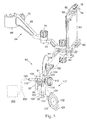
- FIG. 5 an exploded view of the volume controlling support 60 is illustrated.
- one or more thumbscrews 150 can be provided to conveniently attach the volume limit assembly 90 to the panel 62.
- the trunion 114 may have projecting tabs 152 extending on each side (only one can be seen the this view, the other being on the far side of the volume limit assembly 90).
- a bolt or allen screw can be used to attach each of the rails 154 to the projecting tabs 152.
- the projecting tabs 152 and complementary rails 154 constitute a preferred embodiment of a key-and-slot connection.
- Another example is to reverse the tabs and rails. Any other suitable methods of connecting the dial frame (also 154) to the ends of the trunion 114 may be employed.
- FIG. 5 An alternative linkage of the a volume or position indicator and/or drive motor is illustrated schematically in phantom in figure 5.
- This alternative linkage comprises a cable linkage 200 and a means 202 for driving the cable linkage or indicating the maximum volume of the blood storage chamber 21 or position of the pressure plate 62.
- the cable linkage 200 of this alternative would be connected to the back end of the lead screw 112 so that the cable 200 turns as the lead screw 112 turns.
- the means 202 could merely be an dial indicator similar in some respects to the dial indicator 122 mounted at another location, for example, at the discretion of the perfusionist, a drive motor, and/or an electro-mechanical linkage with a computer or display.
- other position sensors or drive means could alternatively be employed, and further intermediate linkages could be provided, such as intermeshing gears.
- the dial indicator 122 can readily be recalibrated if it is reattached to the apparatus.
- a preferred way to accomplish recalibration is to first move the pressure plate 106 to its closed position (i.e., smallest gap between the pressure plate 106 and panel 62). The dial indicator 122 is then reinstalled with its orientation being such that its minimum volume indicia is aligned with the pointer 125. This accomplishes the recalibration. There is no need to recalibrate the dial indicator 122 unless it is removed from the apparatus.
Landscapes
- Health & Medical Sciences (AREA)
- Heart & Thoracic Surgery (AREA)
- Vascular Medicine (AREA)
- Biomedical Technology (AREA)
- Engineering & Computer Science (AREA)
- Anesthesiology (AREA)
- Cardiology (AREA)
- Hematology (AREA)
- Life Sciences & Earth Sciences (AREA)
- Animal Behavior & Ethology (AREA)
- General Health & Medical Sciences (AREA)
- Public Health (AREA)
- Veterinary Medicine (AREA)
- External Artificial Organs (AREA)
Applications Claiming Priority (3)
| Application Number | Priority Date | Filing Date | Title |
|---|---|---|---|
| US09/079,046 US6113575A (en) | 1998-05-14 | 1998-05-14 | Volume control apparatus for a flexible venous reservoir |
| US79046 | 1998-05-14 | ||
| PCT/US1999/008700 WO1999058173A2 (en) | 1998-05-14 | 1999-04-21 | Volume control apparatus for a flexible venous reservoir |
Publications (2)
| Publication Number | Publication Date |
|---|---|
| EP1077734A2 EP1077734A2 (en) | 2001-02-28 |
| EP1077734B1 true EP1077734B1 (en) | 2005-06-15 |
Family
ID=22148078
Family Applications (1)
| Application Number | Title | Priority Date | Filing Date |
|---|---|---|---|
| EP99921422A Expired - Lifetime EP1077734B1 (en) | 1998-05-14 | 1999-04-21 | Volume control apparatus for a flexible venous reservoir |
Country Status (6)
| Country | Link |
|---|---|
| US (1) | US6113575A (enExample) |
| EP (1) | EP1077734B1 (enExample) |
| JP (1) | JP3990109B2 (enExample) |
| AU (1) | AU3864299A (enExample) |
| DE (1) | DE69925832T2 (enExample) |
| WO (1) | WO1999058173A2 (enExample) |
Families Citing this family (6)
| Publication number | Priority date | Publication date | Assignee | Title |
|---|---|---|---|---|
| US6337049B1 (en) * | 1998-08-28 | 2002-01-08 | Yehuda Tamari | Soft shell venous reservoir |
| US20030040665A1 (en) * | 1999-05-28 | 2003-02-27 | E-Monitors, Inc. | Systems and methods of pH tissue monitoring |
| US6567679B1 (en) * | 1999-05-28 | 2003-05-20 | E-Monitors, Inc. | Method of using a pH tissue monitor |
| EP1557186B1 (en) * | 2004-01-20 | 2010-11-17 | Sorin Group Deutschland GmbH | Automatic air removal system |
| JP6101110B2 (ja) * | 2013-02-27 | 2017-03-22 | 株式会社ジェイ・エム・エス | 血液リザーバータンク用ホルダ |
| CA167361S (en) * | 2015-09-08 | 2017-08-24 | Braun B Med Sas | Urine collection device |
Family Cites Families (54)
| Publication number | Priority date | Publication date | Assignee | Title |
|---|---|---|---|---|
| US3276589A (en) * | 1961-12-18 | 1966-10-04 | Jankay Lester | Apparatus for maintenance and treatment of blood in vitro |
| US3545671A (en) * | 1967-02-14 | 1970-12-08 | Eugene Ross Lab Inc | Apparatus for and method of collecting,storing,separating and dispensing blood and blood components |
| US3595232A (en) * | 1968-08-19 | 1971-07-27 | Saul Leibinsohn | Nongravitational infusion assembly |
| SE315696B (enExample) * | 1968-11-21 | 1969-10-06 | Habia Kg | |
| US3565292A (en) * | 1969-03-03 | 1971-02-23 | Walter J Jinotti | Blood-profusing apparatus |
| US3625401A (en) * | 1969-11-20 | 1971-12-07 | John Vaden Terry | Pump for blood plasma and the like |
| FR2102412A5 (enExample) * | 1970-08-03 | 1972-04-07 | Labaz | |
| US3902635A (en) * | 1973-03-05 | 1975-09-02 | Walter J Jinotti | Fluid dispensing apparatus |
| US3907504A (en) * | 1973-04-06 | 1975-09-23 | Gen Electric | Blood oxygenation system including automatic means for stabilizing the flow rate of blood therethrough |
| US4058363A (en) * | 1974-01-15 | 1977-11-15 | Silbert Jerome A | Method and apparatus for sterile handling of fluids |
| US4004590A (en) * | 1974-11-15 | 1977-01-25 | Health Technology Laboratories, Inc. | Medical/surgical suction equipment |
| US3992706A (en) * | 1974-12-20 | 1976-11-16 | Tunney Thomas P | Liquid level monitoring apparatus |
| US4019707A (en) * | 1975-10-30 | 1977-04-26 | Will Ross, Inc. | Device for supporting fluid receptacles |
| DE7607842U1 (de) * | 1976-03-13 | 1976-12-02 | J. Pfrimmer & Co, 8520 Erlangen | Behaelter mit skala, insbesondere fuer infusionsfluessigkeiten |
| US4019656A (en) * | 1976-04-26 | 1977-04-26 | Cecil Julius Spears | Collapsible tube squeezing device |
| GB1584772A (en) * | 1976-07-30 | 1981-02-18 | Wallace Ltd H G | Hanger in combination with body fluid bag |
| US4157771A (en) * | 1977-10-07 | 1979-06-12 | The Gorman-Rupp Company | Bag compressing device for dispensing fluid |
| US4187845A (en) * | 1978-07-12 | 1980-02-12 | Dror Leon L | Apparatus for feeding anesthetic and/or life sustaining gases during a surgical procedure |
| US4451259A (en) * | 1978-10-26 | 1984-05-29 | Baxter Travenol Laboratories, Inc. | Blood storage method |
| US4284209A (en) * | 1979-06-21 | 1981-08-18 | Barbour Jr Robert E | Device and method for collecting blood plasma |
| DE3172813D1 (en) * | 1980-05-20 | 1985-12-12 | Haemonetics Corp | Suction liquid collection assembly and flexible liquid collection bag suitable for use therein |
| US4316576A (en) * | 1980-11-06 | 1982-02-23 | Baxter Travenol Laboratories, Inc. | Method and chamber for separating granulocytes from whole blood |
| US4393880A (en) * | 1981-03-25 | 1983-07-19 | The Kendall Company | Device for collecting body liquids |
| US4447939A (en) * | 1981-03-25 | 1984-05-15 | The Kendall Company | Device for collecting body liquids |
| US4378014A (en) * | 1981-03-27 | 1983-03-29 | Elkow Robert D | Apparatus for and method of administering intravenous fluid |
| JPS5883966A (ja) * | 1981-11-13 | 1983-05-19 | テルモ株式会社 | 膜型人工肺用血液回路 |
| GB2109770B (en) * | 1981-11-23 | 1986-02-12 | Graig Med Prod Ltd | Drainage bag and manufacture of same |
| DE3218561C2 (de) * | 1982-05-17 | 1988-08-18 | Günter H. Dr.-Ing. 8035 Gauting Marx | Gerät zur Aufnahme und Reinfusion von Blut |
| US4557728A (en) * | 1982-05-21 | 1985-12-10 | Repro-Med Systems, Inc. | Spring-operated liquid-dispensing device |
| US4500308A (en) * | 1982-11-16 | 1985-02-19 | Bioresearch Inc. | Autotransfusion device with twisted collection bag |
| US4500311A (en) * | 1983-02-23 | 1985-02-19 | American Hospital Supply Corporation | External ventricular drainage assembly |
| GB2150082A (en) * | 1983-10-31 | 1985-06-26 | Michael Alfred Fitch | Complete sailboard security device |
| GB8427285D0 (en) * | 1984-10-29 | 1984-12-05 | Bellhouse Medical Products Ltd | Blood bag |
| US4643713A (en) * | 1984-11-05 | 1987-02-17 | Baxter Travenol Laboratories, Inc. | Venous reservoir |
| JPS61257659A (ja) * | 1985-05-11 | 1986-11-15 | テルモ株式会社 | リザ−バ−ホルダ− |
| US4626243A (en) * | 1985-06-21 | 1986-12-02 | Applied Biomedical Corporation | Gravity-independent infusion system |
| FR2584608B1 (fr) * | 1985-07-12 | 1987-10-09 | Hospal Ind | Reservoir tampon a capacite reglable pour installation d'oxygenation du sang |
| US5078677A (en) * | 1987-09-29 | 1992-01-07 | Conmed Corporation | Apparatus for collecting blood from a chest drainage unit and reinfusion of the blood |
| US4943288A (en) * | 1988-02-25 | 1990-07-24 | Bioresearch, Inc. | Liquid reinfusion bag system |
| US4857042A (en) * | 1988-03-16 | 1989-08-15 | Sherwood Medical Company | Body fluid collection device |
| US4976707A (en) * | 1988-05-04 | 1990-12-11 | Sherwood Medical Company | Fluid collection, storage and infusion apparatus |
| DE3815643A1 (de) * | 1988-05-07 | 1989-11-30 | Biotest Pharma Gmbh | Vorrichtung zur trennung von komponenten einer fluessigkeit, insbesondere von gesamtblut |
| US4976851A (en) * | 1988-06-06 | 1990-12-11 | Terumo Kabushiki Kaisha | Liquid separator |
| US4994021A (en) * | 1988-11-15 | 1991-02-19 | Baxter International Inc. | Apparatus and method for collecting and freezing blood plasma |
| US5049146A (en) * | 1989-05-31 | 1991-09-17 | Baxter International, Inc. | Blood/gas separator and flow system |
| US4991743A (en) * | 1989-11-06 | 1991-02-12 | Cobe Laboratories, Inc. | Controlled flow accumulator |
| DE4119728C2 (de) * | 1990-06-15 | 2001-10-04 | Cobe Cardiovascular Inc | Baugruppe mit Venenblutvorratsbeutel |
| JP2584688B2 (ja) * | 1990-08-17 | 1997-02-26 | テルモ株式会社 | 液体分離装置および圧迫具 |
| FR2677887A1 (fr) * | 1991-06-24 | 1992-12-24 | Adecef | Appareil autonome de perfusion. |
| DE4129271C1 (enExample) * | 1991-09-03 | 1992-09-17 | Fresenius Ag, 6380 Bad Homburg, De | |
| DE69323619T2 (de) * | 1992-03-23 | 1999-07-22 | C.R. Bard, Inc., Murray Hill, N.J. | Flüssigkeitssammelbehälter |
| US5411482A (en) * | 1992-11-02 | 1995-05-02 | Infusion Technologies Corporation | Valve system and method for control of an infusion pump |
| US5580349A (en) * | 1993-09-17 | 1996-12-03 | Avecor Cardiovascular, Inc. | Blood reservoir |
| US5573526A (en) * | 1995-05-08 | 1996-11-12 | Minntech Corporation | Soft shell reservoir |
-
1998
- 1998-05-14 US US09/079,046 patent/US6113575A/en not_active Expired - Lifetime
-
1999
- 1999-04-21 WO PCT/US1999/008700 patent/WO1999058173A2/en not_active Ceased
- 1999-04-21 AU AU38642/99A patent/AU3864299A/en not_active Abandoned
- 1999-04-21 EP EP99921422A patent/EP1077734B1/en not_active Expired - Lifetime
- 1999-04-21 DE DE69925832T patent/DE69925832T2/de not_active Expired - Lifetime
- 1999-04-21 JP JP2000548023A patent/JP3990109B2/ja not_active Expired - Fee Related
Also Published As
| Publication number | Publication date |
|---|---|
| AU3864299A (en) | 1999-11-29 |
| DE69925832T2 (de) | 2006-05-11 |
| WO1999058173A2 (en) | 1999-11-18 |
| EP1077734A2 (en) | 2001-02-28 |
| WO1999058173A3 (en) | 2000-02-24 |
| JP3990109B2 (ja) | 2007-10-10 |
| US6113575A (en) | 2000-09-05 |
| DE69925832D1 (de) | 2005-07-21 |
| JP2002514473A (ja) | 2002-05-21 |
Similar Documents
| Publication | Publication Date | Title |
|---|---|---|
| EP1077734B1 (en) | Volume control apparatus for a flexible venous reservoir | |
| CA2579896C (en) | Urine collection bag with integral anti-reflux valve | |
| JP2532770B2 (ja) | 静脈用リザ―バ・バッグ組立体 | |
| EP0645151B1 (en) | A container for blood | |
| EP0587251B1 (en) | Blood/gas separator and flow system | |
| US4861059A (en) | Holder apparatus attachable on a wheelchair for holding a catheter bag and the like | |
| US4178934A (en) | Urine meter and collection assembly | |
| WO1999024088A1 (en) | Flexible blood reservoir mounting bracket | |
| EP1622363A1 (en) | Video camera | |
| US5400991A (en) | Modular mounting assembly | |
| EP0755273A1 (en) | Foldable dialysis unit | |
| CA2217884A1 (en) | Dialyser holder | |
| JPH0582219B2 (enExample) | ||
| PT85870B (pt) | Dispositivo de drenagem, e suporte de suspensao | |
| US4146265A (en) | Catheter bag holder for wheelchairs | |
| US4759361A (en) | Telescopic adjustment assembly for head positioning means in a cephalostat | |
| CN219167274U (zh) | 一种血液透析仪的外壳结构 | |
| JPH04215761A (ja) | 人工心肺装置 | |
| JPH01288236A (ja) | 陰圧レベル調整機能を備えた真空採血装置 | |
| CN218220557U (zh) | 肘关节训练器 | |
| CN213250837U (zh) | 一种麻醉用头部保护架 | |
| CN209765800U (zh) | 一种用于教学的字画展示架 | |
| CN223504407U (zh) | 一种具有防护效果的流计量型造口袋 | |
| CN220491131U (zh) | 一种多角度观片灯 | |
| CN214623267U (zh) | 一种柔光罩及应用该柔光罩的摄影灯 |
Legal Events
| Date | Code | Title | Description |
|---|---|---|---|
| PUAI | Public reference made under article 153(3) epc to a published international application that has entered the european phase |
Free format text: ORIGINAL CODE: 0009012 |
|
| 17P | Request for examination filed |
Effective date: 20001123 |
|
| AK | Designated contracting states |
Kind code of ref document: A2 Designated state(s): DE FR IT NL |
|
| 17Q | First examination report despatched |
Effective date: 20040419 |
|
| GRAP | Despatch of communication of intention to grant a patent |
Free format text: ORIGINAL CODE: EPIDOSNIGR1 |
|
| GRAS | Grant fee paid |
Free format text: ORIGINAL CODE: EPIDOSNIGR3 |
|
| GRAA | (expected) grant |
Free format text: ORIGINAL CODE: 0009210 |
|
| AK | Designated contracting states |
Kind code of ref document: B1 Designated state(s): DE FR IT NL |
|
| PG25 | Lapsed in a contracting state [announced via postgrant information from national office to epo] |
Ref country code: NL Free format text: LAPSE BECAUSE OF FAILURE TO SUBMIT A TRANSLATION OF THE DESCRIPTION OR TO PAY THE FEE WITHIN THE PRESCRIBED TIME-LIMIT Effective date: 20050615 |
|
| REF | Corresponds to: |
Ref document number: 69925832 Country of ref document: DE Date of ref document: 20050721 Kind code of ref document: P |
|
| NLV1 | Nl: lapsed or annulled due to failure to fulfill the requirements of art. 29p and 29m of the patents act | ||
| ET | Fr: translation filed | ||
| PLBE | No opposition filed within time limit |
Free format text: ORIGINAL CODE: 0009261 |
|
| STAA | Information on the status of an ep patent application or granted ep patent |
Free format text: STATUS: NO OPPOSITION FILED WITHIN TIME LIMIT |
|
| 26N | No opposition filed |
Effective date: 20060316 |
|
| PGFP | Annual fee paid to national office [announced via postgrant information from national office to epo] |
Ref country code: IT Payment date: 20140414 Year of fee payment: 16 Ref country code: DE Payment date: 20140430 Year of fee payment: 16 Ref country code: FR Payment date: 20140328 Year of fee payment: 16 |
|
| REG | Reference to a national code |
Ref country code: DE Ref legal event code: R119 Ref document number: 69925832 Country of ref document: DE |
|
| PG25 | Lapsed in a contracting state [announced via postgrant information from national office to epo] |
Ref country code: IT Free format text: LAPSE BECAUSE OF NON-PAYMENT OF DUE FEES Effective date: 20150421 Ref country code: DE Free format text: LAPSE BECAUSE OF NON-PAYMENT OF DUE FEES Effective date: 20151103 |
|
| REG | Reference to a national code |
Ref country code: FR Ref legal event code: ST Effective date: 20151231 |
|
| PG25 | Lapsed in a contracting state [announced via postgrant information from national office to epo] |
Ref country code: FR Free format text: LAPSE BECAUSE OF NON-PAYMENT OF DUE FEES Effective date: 20150430 |