EP1076149A2 - Door leaf for upwards or sidewards moving sectional door - Google Patents
Door leaf for upwards or sidewards moving sectional door Download PDFInfo
- Publication number
- EP1076149A2 EP1076149A2 EP00116268A EP00116268A EP1076149A2 EP 1076149 A2 EP1076149 A2 EP 1076149A2 EP 00116268 A EP00116268 A EP 00116268A EP 00116268 A EP00116268 A EP 00116268A EP 1076149 A2 EP1076149 A2 EP 1076149A2
- Authority
- EP
- European Patent Office
- Prior art keywords
- folded
- edge
- door leaf
- hook
- box
- Prior art date
- Legal status (The legal status is an assumption and is not a legal conclusion. Google has not performed a legal analysis and makes no representation as to the accuracy of the status listed.)
- Withdrawn
Links
Images


Classifications
-
- E—FIXED CONSTRUCTIONS
- E06—DOORS, WINDOWS, SHUTTERS, OR ROLLER BLINDS IN GENERAL; LADDERS
- E06B—FIXED OR MOVABLE CLOSURES FOR OPENINGS IN BUILDINGS, VEHICLES, FENCES OR LIKE ENCLOSURES IN GENERAL, e.g. DOORS, WINDOWS, BLINDS, GATES
- E06B3/00—Window sashes, door leaves, or like elements for closing wall or like openings; Layout of fixed or moving closures, e.g. windows in wall or like openings; Features of rigidly-mounted outer frames relating to the mounting of wing frames
- E06B3/32—Arrangements of wings characterised by the manner of movement; Arrangements of movable wings in openings; Features of wings or frames relating solely to the manner of movement of the wing
- E06B3/48—Wings connected at their edges, e.g. foldable wings
- E06B3/485—Sectional doors
- E06B3/486—Sectional doors with hinges being at least partially integral part of the section panels
-
- E—FIXED CONSTRUCTIONS
- E06—DOORS, WINDOWS, SHUTTERS, OR ROLLER BLINDS IN GENERAL; LADDERS
- E06B—FIXED OR MOVABLE CLOSURES FOR OPENINGS IN BUILDINGS, VEHICLES, FENCES OR LIKE ENCLOSURES IN GENERAL, e.g. DOORS, WINDOWS, BLINDS, GATES
- E06B3/00—Window sashes, door leaves, or like elements for closing wall or like openings; Layout of fixed or moving closures, e.g. windows in wall or like openings; Features of rigidly-mounted outer frames relating to the mounting of wing frames
- E06B3/32—Arrangements of wings characterised by the manner of movement; Arrangements of movable wings in openings; Features of wings or frames relating solely to the manner of movement of the wing
- E06B3/48—Wings connected at their edges, e.g. foldable wings
- E06B3/485—Sectional doors
Definitions
- the invention relates to a door leaf of a ceiling or side sectional door or rotary gates, especially for car garages or for halls, made of articulated flat sections, the parallel to the swivel axes, transversal integrated hinge and stiffening profiles with molded continuous beads, which to form a continuous over the entire length Longitudinal hinge are hooked into each other in pairs and for Can be disassembled.
- Each box profile has at least one that is approximately normal to the surface of the door leaf Stiffener on.
- at or near the End faces in the hinge area of the bearing housing sections for the admission of the journal from laterally protruding Guide elements attached with which the sections in Running rails are guided.
- the door leaf of a sectional door for a private car garage usually consists of four to five sections with one Height from about 30 to 50 cm.
- the sections of a door leaf for Industrial halls or truck garages can also be higher, around 60 up to 70 cm.
- Such sections differ basically of roller shutter slats for roller shutters or roll armor for doors, shop windows or garages, which are usually only one height from 4 to 8 cm, rarely above.
- the shutter slats On their longitudinal edges the shutter slats have complementary hook-like longitudinal profiles, which are pushed together from the front.
- the Joints allow mutual pivoting around the longitudinal axis when winding up and unwinding the roller shutter or roller shutter.
- the sections are in about 90% of the door leaves for sectional doors hinged together by means of individual hinges. Continuous longitudinal hinges are less common to find extruded aluminum profiles. These profiles are manufactured in different widths and lengths. she are never an integral part of the sections. they always will screwed to the separate frame of the sections that then with metal sheets or with wooden profile bars or wooden panels be occupied. They cause further bracing the partially large door leaf exposed to wind loads as well a better seal between the sections.
- the invention has for its object a door leaf type mentioned so that the sections not with hinges to be installed one below the other must be connected and on a modern press brake rationally manufactured without clamping cables with only two tools can be.
- each Section consists of a single sheet of metal attached to each Long side to a double-layer protruding outwards Folded flag is bent, and that the folded flags to be continuous complementary articulated hooks folded and hooked together are.
- each section there is preferably a cross-section of a folded flag Z-shaped with two parallel to the section surface Cross legs and one connecting them, at an angle to connecting section to each section surface Articulated hook formed, and the free end cross leg has a beveled towards the connecting web narrow edge.
- the other double-layered flag is in the Cross-section hook-shaped to a complementary joint hook formed, compared to the cross-section in the Z-shaped bending fold two areas running parallel to its cross leg as well as a parallel to its connecting bridge in its Has wide extending area.
- An embodiment is preferred in which the distance from the Articulated hook closed box profiles are formed.
- an open box profile with protruding free edge strips for installation, fastening and closing of the box profile is formed on the inner area of the metal sheet.
- the outer sections are between the box profiles and folded the outer folded edges to the hinge hook. The section with the box profiles and the articulated hooks is in one piece.
- the folded is on each longitudinal edge Sheet of metal formed a double-layered folded flag that is formed into a hook joint by folding or pressing.
- the outer hook joint connects inwards a whole box, half a box or - if you don't on a box - just a flat surface, in which there are still patterns (Profiling according to wooden profile bars) embossed or pressed can be at.
- boxless training can the outside must be provided with a wooden covering. It will the sections are double-walled, and expedient they are foamed.
- the second sheet of metal is in the double-walled folding seams open to the outside with their inserted folds open inwards and closes the through the two Z-shaped webs formed, otherwise open half Box.
- the center bar can be at an angle of approximately 90 ° stand next to the two adjacent bridges.
- This construction according to the invention has the advantage that Smaller companies are able to implement a modern, all security policy fulfilling sectional door not only economical, but also advanced in function and aesthetically both for car garages and in design can also be manufactured for industrial halls.
- the sections can on a modern press brake without clamping cables with only two Tools are manufactured efficiently.
- Large companies can also produce the sections on a modern form rolling mill and if necessary, the facing central webs of the hooks form their swivel radius in an arc shape.
- the sections of a single-walled gate are made from one piece Sheet or sheet made.
- the sheet metal lanes are folded, folded and pressed in such a way that each section either one or two closed sides on both long sides Has box profiles for stabilization. If the top is flat, it can be covered with all types of wooden coverings, which are screwed on from the inside. To this Wise is a fire protection regulation (Austria) for wood-covered Goals met.
- the box profiles have the long sides of the bent hook joints, so that the Sections hinged effortlessly without screwing across Swivel axis interlocked and after screwing on the bearing piece with just one screw without risk of unhooking can be swiveled up to 70 °. This eliminates the Need to provide individual hinges that are aligned and have to be screwed on. There is no rotation via a hinge pin. Box profiles, infill panels and hook joint are in one piece - without bumps and Screws - and free of corrosion spots.
- the sheet metal surfaces between the box profiles can be varied train and can by edging, ornaments and Embossments are further braced and designed. Because the hook joints have double material thickness, they also wear, in particular the middle bar, to stiffen the Sections at.
- Eliminating hinges not only cuts costs for these themselves, but also the working hours for that Drilling the mounting holes and screwing on.
- a Garage door with a width of approx. 2.5 m and a height of approx. 2.3 m with six sections, there are 15 two-part hinges, 90 mounting screws and corresponding holes as well screwing in and greasing and tapping in the hinge bolts. It can also be long between sections Plastic seals and pulling in are no longer necessary.
- At least near the ends of the sections are in the only Articulated hooks projecting parallel to the level of the section, the is not retracted, positively engaging bearing pieces to accommodate roller or sliding element axles used and preferably secured against loosening on the box profile.
- the bearing pieces have below the retracted edge of the articulated hook a recess in which the outer edge of the Z-shaped articulated hook is pivotable and at one Boundary wall is present. With a locking lug of the bearing piece (see Fig. 5a) is a detachment and sliding of the other Articulated hook prevented.
- the sliding elements mounted on a sliding element axis should be flat rectangular in cross section for engaging in flat, box-shaped, partly open on one broadside Slide rails are formed.
- the sliding elements are out Plastic with appropriate sliding properties and the Slide rails preferably made of aluminum, which in turn a corresponding sliding coating or sliding layer formation have on their profile inside. After removal the sections can be uncoupled from each other be what double security when door mounting offers.
- the bearing pieces for the axes of the guide or Sliding elements are designed so that they have a double function as a back-up counter for the connected sections take over in the event of an unwanted swivel over 70 °.
- the sections can come in different widths and lengths pressed and folded a sheet metal strip with only two tools become.
- the hollow profiles closed along the long sides have a rectangular or square cross section. There the hook or knife joints do not rotate, only perform a pivoting movement in which the front edge of the one hook at the angle of the other hook on a line swiveling standing from 0 to 70 °, they never have to be lubricated become.
- the closed box profiles can be used for further stabilization be foamed.
- Fig. 1 are two adjacent sections 1 of a sectional door shown, by pressing from a flat sheet of metal the box profiles fold the longitudinal edge and fold produced by means of the folding steps shown in Fig. 2 has been.
- the articulated hooks are also reinforced as the area on both sides of the box profiles 5.
- the Edge strip 7 bears against the metal sheet 3 and can be opened here be fixed in a known manner, for. B. by gluing. Same thing applies to the outside of the box in the area of the articulated hook 13 and 14.
- the upper articulated hook is 13 Z-shaped in cross section.
- the outside is another edge 16 inward mirror image of the central web 15 bent over, while the front edge 17 of the lower, non-Z-shaped hinge hook 14 back here to the inside Box profile 5 points out and the edge strip 18 parallel to Sheet 3 and the projecting web 19 runs.
- the weird one Connecting web 20 runs in that shown in Fig. 1a Position of the two sections approximately parallel to the central web 15 of the articulated hook 13.
- Fig. 1b angled position is the engagement of the front edge 17th of the lower articulated hook 14 in the outer base of the articulated hook 13 recognizable.
- the friction in this swivel or knife bearing is extremely low.
- FIGS. 3 and 4 Sections are the articulated hooks 13 and 14 in the middle of the box section 25 from this to the outside.
- Fig. 4a in the edge region of the sheet 3 two open box profiles 26 to form half height by pressing and in next folding step, the folding in the middle of the web 28 between to make the adjacent half-box profiles 26 um, as shown in Fig. 4b, a to the sheet 3 and the projecting folded flag 30 symmetrical square closed To get box profile 25.
- the folded flags 30 again to the hinge hook 13 and 14, p.
- Fig. 4c reshaped to interlock them to be able to, as can be seen from FIGS. 3a and 3b.
- the Interlocking is similar to that of sections 1 according to Fig. 1. Between the closed box profiles can be parallel to these a usual longitudinal profile in the manner of wooden profile bars be provided, which is not shown.
- 3a is the path of movement of the inner bending edge 31 of the Z-shaped hinge hook 13 as a dashed arc 32 shown. It can be seen that the gap compared to the The central web 15 of the articulated hook 13 opens little, a risk of injury is not given by pinching and thus meets the requirements for adequate finger protection are.
- the corresponding channel-like Has longitudinal recesses 62 so that the mutual pivoting the sections are not disabled. You can go through through the Sidewalls of the kasteriprofile protruding lugs 63 one Cover plate 64 or protruding, fixed to the box profile, inserted into bending folds 65 open to the hook joints Material strips 66 be secured.
- Bearing pieces 40 used from plastic consist of a largely filling the profile of the articulated hook 14 block-like plastic part and a mounting flange 42, which is fixed to the box section 25 by means of a screw 43 is.
- a channel-shaped recess 44 In the swivel range of the edge 16 of the Z-shaped articulated hook 13 there is a channel-shaped recess 44, which leaves the edge 16 the necessary freedom of movement.
- the lower limit see Fig. 5a, this recess 44 laid and designed so that in the stretched 5a, the edge 16 bears flat, whereby slipping outward through a protruding nose 46 on the bearing piece 40 is prevented.
- a bearing bore 48 Inside the main part of the bearing piece 40 is a bearing bore 48 provided the inclusion of a roller or Sliding element axis 50 is used.
- a roller or Sliding element axis 50 is used inside the main part of the bearing piece 40 .
- the running rail 54 is flat and box-shaped formed as shown in Fig. 6, and encloses the sliding element or the to the required extent Sliding block 52 form-fitting and leaves a very smooth running Sliding to guide the sections.
- Such flat, box-shaped Runners 54 can be used for design of transition arches slightly bend over wooden stencils what is more advantageous than the still predominantly used Steel upright rails for the accommodation of castors.
- a section can also be made of wood coverings of any type and shape single-walled with double-walled edge areas to form the Design articulated hooks 13 and 14 without box profiles, like this 7, 8 and 9.
- These sections stiffened enough. Because of that on the inside located sheet metal this gate also corresponds to the Fire regulations in place in different countries.
- the wooden covering is screwed on from the inside.
- the sheet has a left next to the folds Embossing 73 from the width of the bending fold 71 on the right Half of the box profile, around this next to the bending fold 72 to be able to place the left half of the box profile so that the Bending folds can be brought into engagement.
- the left Articulated hook 13 is a sliding profile 75, sh. also detailed picture, with inwardly protruding sealing bead 76, the one enables virtually noiseless pivoting of the articulated hook and helps seal between sections.
- the box profile foamed with insulating foam differs from that according to FIG. 10 in that the formed to the Z-profile with right angles Edge strips only a short distance inwards and am Edge folded out folds 65 into which the cover plate 64 with inward facing, to the bending folds 65 complementary bending folds 67 for closing the box section is inserted.
- the bending folds 67 are so wide that they form the protruding nose 63, which the Foam profile strips 60 and 61 holds under tension.
- the closed one filled with insulation mats 68 12 is initially an open box profile like that produced according to FIG. 11. But then it will closed by a closure panel 69, which after the inner edge strips with the folding seams open to the outside 65 is introduced.
- a closure panel 69 which after the inner edge strips with the folding seams open to the outside 65 is introduced.
- the material strip 66 is inserted, the side protrudes beyond the box profile. He holds it in the hook joint 13 inserted foam profile strips 60 securely fixed by placing it under tension on its upper side.
- the profile strip 61 for the hook joint 14 is located only between the bearing pieces 40 which at the two ends of the Hook joint 14 are provided. These bearing pieces 40 are in the left halves of Figs. 11 and 12 not shown to the profile strips 61 lying behind become visible to let.
- the profile strips introduced into the adjacent hook joint 13 61 by a material strip inserted into the bending fold 65 66 be secured.
- this strip of material 66 could also be under the bending fold 67 the cover plate 64 can be inserted into the bending fold 65.
Abstract
Description
Die Erfindung betrifft ein Torblatt eines Decken- oder Seitensektionaltors oder Rundlauftors, insbesondere für PKW-Garagen oder für Hallen, aus gelenkig miteinander verbundenen flächigen Sektionen, die parallel zu den Schwenkachsen verlaufende, quergerichtete integrierte Scharnier- und Aussteifungsprofile mit angeformten durchgehenden Wulsten aufweisen, welche zur Bildung eines über die gesamte Länge durchgehenden Längsscharniers paarweise ineinander eingehakt sind und zum Ausbau auseinanderhakbar sind. Jedes Kastenprofil weist wenigstens einen zur Torblatt-ebene etwa flächennormal verlaufenden Aussteifungssteg auf. Ferner sind an oder nahe den Stirnseiten im Scharnierbereich der Sektionen Lagergehäuse für die Aufnahme des Lagerzapfens von seitlich abstehenden Führungselementen angebracht, mit denen die Sektionen in Laufschienen geführt werden.The invention relates to a door leaf of a ceiling or side sectional door or rotary gates, especially for car garages or for halls, made of articulated flat sections, the parallel to the swivel axes, transversal integrated hinge and stiffening profiles with molded continuous beads, which to form a continuous over the entire length Longitudinal hinge are hooked into each other in pairs and for Can be disassembled. Each box profile has at least one that is approximately normal to the surface of the door leaf Stiffener on. Furthermore, at or near the End faces in the hinge area of the bearing housing sections for the admission of the journal from laterally protruding Guide elements attached with which the sections in Running rails are guided.
Das Torblatt eines Sektionaltors für eine private Autogarage besteht üblicherweise aus vier bis fünf Sektionen mit einer Höhe von etwa 30 bis 50 cm. Die Sektionen eines Torblatts für Industriehallen oder LKW-Garagen können auch höher, etwa 60 bis 70 cm, sein. Derartige Sektionen unterscheiden sich grundsätzlich von Rolladenstäben für Rolläden oder Rollpanzer für Türen, Schaufenster oder Garagen, die meist nur eine Höhe von 4 bis 8 cm, selten darüber, haben. An ihren Längsrändern haben die Rolladenstäbe komplementäre hakenartige Längsprofile, die von der Stirnseite ineinandergeschoben werden. Die Gelenke erlauben ein gegenseitiges Verschwenken um die Längsachse beim Auf- und Abwickeln des Rolladens bzw. Rollpanzers.The door leaf of a sectional door for a private car garage usually consists of four to five sections with one Height from about 30 to 50 cm. The sections of a door leaf for Industrial halls or truck garages can also be higher, around 60 up to 70 cm. Such sections differ basically of roller shutter slats for roller shutters or roll armor for doors, shop windows or garages, which are usually only one height from 4 to 8 cm, rarely above. On their longitudinal edges the shutter slats have complementary hook-like longitudinal profiles, which are pushed together from the front. The Joints allow mutual pivoting around the longitudinal axis when winding up and unwinding the roller shutter or roller shutter.
Bei etwa 90 % der Torblätter für Sektionaltore sind die Sektionen mittels einzelner Scharniere gelenkig miteinander verbunden. Seltener sind durchgehende Längsscharniere aus stranggepreßten Aluminiumprofilen anzutreffen. Diese Profile werden in verschiedenen Breiten und Längen hergestellt. Sie sind nie fester Bestandteil der Sektionen. Sie werden immer an die gesonderten Rahmen der Sektionen angeschraubt, die dann mit Blechtafeln oder mit Holzprofilstäben oder Holzpaneelen belegt werden. Sie bewirken eine weitere Aussteifung des teilweise großen Windlasten ausgesetzten Torblatts sowie eine bessere Abdichtung zwischen den Sektionen.The sections are in about 90% of the door leaves for sectional doors hinged together by means of individual hinges. Continuous longitudinal hinges are less common to find extruded aluminum profiles. These profiles are manufactured in different widths and lengths. she are never an integral part of the sections. they always will screwed to the separate frame of the sections that then with metal sheets or with wooden profile bars or wooden panels be occupied. They cause further bracing the partially large door leaf exposed to wind loads as well a better seal between the sections.
Für die Herstellung der bekannten einwandigen oder doppelwandigen, gegebenenfalls noch anschließend ausgeschäumten Sektionen sind aufwendige Profilieranlagen bzw. Walzwerke erforderlich, um aus einer ebenen Blechtafel oder einem vom Coil abgewickelten Blechbandstreifen Sektionen mit Aussteifungen herzustellen, bei denen dann im Anschluß an die Profilierung erst noch Scharniere angeschraubt und Dichtungen angebracht werden müssen.For the production of the well-known single-walled or double-walled, if necessary, foamed sections afterwards complex profiling systems or rolling mills are required, order from a flat sheet of metal or from a coil developed sheet metal strip sections with stiffeners produce, which then following the profiling first hinges screwed on and seals attached Need to become.
Der Erfindung liegt die Aufgabe zugrunde, ein Torblatt der eingangs genannten Art so auszugestalten, daß die Sektionen nicht mit einzeln zu montierenden Scharnieren untereinander verbunden werden müssen und auf einer modernen Abkantpresse ohne Klemmzüge mit nur zwei Werkzeugen rationell hergestellt werden können.The invention has for its object a door leaf type mentioned so that the sections not with hinges to be installed one below the other must be connected and on a modern press brake rationally manufactured without clamping cables with only two tools can be.
Zur Lösung dieser Aufgabe sieht die Erfindung vor, daß jede Sektion aus einer einzigen Blechtafel besteht, die an jeder Längsseite zu einer nach außen abstehenden doppellagigen Falzfahne umgebogen ist, und daß die Falzfahnen zu durchgehenden komplementären Gelenkhaken abgekantet und ineinandergehakt sind.To achieve this object, the invention provides that each Section consists of a single sheet of metal attached to each Long side to a double-layer protruding outwards Folded flag is bent, and that the folded flags to be continuous complementary articulated hooks folded and hooked together are.
Vorzugsweise ist für jede Sektion die eine Falzfahne im Querschnitt Z-förmig mit zwei parallel zur Sektionsfläche verlaufenden Querschenkeln und einem diese verbindenden, schräg zur jeweiligen Sektionsfläche verlaufenden Verbindungssteg zu einem Gelenkhaken ausgebildet, und der endseitige, freie Querschenkel weist einen zu dem Verbindungssteg hin abgekanteten schmalen Rand auf. Die andere doppellagige Falzfahne ist im Querschnitt hakenförmig zu einem komplementären Gelenkhaken ausgebildet, der gegenüber dem im Querschnitt Z-förmigen Biegefalz zwei parallel zu dessen Querschenkel verlaufende Bereiche sowie einen parallel zu dessen Verbindungssteg in dessen Breite verlaufenden Bereich aufweist.For each section there is preferably a cross-section of a folded flag Z-shaped with two parallel to the section surface Cross legs and one connecting them, at an angle to connecting section to each section surface Articulated hook formed, and the free end cross leg has a beveled towards the connecting web narrow edge. The other double-layered flag is in the Cross-section hook-shaped to a complementary joint hook formed, compared to the cross-section in the Z-shaped bending fold two areas running parallel to its cross leg as well as a parallel to its connecting bridge in its Has wide extending area.
Bevorzugt ist eine Ausgestaltung, bei der mit Abstand von den Gelenkhaken geschlossene Kastenprofile ausgebildet sind. Dazu ist zweckmäßigerweise an jedem Längsrand der Blechtafel ein breiter Randstreifen der Blechtafel umgefaltet und mit Abstand von der gebildeten Faltkante in den umgefalteten Randstreifen (Falzfahne) ein offenes Kastenprofil mit abstehendem freien Randstreifen zur Anlage, Befestigung und Schließung des Kastenprofils auf dem inneren Bereich der Blechtafel ausgebildet. Die äußeren Abschnitte sind zwischen den Kastenprofilen und den äußeren Faltkanten zu den Gelenkhaken abgekantet. Die Sektion mit den Kastenprofilen und den Gelenkhaken ist einstückig.An embodiment is preferred in which the distance from the Articulated hook closed box profiles are formed. To is expediently on each longitudinal edge of the sheet wide edge strip of the metal sheet folded over and at a distance from the folded edge formed in the folded edge strips (Folded flag) an open box profile with protruding free edge strips for installation, fastening and closing of the box profile is formed on the inner area of the metal sheet. The outer sections are between the box profiles and folded the outer folded edges to the hinge hook. The section with the box profiles and the articulated hooks is in one piece.
Zwei weitere Ausbildungen von geschlossenen Kastenprofilen
zwischen den Hakengelenken ergeben sich aus den Unteransprüchen
5 und 6. Hier ist ein einziges großes Kastenprofil zwischen
den Hakengelenken ausgebildet, das mit Schaumstoff ausgefüllt,
insbesondere ausgeschäumt, oder nur mit Isolationsmaterial,
insbesondere Isolationsmatten, ausgefüllt wird.Two further trainings of closed box profiles
between the hook joints result from the
Bei diesen Konstruktionen ist an jedem Längsrand der gefalteten Blechtafel eine doppellagige Falzfahne gebildet, die durch Abkanten oder Drücken zum Hakengelenk geformt ist. Je nach Modell schließt sich an das äußere Hakengelenk nach innen ein ganzer Kasten, ein halber Kasten oder - bei Verzicht auf einen Kasten - nur eine plane Fläche, in die noch Muster (Profilierung entsprechend Holzprofilstäben) geprägt oder gedrückt werden können, an. Bei der kastenlosen Ausbildung kann die Außenseite mit einem Holzbelag versehen sein. Es werden die Sektionen doppelwandig ausgebildet, und zweckmäßigerweise werden sie ausgeschäumt. An der außenseitigen Blechtafel können längsseitig die doppellagigen Hakengelenke mit Z-förmigen Versteifungsstegen und Falzen angekantet sein und zur Aufnahme einer zweiten, nur an den Längsseiten gefalzten zweiten Blechtafel ausgebildet sein. Die zweite Blechtafel wird in die nach außen offenen, doppelwandigen Biegefalze mit ihren nach innen offenen Falzen eingeschoben und schließt den durch die beiden Z-förmigen Stege gebildeten, sonst offenen halben Kasten. Der Mittelsteg kann unter einem Winkel von etwa 90° zu den beiden anschließenden Stegen stehen.In these constructions, the folded is on each longitudinal edge Sheet of metal formed a double-layered folded flag that is formed into a hook joint by folding or pressing. Each According to the model, the outer hook joint connects inwards a whole box, half a box or - if you don't on a box - just a flat surface, in which there are still patterns (Profiling according to wooden profile bars) embossed or pressed can be at. With boxless training can the outside must be provided with a wooden covering. It will the sections are double-walled, and expedient they are foamed. Can on the outside sheet metal along the long side the double-layer hook joints with Z-shaped Stiffening webs and folds must be edged and ready for inclusion a second, only folded on the long sides Metal sheet to be formed. The second sheet of metal is in the double-walled folding seams open to the outside with their inserted folds open inwards and closes the through the two Z-shaped webs formed, otherwise open half Box. The center bar can be at an angle of approximately 90 ° stand next to the two adjacent bridges.
Diese erfindungsgemäße Konstruktion hat den Vorteil, daß auch kleinere Unternehmen in der Lage sind, ein modernes, alle Sicherheitsbestimmungen erfüllendes Sektionaltor nicht nur wirtschaftlich, sondern auch in der Funktion fortschrittlich und in der Gestaltung ästhetisch sowohl für PKW-Garagen als auch für Industriehallen herzustellen. Die Sektionen können auf einer modernen Abkantpresse ohne Klemmzüge mit nur zwei Werkzeugen rationell gefertigt werden. Großunternehmen können die Sektionen auch auf einem modernen Formwalzwerk herstellen und bei Bedarf die zugewandten Mittelstege der Haken gleich deren Schwenkradius bogenförmig ausbilden.This construction according to the invention has the advantage that Smaller companies are able to implement a modern, all security policy fulfilling sectional door not only economical, but also advanced in function and aesthetically both for car garages and in design can also be manufactured for industrial halls. The sections can on a modern press brake without clamping cables with only two Tools are manufactured efficiently. Large companies can also produce the sections on a modern form rolling mill and if necessary, the facing central webs of the hooks form their swivel radius in an arc shape.
Die Sektionen eines einwandigen Tors werden aus einer einstückigen Blechtafel oder -bahn hergestellt. Die Blechbahnen werden so gekantet, gefaltet und gedrückt, daß jede Sektion an beiden Längsseiten wahlweise ein oder zwei geschlossene Kastenprofile zur Stabilisierung aufweist. Wenn die Oberseite plan ist, kann sie mit Holzbelägen jeder Art belegt werden, die von der Innenseite her angeschraubt werden. Auf diese Weise wird eine Feuerschutzvorschrift (Österreich) für holzbelegte Tore erfüllt. Des weiteren haben die Kastenprofile an den Längsseiten die abgekanteten Hakengelenke, so daß die Sektionen mühelos scharnierend ohne Schraubarbeit quer zur Schwenkachse ineinandergehängt und nach Anschrauben des Lagerstücks mit nur einer Schraube ohne Gefahr des Aushängens bis zu 70° geschwenkt werden können. Dadurch entfällt die Notwendigkeit, einzelne Scharniere vorzusehen, die ausgerichtet und aufgeschraubt werden müssen. Es erfolgt keine Drehbewegung über einen Scharnierbolzen. Kastenprofile, Füllungsbleche und Hakengelenk sind einstückig - ohne Stöße und Schrauben - und frei von sich bildenden Korrosionsstellen. The sections of a single-walled gate are made from one piece Sheet or sheet made. The sheet metal lanes are folded, folded and pressed in such a way that each section either one or two closed sides on both long sides Has box profiles for stabilization. If the top is flat, it can be covered with all types of wooden coverings, which are screwed on from the inside. To this Wise is a fire protection regulation (Austria) for wood-covered Goals met. Furthermore, the box profiles have the long sides of the bent hook joints, so that the Sections hinged effortlessly without screwing across Swivel axis interlocked and after screwing on the bearing piece with just one screw without risk of unhooking can be swiveled up to 70 °. This eliminates the Need to provide individual hinges that are aligned and have to be screwed on. There is no rotation via a hinge pin. Box profiles, infill panels and hook joint are in one piece - without bumps and Screws - and free of corrosion spots.
Die Blechflächen zwischen den Kastenprofilen lassen sich variabel ausbilden und können durch Kantungen, Ornamente und Prägungen weiter ausgesteift und gestaltet werden. Da die Hakengelenke doppelte Materialdicke aufweisen, tragen sie zusätzlich, insbesondere deren Mittelsteg, zur Aussteifung der Sektionen bei.The sheet metal surfaces between the box profiles can be varied train and can by edging, ornaments and Embossments are further braced and designed. Because the hook joints have double material thickness, they also wear, in particular the middle bar, to stiffen the Sections at.
Durch den Wegfall von Scharnieren entfallen nicht nur die Kosten für diese selbst, sondern auch die Arbeitszeiten für das Bohren der Befestigungslöcher und das Anschrauben. Bei einem Garagentor mit einer Breite von ca. 2,5 m und einer Höhe von ca. 2,3 m mit sechs Sektionen entfallen 15 zweiteilige Scharniere, 90 Befestigungsschrauben und entsprechende Löcher sowie das Einschrauben und das Fetten und Einklopfen der Scharnierbolzen. Außerdem können zwischen den Sektionen lange Kunststoffdichtungen und das Einziehen entfallen.Eliminating hinges not only cuts costs for these themselves, but also the working hours for that Drilling the mounting holes and screwing on. At a Garage door with a width of approx. 2.5 m and a height of approx. 2.3 m with six sections, there are 15 two-part hinges, 90 mounting screws and corresponding holes as well screwing in and greasing and tapping in the hinge bolts. It can also be long between sections Plastic seals and pulling in are no longer necessary.
Wenigstens nahe den Stirnenden der Sektionen sind in den nur parallel zur Ebene der Sektion abstehenden Gelenkhaken, der also nicht eingezogen ist, formschlüssig eingreifende Lagerstücke zur Aufnahme von Laufrollen- oder Gleitelement-Achsen eingesetzt und gegen Lösen vorzugsweise am Kastenprofil gesichert. Die Lagerstücke haben unterhalb des eingezogenen Randes des Gelenkhakens eine Aussparung, in der der äußere Rand des Z-förmigen Gelenkhakens schwenkbar ist und an deren einer Begrenzungswand anliegt. Mit einer Sicherungsnase des Lagerstücks (s. Fig. 5a) ist ein Aushängen und Abgleiten des anderen Gelenkhakens verhindert.At least near the ends of the sections are in the only Articulated hooks projecting parallel to the level of the section, the is not retracted, positively engaging bearing pieces to accommodate roller or sliding element axles used and preferably secured against loosening on the box profile. The bearing pieces have below the retracted edge of the articulated hook a recess in which the outer edge of the Z-shaped articulated hook is pivotable and at one Boundary wall is present. With a locking lug of the bearing piece (see Fig. 5a) is a detachment and sliding of the other Articulated hook prevented.
Die auf einer Gleitelement-Achse gelagerten Gleitelemente sollten im Querschnitt flach rechteckig zum Eingreifen in flache, auf einer Breitseite teilweise offene kastenförmige Gleitschienen ausgebildet sein. Die Gleitelemente sind aus Kunststoff mit entsprechenden Gleiteigenschaften und die Gleitschienen vorzugsweise aus Aluminium gefertigt, welche ihrerseits eine entsprechende Gleitbeschichtung oder Gleitschichtausbildung auf ihrer Profilinnenseite haben. Nach Entfernen der Lagerstücke können die Sektionen voneinander entkuppelt werden, was bei der Tormontage doppelte Sicherheit bietet. Die Lagerstücke für die Achsen der Führungs- bzw. Gleitelemente sind so ausgebildet, daß sie eine Doppelfunktion als sicherndes Gegenlager der zusammenhängenden Sektionen bei einer ungewollten Schwenkung über 70° übernehmen.The sliding elements mounted on a sliding element axis should be flat rectangular in cross section for engaging in flat, box-shaped, partly open on one broadside Slide rails are formed. The sliding elements are out Plastic with appropriate sliding properties and the Slide rails preferably made of aluminum, which in turn a corresponding sliding coating or sliding layer formation have on their profile inside. After removal the sections can be uncoupled from each other be what double security when door mounting offers. The bearing pieces for the axes of the guide or Sliding elements are designed so that they have a double function as a back-up counter for the connected sections take over in the event of an unwanted swivel over 70 °.
Der Einsatz von flachen, kastenförmigen Aluminium-Laufschienen läßt die leichte Herstellung von Übergangsbögen von vertikalen zu horizontalen Laufschienenabschnitten zu, weil die Übergangsbögen von Hand über eine Holzschablone gebogen werden können. Dies ist bei den üblicherweise eingesetzten Stahl-Laufschienen für Laufrollen nicht der Fall. Solche ca. 50 mm hohen Stahlblech-Lauf schienen müssen auf einer Spezialmaschine gebogen werden. Die Bögen sind in der Regel verzogen und ohne große Genauigkeit. Sie lassen sich nur schwer ausrichten.The use of flat, box-shaped aluminum tracks allows the easy production of transition arches from vertical to horizontal track sections because the Transition arches can be bent by hand over a wooden template can. This is the case with the commonly used ones Steel tracks for castors are not the case. Such approx 50 mm high sheet steel running tracks must be on a special machine be bent. The arches are usually warped and without great accuracy. They are difficult to align.
Die Sektionen können in verschiedenen Breiten und Längen aus einem Blechband mit nur zwei Werkzeugen gedrückt und gekantet werden. Die längs den Längsseiten geschlossenen Hohlprofile haben einen rechteckigen oder quadratischen Querschnitt. Da die Haken- bzw. Messergelenke keine Drehbewegung, sondern nur eine Schwenkbewegung ausführen, bei der die Stirnkante des einen Hakens im Winkel des anderen Hakens auf einer Linie stehend von 0 bis 70° schwenkt, müssen sie nie geschmiert werden.The sections can come in different widths and lengths pressed and folded a sheet metal strip with only two tools become. The hollow profiles closed along the long sides have a rectangular or square cross section. There the hook or knife joints do not rotate, only perform a pivoting movement in which the front edge of the one hook at the angle of the other hook on a line swiveling standing from 0 to 70 °, they never have to be lubricated become.
Die geschlossenen Kastenprofile können zur weiteren Stabilisierung ausgeschäumt werden.The closed box profiles can be used for further stabilization be foamed.
Ausführungsbeispiele der Erfindung sind anhand einer Zeichnung näher erläutert, in der zeigt:
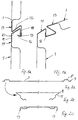
- Fig. 1a und 1b
- die Längsränder zweier Sektionen, ineinandergehakt, zueinander nicht abgewinkelt und abgewinkelt,
- Fig. 2a bis 2c
- Verformungsschritte einer ebenen Blechtafel zu einer Sektion,
- Fig. 3a und 3b
- eine der Fig. 1 ähnliche Darstellung einer abgewandelten Ausführungsform einer Sektion mit mittig der Kastenprofile ausgebildeten Gelenkhaken,
- Fig. 4a bis 4c
- Verformungsschritte einer ebenen Blechbahn zu der Sektion nach Fig. 3,
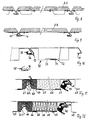
- Fig. 5a und 5b
- eine der Fig. 3 ähnliche Darstellung der Sektionen in nicht abgewinkelter und abgewinkelter Stellung mit jeweils einem in den nicht Z-förmigen Gelenkhaken der unteren Sektion formschlüssig eingreifenden Lagerstück,
- Fig. 6
- eine flache, kastenförmige Laufschiene mit eingesetztem Kunststoff-Gleitelement auf einer Gleitachse, die in das in den Fig. 5a und 5b dargestellte Lagerstück eingeführt wird,
- Fig. 7
- den Querschnitt einer Sektion für ein leichtes Tor ohne Kastenprofile,
- Fig. 8
- das Torblatt nach Fig. 2 mit auf der Außenseite vorgesehenen Holzprofilstäben,
- Fig. 9
- das Torblatt nach Fig. 7 mit auf der Außenseite vorgesehenen Holzpaneelen,
- Fig. 10
- eine weitere Ausführungsform aus einer einzigen Blechtafel mit einem einzigen geschlossenen Kastenprofil,
- Fig. 11
- eine der Fig. 8 ähnliche Ausführungsform, bei der das ausgeschäumte Kastenprofil auf der Innenseite mit einer aufgeschobenen, am Rand gefalzten Blechtafel verschlossen ist, und
- Fig. 12
- eine der Fig. 9 ähnliche Ausführungsform mit unter die Randstreifen des nach innen offenen Kastenprofils eingeschobenen ebenen Blechtafel und Fingerschutzschaumstoff-Formprofil im Bereich der Gelenke.
- 1a and 1b
- the longitudinal edges of two sections, hooked together, not angled and angled to each other,
- 2a to 2c
- Deformation steps of a flat metal sheet into a section,
- 3a and 3b
- 1 similar representation of a modified embodiment of a section with articulated hooks formed in the center of the box profiles,
- 4a to 4c
- Deformation steps of a flat sheet metal sheet to the section according to FIG. 3,
- 5a and 5b
- 3 similar representation of the sections in the non-angled and angled position, each with a positively engaging bearing piece in the non-Z-shaped articulated hook of the lower section,
- Fig. 6
- a flat, box-shaped running rail with an inserted plastic sliding element on a sliding axis, which is inserted into the bearing piece shown in FIGS. 5a and 5b,
- Fig. 7
- the cross section of a section for a light door without box profiles,
- Fig. 8
- 2 with wooden profile bars provided on the outside,
- Fig. 9
- 7 with wooden panels provided on the outside,
- Fig. 10
- another embodiment from a single sheet of metal with a single closed box section,
- Fig. 11
- an embodiment similar to FIG. 8, in which the foamed box section is closed on the inside with a metal sheet which has been pushed on and folded at the edge, and
- Fig. 12
- an embodiment similar to FIG. 9 with a flat sheet of metal inserted under the edge strips of the inwardly open box section and a finger protection foam molded section in the area of the joints.
In Fig. 1 sind zwei benachbarte Sektionen 1 eines Sektionaltors
dargestellt, das aus einer ebenen Blechtafel durch drücken
der Kastenprofile Falten des Längsrandes und Abkanten
mittels der in Fig. 2 dargestellten Abkantschritte hergestellt
wurde. Zunächst werden nahe der Längskanten einer
Blechtafel 2 zwei Kastenprofile 5 durch Drücken gebildet, wie
dies in Fig. 2a dargestellt ist. Dabei verbleiben Randstreifen
7. Als nächstes wird mit größerem Abstand der Kastenprofile
5 jeder Randstreifen nach innen umgebogen bzw. umgefaltet,
wie dies Fig. 2 b zeigt. Dabei entstehen eine äußere
Faltkante 9 und ein doppellagiger Randstreifen 11, der dann
in einem weiteren Abkantschritt zu den in den Fig. 1 und 2
dargestellten komplementären Gelenkhaken 13 und 14 abgekantet
oder gedrückt wird. In diesem Bereich ist die nun fertiggestellte
Sektion zweilagig. Die Gelenkhaken sind ebenso verstärkt
wie der Bereich beiderseits der Kastenprofile 5. Der
Randstreifen 7 liegt an der Blechtafel 3 an und kann hier auf
bekannte Weise befestigt werden, z. B. durch Kleben. Gleiches
gilt für die Außenseite des Kastens im Bereich der Gelenkhaken
13 und 14.In Fig. 1 are two
Wie Fig. 1a und 1b entnehmbar ist, ist der obere Gelenkhaken
13 im Querschnitt Z-förmig ausgebildet. Längs der Außenseite
ist nochmals ein Rand 16 nach innen spiegelbildlich zum Mittelsteg
15 umgebogen, während die Stirnkante 17 des unteren,
nicht Z-förmigen Gelenkhakens 14 hier nach innen zurück zum
Kastenprofil 5 hin weist und der Randstreifen 18 parallel zur
Blechtafel 3 und dem abstehenden Steg 19 verläuft. Der schräge
Verbindungssteg 20 verläuft in der in Fig. 1a dargestellten
Stellung der beiden Sektionen etwa parallel zum Mittelsteg
15 des Gelenkhakens 13. In der in Fig. 1b dargestellten
abgewinkelten Stellung ist das Eingreifen der Stirnkante 17
des unteren Gelenkhakens 14 in den äußeren Grund des Gelenkhakens
13 erkennbar. Die Reibung in diesem Schwenk- bzw. Messerlager
ist äußerst gering.As can be seen in FIGS. 1a and 1b, the upper articulated hook is
13 Z-shaped in cross section. Along the outside
is another
Bei der in Fig. 3 und 4 dargestellten Ausführungsform der
Sektionen stehen die Gelenkhaken 13 und 14 mittig des Kastenprofils
25 von diesem nach außen ab. Um ein solches Kastenprofil
zu erzielen, ist es erforderlich, wie der Fig. 4a entnehmbar
ist, im Randbereich der Blechtafel 3 zwei offene Kastenprofile
26 halber Höhe durch Drücken auszubilden und im
nächsten Abkantschritt die Faltung mittig des Stegs 28 zwischen
den benachbarten Halb-Kastenprofilen 26 vorzunehmen,
um, wie dies Fig. 4b verdeutlicht, ein zur Blechtafel 3 und
der abstehenden Falzfahne 30 symmetrisches quadratisches geschlossenes
Kastenprofil 25 zu erhalten. Im letzten Arbeitsschritt
werden dann die Falzfahnen 30 wieder zu den Gelenkhaken
13 und 14, s. Fig. 4c, umgeformt, um sie ineinander verhaken
zu können, wie sich dies aus Fig. 3a und 3b ergibt. Das
Ineinanderhaken gleicht dem der Sektionen 1 nach Fig. 1. Zwischen
den geschlossenen Kastenprofilen kann parallel zu diesen
eine übliche Längsprofilierung nach Art von Holzprofilstäben
vorgesehen sein, die nicht dargestellt ist.In the embodiment of FIGS. 3 and 4
Sections are the articulated hooks 13 and 14 in the middle of the
In Fig. 3a ist die Bewegungsbahn der inneren Biegekante 31
des Z-förmigen Gelenkhakens 13 als gestrichelter Bogen 32
dargestellt. Man erkennt, daß sich der Spalt gegenüber dem
Mittelsteg 15 des Gelenkhakens 13 wenig öffnet, eine Verletzungsgefahr
durch Einklemmen also nicht gegeben ist und damit
die Vorschriften für einen ausreichenden Fingerschutz erfüllt
sind. Bei der Ausführung nach den Fig. 11 und 12 ist jedoch
noch ein Schaumgummi-Profilstreifen 60 bzw. 61 in die Gelenkhaken
14 bzw. 13 eingeschoben, der entsprechende kanalartige
Längsaussparungen 62 hat, damit das gegenseitige Verschwenken
der Sektionen nicht behindert ist. Sie können durch über die
Seitenwände der Kasteriprofile vorspringende Nasen 63 eines
Abdeckblechs 64 oder am Kastenprofil festgelegte, überstehende,
in zu den Hakengelenken offene Biegefalze 65 eingeschobene
Materialstreifen 66 gesichert sein. 3a is the path of movement of the
Um ein Lösen der ineinandergehakten Sektionen im Betrieb noch
sicherer zu verhindern, werden an den beiden Enden aller Gelenkhaken
14, wie dies in Fig. 5, 11 und 12 dargestellt ist,
Lagerstücke 40 aus Kunststoff eingesetzt. Diese bestehen aus
einem das Profil der Gelenkhaken 14 weitgehend ausfüllenden
blockartigen Kunststoffteil und einem Befestigungsflansch 42,
der mittels einer Schraube 43 an dem Kastenprofil 25 festgelegt
ist. Im Schwenkbereich des Rands 16 des Z-förmigen Gelenkhakens
13 befindet sich eine kanalförmige Aussparung 44,
die dem Rand 16 die nötige Bewegungsfreiheit läßt. Andererseits
ist die untere Begrenzung, s. Fig. 5a, dieser Aussparung
44 so gelegt und gestaltet, daß in der gestreckten
Schwenkstellung nach Fig. 5a der Rand 16 flächig anliegt, wobei
ein Abrutschen nach außen durch eine vorstehende Nase 46
am Lagerstück 40 verhindert wird.To loosen the interlocked sections during operation
Preventing being safer are on both ends of all hinge hooks
14, as shown in FIGS. 5, 11 and 12,
Innerhalb des Hauptteils des Lagerstücks 40 ist eine Lagerbohrung
48 vorgesehen, die der Aufnahme einer Laufrollen- oder
Gleitelementachse 50 dient. Eine solche Achse, die mit
einer Konsole 51 ein Kunststoff-Gleitelement 52 aufnimmt, ist
in Fig. 6 dargestellt. Die Laufschiene 54 ist flach und kastenförmig
ausgebildet, wie es sich aus Fig. 6 ergibt, und
umschließt im erforderlichen Umfang das Gleitelement bzw. den
Gleitstein 52 formschlüssig und läßt ein sehr laufruhiges
Gleiten zur Führung der Sektionen zu. Derartige flache, kastenförmige
Laufschienen 54 lassen sich für die Gestaltung
von Übergangsbögen leicht über Holzschablonen biegen, was
vorteilhafter ist als die noch ganz überwiegend verwendeten
Hochkant-Profilschienen aus Stahl für die Aufnahme von Laufrollen.Inside the main part of the
Für besonders einfache Zwecke und für die Aufbringung von
Holzbelägen jeder Art und Form läßt sich eine Sektion auch
einwandig mit doppelwandigen Randbereichen zur Ausbildung der
Gelenkhaken 13 und 14 ohne Kastenprofile gestalten, wie dies
in den Fig. 7, 8 und 9 dargestellt ist. Durch die Beläge in
Form von Holzprofilbrettern 22 oder Holzpaneelen 23 werden
diese Sektionen genügend versteift. Wegen der auf der Innenseite
befindlichen Blechtafel entspricht dieses Tor auch den
in verschiedenen Ländern bestehenden feuerpolizeilichen Vorschriften.
Der Holzbelag wird von innen angeschraubt.For particularly simple purposes and for the application of
A section can also be made of wood coverings of any type and shape
single-walled with double-walled edge areas to form the
Design articulated hooks 13 and 14 without box profiles, like this
7, 8 and 9. Through the toppings in
Form of wooden profiled
Bei der Ausführung nach Fig. 10 ist ein einziger breiter geschlossener
Profilkasten 70 zwischen den Gelenkhaken 13 und
14 ausgebildet. Dazu ist an jedem Längsrand ein besonders
breiter Randstreifen der Blechtafel umgefaltet und mit Abstand
von der äußeren Faltkante 9 ein Z-förmiger rechtwinkliger
Steg von der Höhe des Profils geformt, wie dies Fig. 10
verdeutlicht. Die einander zugewandten freien Ränder sind
nochmals auf sich zurückgefaltet, wobei die Abmessungen und
die Lage derart gewählt sind, daß die so gebildeten Biegefalze
71, 72 ineinderhakbar sind, um das Profil zu schließen.
Nach Fig. 10 hat die Blechtafel links neben den Falzen eine
Einprägung 73 von der Breite des Biegefalzes 71 an der rechten
Kastenprofilhälfte, um diesen neben dem Biegefalz 72 an
der linken Kastenprofilhälfte so plazieren zu können, daß die
Biegefalze in Eingriff gebracht werden können. In den linken
Gelenkhaken 13 ist ein Gleitprofil 75, sh. auch Detailbild,
mit nach innen vorstehendem Dichtwulst 76 eingelegt, das ein
praktisch geräuschfreies Verschwenken der Gelenkhaken ermöglicht
und zur Abdichtung zwischen den Sektionen beiträgt.In the embodiment according to FIG. 10, there is a single, broadly closed one
Das mit Isolierschaumstoff ausgeschäumte Kastenprofil der
Ausführung nach Fig. 11 unterscheidet sich von der nach Fig.
10 dadurch, daß der zum Z-Profil mit rechten Winkeln geformte
Randstreifen nur ein kurzes Stück nach innen reicht und am
Rand nach außen umgefaltete Falze 65 hat, in die das Abdeckblech
64 mit nach innen gerichteten, zu den Biegefalzen 65
komplementären Biegefalzen 67 zur Schließung des Kastenprofils
eingeschoben ist. Die Biegefalze 67 sind so breit, daß
sie die nach außen überstehende Nase 63 bilden, die die
Schaumstoff-Profilstreifen 60 und 61 unter Spannung festhält.The box profile foamed with insulating foam
The embodiment according to FIG. 11 differs from that according to FIG.
10 in that the formed to the Z-profile with right angles
Edge strips only a short distance inwards and am
Edge folded out folds 65 into which the
Auch das mit Isolationsmatten 68 ausgefüllte, geschlossene
Kastenprofil nach Fig. 12 wird zunächst als offenes Kastenprofil
wie das nach Fig. 11 hergestellt. Es wird dann aber
durch eine Verschlußtafel 69 verschlossen, die unter die nach
innen reichenden Randstreifen mit den nach außen offenen Biegefalzen
65 eingebracht ist. In den in Fig. 12 linken Biegefalz
65 ist der Materialstreifen 66 eingeschoben, der seitlich
über das Kastenprofil vorsteht. Er hält den in das Hakengelenk
13 eingebrachten Schaumstoff-Profilstreifen 60
durch Anlage unter Spannung auf dessen Oberseite sicher fest.
Der profilstreifen 61 für das Hakengelenk 14 befindet sich
nur zwischen den Lagerstücken 40, die an den beiden Enden des
Hakengelenks 14 vorgesehen sind. Diese Lagerstücke 40 sind in
den linken Hälften der Fig. 11 und 12 nicht dargestellt, um
die dahinterliegenden Profilstreifen 61 sichtbar werden zu
lassen. In gleicher Weise wie der Profilstreifen 60 kann der
in das benachbarte Hakengelenk 13 eingebrachte Profilstreifen
61 durch einen in den Biegefalz 65 eingeschobenen Materialstreifen
66 gesichert sein. Bei entsprechend weiter Ausbildung
des Biegefalzes 65 der Ausführungsform nach Fig. 11
könnte dieser Materialstreifen 66 auch unter den Biegefalz 67
der Abdecktafel 64 in den Biegefalz 65 eingeschoben werden.Even the closed one filled with
Claims (13)
dadurch gekennzeichnet,
characterized,
dadurch gekennzeichnet, daß für jede Sektion (1) die eine doppellagige Falzfahne (13) im Querschnitt Z-förmig mit zwei parallel zur Sektionsfläche verlaufenden Querschenkeln und einem diese verbindenden, schräg zur jeweiligen Sektionsfläche verlaufenden Verbindungssteg (15) zu einem Gelenkhaken (13) ausgebildet ist und der endseitige, freie Querschenkel einen zu dem Verbindungssteg (15) hin abgekanteten schmalen Rand (16) aufweist, und
characterized in that for each section (1) the double-layered folded flag (13) in cross-section is Z-shaped with two cross legs running parallel to the section surface and a connecting web (15) connecting them and running obliquely to the respective section surface to form an articulated hook (13) and the free cross leg at the end has a narrow edge (16) folded towards the connecting web (15), and
dadurch gekennzeichnet, daß an jedem Längsrand der Blechtafel (3) ein breiter Randstreifen umgefaltet ist und mit Abstand von der gebildeten Faltkante (9) in den umgefalteten Randstreifen (Falzfahne) ein offenes Kastenprofil (5, 25) mit abstehendem freien Randstreifen (7) zur Anlage, Befestigung und Schließung des Kastenprofils auf dem inneren Bereich der Blechtafel (3) ausgebildet ist und die äußeren Abschnitte zwischen Kastenprofil (5, 25) und Faltkante (9) zu den Gelenkhaken (13, 14) abgekantet sind. (Fig. 2)Door leaf according to claim 3,
characterized in that a wide edge strip is folded over on each longitudinal edge of the metal sheet (3) and an open box profile (5, 25) with a protruding free edge strip (7) in the folded edge strips (folded flag) at a distance from the folded edge (9) formed System, attachment and closure of the box profile is formed on the inner region of the metal sheet (3) and the outer sections between the box profile (5, 25) and the folded edge (9) are folded to the articulated hooks (13, 14). (Fig. 2)
dadurch gekennzeichnet, daß an jedem Längsrand der Blechtafel (3) ein breiter Randstreifen umgefaltet ist und mit Abstand von den gebildeten Faltkanten (9) in den umgefalteten Randstreifen (Falzfahnen) ein Z-förmiger Steg geformt und die freien Enden der parallel zum Mittelteil der Blechtafel verlaufenden freien Randstege zusammen ein geschlossenes Kastenprofil (70) bilden und die freien Randstege der beiden Randstreifen auf sich, einen Abstand belassend, zurückgebogen sind und die so entstandenen, nach außen offenen Biegefalze (71, 72) ineinandergehakt sind. (Fig. 10)Door leaf according to claim 3,
characterized in that a wide edge strip is folded over at each longitudinal edge of the metal sheet (3) and a Z-shaped web is formed in the folded edge strips (folded flags) at a distance from the folded edges (9) formed and the free ends of the webs parallel to the central part of the metal sheet running free edge webs together form a closed box profile (70) and the free edge webs of the two edge strips on themselves, leaving a distance, are bent back and the resulting folding seams (71, 72) open to the outside are hooked together. (Fig. 10)
dadurch gekennzeichnet, daß an jedem Längsrand der Blechtafel (3) ein breiter Randstreifen umgefaltet ist und mit Abstand von den gebildeten Faltkanten (9) in den umgefalteten Randstreifen (Falzfahnen) ein Z-förmiger Steg geformt und die freien Enden der parallel zum Mittelteil der Blechtafel Verlaufenden freien Randstege zusammen ein offenes Kastenprofil bilden und die freien Randstege der beiden Randstreifen auf sich, einen Abstand belassend, zurückgebogen sind und in die so entstandenen nach außen offenen Biegefalze (65) eine Abdecktafel (64) mit längs deren Längsrändern vorgesehenen, nach innen offenen Biegefalzen (67) eingeschoben ist, die das offene Kastenprofil schließt. (Fig. 11)Door leaf according to claim 3,
characterized in that a wide edge strip is folded over at each longitudinal edge of the metal sheet (3) and a Z-shaped web is formed in the folded edge strips (folded flags) at a distance from the folded edges (9) formed and the free ends of the webs parallel to the central part of the metal sheet Running free edge webs together form an open box profile and the free edge webs of the two edge strips are bent back on themselves, leaving a distance, and a cover plate (64) with longitudinally provided longitudinal edges, open inward in the bending folds (65) thus created Bending folds (67) is inserted, which closes the open box profile. (Fig. 11)
dadurch gekennzeichnet, daß wenigstens nahe den Stirnenden der Sektionen (1) in einem Gelenkhaken (14) formschlüssig eingreifende Lagerstücke (40) zur Aufnahme von Laufrollen- oder Gleitelementachsen (50) eingesetzt und vorzugsweise am Kastenprofil (5, 25) gegen Lösen gesichert sind, die eine Aussparung (44) unterhalb des eingezogenen Randes (18) des Gelenkhakens (14) haben, in der der äußere Rand (16) des Z-förmigen Gelenkhakens (13) schwenkbar ist und an deren einer Begrenzungswand anliegt. (Fig. 5, 11, 12Door leaf according to one of claims 1 to 9,
characterized in that at least near the ends of the sections (1) in a hinge hook (14) positively engaging bearing pieces (40) for receiving roller or sliding element axes (50) are inserted and preferably secured on the box profile (5, 25) against loosening, which have a recess (44) below the retracted edge (18) of the articulated hook (14) in which the outer edge (16) of the Z-shaped articulated hook (13) can be pivoted and against which a boundary wall rests. (Fig. 5, 11, 12
dadurch gekennzeichnet, daß das Lagerstück (40) am Außenrand der Begrenzungswand der Aussparung (44), an der der äußere Rand (16) des Z-förmigen Gelenkhakens (13) anliegt, eine in der Aussparung etwas vorstehende Sicherungsnase (46) für den äußeren Rand (16) des Z-förmigen Gelenkhakens (13) aufweist. Door leaf according to claim 10,
characterized in that the bearing piece (40) on the outer edge of the boundary wall of the recess (44) against which the outer edge (16) of the Z-shaped articulated hook (13) abuts, a protruding nose (46) slightly protruding in the recess for the outer Has edge (16) of the Z-shaped hinge hook (13).
dadurch gekennzeichnet, daß die auf einer Gleitelement-Achse (50) gelagerten Gleitelemente (52) im Querschnitt flach rechteckig zum Eingreifen in flache, auf einer Breitseite teilweise offenen, kastenförmige Gleitschienen (54) ausgebildet sind. (Fig. 6)Door leaf according to claim 10 or 11,
characterized in that the sliding elements (52) mounted on a sliding element axis (50) are of flat rectangular cross section for engaging in flat, box-shaped sliding rails (54) which are partially open on a broad side. (Fig. 6)
dadurch gekennzeichnet, daß von der zum Gelenkhaken (13, 14) weisenden Wand (63) des benachbarten Profilkastens ein Materialstreifen (66) oder eine Nase (63) vorsteht oder angeformt ist, hinter denen ein in den Gelenkhaken eingelegter Profilstreifen (60, 61) greift.Door leaf according to one of claims 3 to 13,
characterized in that a material strip (66) or a nose (63) protrudes or is formed from the wall (63) of the adjacent profile box facing the joint hook (13, 14), behind which a profile strip (60, 61) inserted in the joint hook takes hold.
Applications Claiming Priority (2)
| Application Number | Priority Date | Filing Date | Title |
|---|---|---|---|
| DE19937766A DE19937766C2 (en) | 1999-08-10 | 1999-08-10 | Door leaf of a ceiling or side sectional door |
| DE19937766 | 1999-08-10 |
Publications (2)
| Publication Number | Publication Date |
|---|---|
| EP1076149A2 true EP1076149A2 (en) | 2001-02-14 |
| EP1076149A3 EP1076149A3 (en) | 2001-05-16 |
Family
ID=7917872
Family Applications (1)
| Application Number | Title | Priority Date | Filing Date |
|---|---|---|---|
| EP00116268A Withdrawn EP1076149A3 (en) | 1999-08-10 | 2000-08-09 | Door leaf for upwards or sidewards moving sectional door |
Country Status (5)
| Country | Link |
|---|---|
| EP (1) | EP1076149A3 (en) |
| CN (1) | CN1283734A (en) |
| DE (1) | DE19937766C2 (en) |
| HU (1) | HUP0003271A3 (en) |
| PL (1) | PL341929A1 (en) |
Cited By (3)
| Publication number | Priority date | Publication date | Assignee | Title |
|---|---|---|---|---|
| EP1357250A2 (en) * | 2002-04-24 | 2003-10-29 | Wayne-Dalton Corp. | Sectional door system |
| WO2008046818A1 (en) | 2006-10-17 | 2008-04-24 | Hörmann Kg Dissen | Heat-insulating profiled bar for roll-up door curtains, method for the production thereof, and roll-up door comprising the same |
| US8109316B2 (en) | 2009-11-12 | 2012-02-07 | Shih-Hsien Wang | Slat member and fireproof, heat-insulating slat and rolling door |
Families Citing this family (2)
| Publication number | Priority date | Publication date | Assignee | Title |
|---|---|---|---|---|
| DE10211068A1 (en) * | 2002-03-13 | 2003-09-25 | Hoermann Kg | Component for manufacturing a door leaf for a sectional door |
| CN102773262B (en) * | 2012-07-31 | 2014-05-28 | 中国重型机械研究院有限公司 | Rolling mill safety protection device for cold rolling mill |
Citations (2)
| Publication number | Priority date | Publication date | Assignee | Title |
|---|---|---|---|---|
| GB863952A (en) * | 1958-05-12 | 1961-03-29 | Karl Maria Koelbl | Improvements in or relating to a roller-blind of metal or plastic material |
| FR1442079A (en) * | 1965-08-03 | 1966-06-10 | Hunter Douglas | Roll-up curtain, roller shutter or other screen, and blade for their realization |
Family Cites Families (4)
| Publication number | Priority date | Publication date | Assignee | Title |
|---|---|---|---|---|
| DE1269792B (en) * | 1958-05-12 | 1968-06-06 | Karl Maria Koelbl | Shutters made of metal or plastic rods |
| DE2808177C2 (en) * | 1978-02-25 | 1983-04-21 | Th. Kauffmann KG-GmbH & Co Rolladen-Kauffmann, 5000 Köln | Roller shutter slat |
| DE4036410A1 (en) * | 1990-03-12 | 1991-09-19 | Vaw Ver Aluminium Werke Ag | SHAPED ROLLER SHUTTER ROD AND METHOD FOR THE PRODUCTION THEREOF |
| DE19801280C2 (en) * | 1998-01-15 | 2003-03-27 | Erich Doering | Guide and track arrangement of a ceiling or side sectional door or rotary door |
-
1999
- 1999-08-10 DE DE19937766A patent/DE19937766C2/en not_active Expired - Fee Related
-
2000
- 2000-08-09 PL PL00341929A patent/PL341929A1/en not_active IP Right Cessation
- 2000-08-09 EP EP00116268A patent/EP1076149A3/en not_active Withdrawn
- 2000-08-10 HU HU0003271A patent/HUP0003271A3/en unknown
- 2000-08-10 CN CN00124001.3A patent/CN1283734A/en active Pending
Patent Citations (2)
| Publication number | Priority date | Publication date | Assignee | Title |
|---|---|---|---|---|
| GB863952A (en) * | 1958-05-12 | 1961-03-29 | Karl Maria Koelbl | Improvements in or relating to a roller-blind of metal or plastic material |
| FR1442079A (en) * | 1965-08-03 | 1966-06-10 | Hunter Douglas | Roll-up curtain, roller shutter or other screen, and blade for their realization |
Cited By (6)
| Publication number | Priority date | Publication date | Assignee | Title |
|---|---|---|---|---|
| EP1357250A2 (en) * | 2002-04-24 | 2003-10-29 | Wayne-Dalton Corp. | Sectional door system |
| EP1357250A3 (en) * | 2002-04-24 | 2005-03-02 | Wayne-Dalton Corp. | Sectional door system |
| US6951237B2 (en) | 2002-04-24 | 2005-10-04 | Wayne-Dalton Corp. | Sectional door system |
| US7121317B2 (en) | 2002-04-24 | 2006-10-17 | Wayne-Dalton Corp. | Sectional door system |
| WO2008046818A1 (en) | 2006-10-17 | 2008-04-24 | Hörmann Kg Dissen | Heat-insulating profiled bar for roll-up door curtains, method for the production thereof, and roll-up door comprising the same |
| US8109316B2 (en) | 2009-11-12 | 2012-02-07 | Shih-Hsien Wang | Slat member and fireproof, heat-insulating slat and rolling door |
Also Published As
| Publication number | Publication date |
|---|---|
| CN1283734A (en) | 2001-02-14 |
| EP1076149A3 (en) | 2001-05-16 |
| DE19937766C2 (en) | 2001-06-28 |
| HU0003271D0 (en) | 2000-10-28 |
| HUP0003271A3 (en) | 2002-03-28 |
| HUP0003271A2 (en) | 2001-05-28 |
| DE19937766A1 (en) | 2001-03-15 |
| PL341929A1 (en) | 2001-02-12 |
Similar Documents
| Publication | Publication Date | Title |
|---|---|---|
| EP1705335B1 (en) | Cover for roller blind box | |
| DE3825370A1 (en) | POLYCARBONATE SHUTTER DOOR MADE OF HORIZONTAL ELEMENTS | |
| AT7693U1 (en) | HOLDING AND MOUNTING DEVICE FOR A SECTIONAL TORCH | |
| EP3339552B1 (en) | Folding partition with adjusting strip | |
| DD159157A5 (en) | GLIEDERSCHUERZE | |
| WO1995020712A1 (en) | Horizontally sliding window with at least one wing which can move perpendicularly to the plane of the window frame | |
| EP1498382B1 (en) | Lintel for an elevator door | |
| EP0844357B1 (en) | Sectional door having a protective tongue between adjacent panels | |
| DE3021310A1 (en) | Articulated garage type raisable door - has U=sectioned slat shank side hooks forming interconnecting hinges | |
| DE19937766C2 (en) | Door leaf of a ceiling or side sectional door | |
| DE3831521C2 (en) | ||
| WO2008092699A1 (en) | Inspection device, in particular inspection cover | |
| EP0615048B1 (en) | Door or window with a roller shutter box | |
| DE4227311C2 (en) | Panel for a ceiling or side sectional door | |
| DE4031388C2 (en) | Side sectional door or rotary door, ceiling sectional door | |
| EP0128391A2 (en) | Sliding gate movable along a curve | |
| DE202006015290U1 (en) | Window or door fitting e.g. for horizontal or vertical movement of door or windows, provided at wings or framework with cable provided for transmission of signals and or energy | |
| EP0003728B1 (en) | Rolling fire door | |
| DE2839781A1 (en) | WINDOW OR FLAP | |
| DE3050971C3 (en) | Fitting for the sliding sash of windows, doors or the like. | |
| AT504558B1 (en) | Side sliding | |
| EP0480290A1 (en) | Door leaf for sectional or folding doors, especially for garages or hangars, with reinforcing profile members | |
| EP0724063B1 (en) | Rolling door | |
| DE3306429A1 (en) | Folding wall screen | |
| EP0545109A1 (en) | Doorleaf of a ceiling door or a sidesectional door or a concentric running door, in particular for garages or halls |
Legal Events
| Date | Code | Title | Description |
|---|---|---|---|
| PUAI | Public reference made under article 153(3) epc to a published international application that has entered the european phase |
Free format text: ORIGINAL CODE: 0009012 |
|
| AK | Designated contracting states |
Kind code of ref document: A2 Designated state(s): AT BE CH CY DE DK ES FI FR GB GR IE IT LI LU MC NL PT SE |
|
| AX | Request for extension of the european patent |
Free format text: AL;LT;LV;MK;RO;SI |
|
| PUAL | Search report despatched |
Free format text: ORIGINAL CODE: 0009013 |
|
| AK | Designated contracting states |
Kind code of ref document: A3 Designated state(s): AT BE CH CY DE DK ES FI FR GB GR IE IT LI LU MC NL PT SE |
|
| AX | Request for extension of the european patent |
Free format text: AL;LT;LV;MK;RO;SI |
|
| RIC1 | Information provided on ipc code assigned before grant |
Free format text: 7E 06B 3/48 A, 7E 06B 9/15 B |
|
| 17P | Request for examination filed |
Effective date: 20011112 |
|
| AKX | Designation fees paid |
Free format text: AT BE CH CY DE DK ES FI FR GB GR IE IT LI LU MC NL PT SE |
|
| STAA | Information on the status of an ep patent application or granted ep patent |
Free format text: STATUS: THE APPLICATION IS DEEMED TO BE WITHDRAWN |
|
| 18D | Application deemed to be withdrawn |
Effective date: 20040302 |