EP1075997A1 - Verstellmechanismus für eine Lenksäule eines Kraftfahrzeugs - Google Patents
Verstellmechanismus für eine Lenksäule eines Kraftfahrzeugs Download PDFInfo
- Publication number
- EP1075997A1 EP1075997A1 EP00113355A EP00113355A EP1075997A1 EP 1075997 A1 EP1075997 A1 EP 1075997A1 EP 00113355 A EP00113355 A EP 00113355A EP 00113355 A EP00113355 A EP 00113355A EP 1075997 A1 EP1075997 A1 EP 1075997A1
- Authority
- EP
- European Patent Office
- Prior art keywords
- rivet
- packs
- plate packs
- steering column
- casing tube
- Prior art date
- Legal status (The legal status is an assumption and is not a legal conclusion. Google has not performed a legal analysis and makes no representation as to the accuracy of the status listed.)
- Granted
Links
- 241000446313 Lamella Species 0.000 description 6
- 210000002435 tendon Anatomy 0.000 description 6
- 125000006850 spacer group Chemical group 0.000 description 4
- 239000000725 suspension Substances 0.000 description 2
- 229910000639 Spring steel Inorganic materials 0.000 description 1
- 230000000712 assembly Effects 0.000 description 1
- 238000000429 assembly Methods 0.000 description 1
- 230000006835 compression Effects 0.000 description 1
- 238000007906 compression Methods 0.000 description 1
- 238000000034 method Methods 0.000 description 1
Images

Classifications
-
- F—MECHANICAL ENGINEERING; LIGHTING; HEATING; WEAPONS; BLASTING
- F16—ENGINEERING ELEMENTS AND UNITS; GENERAL MEASURES FOR PRODUCING AND MAINTAINING EFFECTIVE FUNCTIONING OF MACHINES OR INSTALLATIONS; THERMAL INSULATION IN GENERAL
- F16B—DEVICES FOR FASTENING OR SECURING CONSTRUCTIONAL ELEMENTS OR MACHINE PARTS TOGETHER, e.g. NAILS, BOLTS, CIRCLIPS, CLAMPS, CLIPS OR WEDGES; JOINTS OR JOINTING
- F16B19/00—Bolts without screw-thread; Pins, including deformable elements; Rivets
- F16B19/04—Rivets; Spigots or the like fastened by riveting
- F16B19/08—Hollow rivets; Multi-part rivets
- F16B19/10—Hollow rivets; Multi-part rivets fastened by expanding mechanically
- F16B19/1027—Multi-part rivets
- F16B19/1036—Blind rivets
- F16B19/1045—Blind rivets fastened by a pull - mandrel or the like
-
- B—PERFORMING OPERATIONS; TRANSPORTING
- B62—LAND VEHICLES FOR TRAVELLING OTHERWISE THAN ON RAILS
- B62D—MOTOR VEHICLES; TRAILERS
- B62D1/00—Steering controls, i.e. means for initiating a change of direction of the vehicle
- B62D1/02—Steering controls, i.e. means for initiating a change of direction of the vehicle vehicle-mounted
- B62D1/16—Steering columns
- B62D1/18—Steering columns yieldable or adjustable, e.g. tiltable
- B62D1/184—Mechanisms for locking columns at selected positions
-
- F—MECHANICAL ENGINEERING; LIGHTING; HEATING; WEAPONS; BLASTING
- F16—ENGINEERING ELEMENTS AND UNITS; GENERAL MEASURES FOR PRODUCING AND MAINTAINING EFFECTIVE FUNCTIONING OF MACHINES OR INSTALLATIONS; THERMAL INSULATION IN GENERAL
- F16B—DEVICES FOR FASTENING OR SECURING CONSTRUCTIONAL ELEMENTS OR MACHINE PARTS TOGETHER, e.g. NAILS, BOLTS, CIRCLIPS, CLAMPS, CLIPS OR WEDGES; JOINTS OR JOINTING
- F16B5/00—Joining sheets or plates, e.g. panels, to one another or to strips or bars parallel to them
- F16B5/04—Joining sheets or plates, e.g. panels, to one another or to strips or bars parallel to them by means of riveting
Definitions
- the invention relates to an adjustment mechanism for a steering column a steering system of a motor vehicle on each Side has at least two intersecting plate packs, which runs through a transverse to a casing tube of the steering column Tendon arrangement can be pressed against each other or from each other are detachable, the plate packs with end receptacles on retaining bolts relative to a part fixed to the vehicle and relative are fixed to the casing tube.
- Such an adjustment mechanism is known from EP 0 802 104 A1.
- the known motor vehicle steering column has a tubular casing on that by means of an adjustment mechanism on a vehicle Console is held.
- the adjustment mechanism is with several Lamella packs are provided, each with several to each other have spaced slats.
- the slats of a slat package are each with a longitudinal slot or with a high slot depending on which adjustment movement of the casing tube, i.e. length or height adjustment, they allow should.
- the slats for the vertical adjustment or the adjustment in the longitudinal direction provided plate packs interpenetrate sandwich-like.
- the elongated holes in the form of the longitudinal slots of the plate packs are from one Tensioning bolts in the transverse direction of the vehicle and thus across the casing tube enforced, which is part of a tendon.
- the tendon allows the slats to be braced against each other or one Release of the fins, so that either fixing the casing tube or a release of the casing tube for a corresponding one Adjustment movement can be adjusted.
- the slats each plate pack is fitted on the end with retaining bolts, with corresponding receptacles for sliding onto the retaining bolts exhibit. Depending on the tolerance of the recordings, it is possible that the slats with little play on each Sitting bolts. This can lead to noise when driving or when adjusting the casing tube.
- the object of the invention is an adjustment mechanism of the beginning to create the kind of a simple means largely silent function guaranteed.
- the holding bolts for positioning the plate packs formed by rivet arrangements are that secure the plate packs form-fitting at the ends.
- the rivet arrangements ensure play-free positioning of the plate packs as a whole as well as the individual Lamellae of each plate pack on the casing tube or on the vehicle-fixed part, so that noise coming from a corresponding Play in the area of the recordings of the slats resulted can be reliably avoided.
- the plate packs can also from only two slats each, preferably in the form of spring steel sheets. The positive locking in the longitudinal direction of the retaining bolts and thus the rivet arrangements also prevents unintentional detachment from the casing tube or from the vehicle-fixed part.
- each rivet arrangement on the one hand a backlash-free bracket radial to the longitudinal direction of each rivet arrangement and thus in the Level of each inclusion of the slats of the slat packs. Moreover is also in the longitudinal direction of the rivet arrangements and thus across the lamellae of the lamella packs have a form-fitting backing, which also guarantees freedom of play in this direction.
- the provision of basically known rivet arrangements also ensures the assembly and fixing of the slats each plate pack on the vehicle-fixed part or on the Jacket tube from a single mounting side. This will the assembly of the adjustment mechanism facilitated.
- the rivet arrangements are of this type excited to see that the rivet shafts of the rivet arrangements are free of play Fit the ends of the slats.
- the sleeve-like The rivet shafts of the rivet arrangements deform in such a way that they complete the end shots of the disk packs to complete.
- a spacer can replace several slats and also in the slat package create a gap, the space for the arrangement of others Creates components.
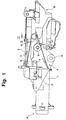
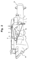
- a steering column for a passenger car has according to the Fig. 1 and 2 on a casing tube 1, in which in not shown Way a steering spindle is rotatably mounted.
- the casing tube 1 is fixed to a vehicle by means of an adjustment mechanism 3 Console 2 held adjustable.
- the vehicle is fixed Console 2 on a - seen in the direction of travel - front End region B of the casing tube 1 is an unspecified rider-shaped suspension on which the casing tube 1 is held is.
- One to the opposite end region A on the steering wheel side of the casing tube 1 offset rear suspension is by the adjustment mechanism 3 described in more detail below.
- the adjustment mechanism 3 has on opposite sides of the jacket tube 1 each have a plate pack 4, the jacket tube side is set. In addition, each is on the jacket pipe side Lamella pack 4 assigned a bracket-side disk pack 5, which is fixed to the vehicle-fixed console 2.
- the individual slats of the plate packs 4, 4a, 5 on each side of the casing tube 1 alternate and sandwich, the console-side plate packs 5 with - relative to Console seen - elongated hole cutouts running in the vertical direction 7 are provided.
- the lamella packs 4 on the jacket pipe side, 4a have elongated hole cutouts running approximately in the longitudinal direction of the casing tube 6 on which the slot recesses 7 of the plate packs 5 cross.
- the plate packs 4, 4a, 5 are of a small number Number of individual slats, preferably of two slats, composed. In the intersecting area of the slot cutouts 6, 7 these are penetrated by a clamping bolt, the part of a tendon arrangement of the adjusting mechanism 3 is.
- the clamping bolt of a tendon arrangement runs transversely to Spindle axis of the steering spindle of the casing tube 1 and thus approximately in the vehicle transverse direction.
- All slats are in corner or edge sections and thus at the ends the plate packs 4, 4a, 5 each with at least one Provide recording in the form of a circular recess, the to fix the respective slat using a retaining bolt in the form of a rivet arrangement 8, 9 on the respective component, i.e. on the console 2 or on the jacket tube 1, is used.
- the rivet arrangements 8, 9 are designed such that they the individual slats the plate packs 4, 4a, 5 in the area of the respective breakpoints backlash-free both along the mounting axis and radially and thus transversely to the fastening axis of each rivet arrangement 8, 9 secure.
- a major advantage of the rivet arrangements 8, 9 is it that the assembly of the rivet assemblies 8 from one side and thus preferably in each case in the present exemplary embodiment can be done from the outside without any counter holding on the inside during assembly a tool or a corresponding handle can be created got to.
- the freedom of play along the mounting axis takes place by a corresponding tensioning of the rivet arrangement 8, 9 in the pulling direction Z (FIG. 4), with a rivet head 14 on the one hand and a deformed front end of a rivet shaft 13 the rivet assembly 8, 9 on the other hand, the corresponding positive form effective end stops.
- the rivet shank 13 is also at its Compression due to the tensile load in the direction of arrow Z of the tension rod 12 expanded so that he the available Cutouts in the receptacles 11 of the lamellae of the lamella packs 4, 4a and 5 and the casing tube 1 and the vehicle-fixed console 2 completely fills in accordance with FIG. 5.
- This will make the one you want Clearance across the mounting axis of the respective rivet arrangement 8, 9 created so that the slats of the plate packs 4, 4a, 5 in the blocked position next to the frictional pressing also by a corresponding play-free form fit in the area the breakpoints are held.
- a plate pack 5 also from a combination of slats with a spacer sleeve 10 build up between two subpackages of slats of the plate pack 5 extends, and the coaxial the rivet assembly 8 is positioned.
- This spacer sleeve too 10 is held without play on the rivet shaft of the rivet arrangement 8, as soon as the rivet assembly 8 is clamped into its functional position is.
Landscapes
- Engineering & Computer Science (AREA)
- General Engineering & Computer Science (AREA)
- Mechanical Engineering (AREA)
- Chemical & Material Sciences (AREA)
- Combustion & Propulsion (AREA)
- Transportation (AREA)
- Steering Controls (AREA)
- Insertion Pins And Rivets (AREA)
Abstract
Description
- Fig. 1
- zeigt in perspektivischer Darstellung ein Mantelrohr einer Lenksäule eines Kraftfahrzeugs, das mittels einer Ausführungsform eines erfindungsgemäßen Verstellmechanismus an einer fahrzeugfesten Konsole positioniert ist,
- Fig. 2
- eine weitere perspektivische Darstellung des Mantelrohres nach Fig. 1 von der gegenüberliegenden Seite her,
- Fig. 3
- einen Ausschnitt des Verstellmechanismus für das Mantelrohr nach den Fig. 1 und 2 längs der Schnittebene III-III in Fig. 1,
- Fig. 4
- in vergrößerter, schematischer Schnittdarstellung einen Montagevorgang zur Festlegung eines Lamellenpaketes des Verstellmechanismus an einem stationären Bauteil, und
- Fig. 5
- die Schnittdarstellung nach Fig. 4, jedoch in fertig montiertem Zustand der Lamellenpakete und der Nietanordnung.
Claims (3)
- Verstellmechanismus für eine Lenksäule einer Lenkungsanlage eines Kraftfahrzeugs, der auf jeder Seite wenigstens zwei sich kreuzende Lamellenpakete aufweist, die durch ein quer zu einem Mantelrohr der Lenksäule verlaufende Spanngliedanordnung gegeneinander preßbar oder voneinander lösbar sind, wobei die Lamellenpakete mit endseitigen Aufnahmen auf Haltebolzen relativ zu einem fahrzeugfesten Teil oder relativ zu dem Mantelrohr festgelegt sind,
dadurch gekennzeichnet,
daß die Haltebolzen zur Positionierung der Lamellenpakete (4, 4a, 5) durch Nietanordnungen (8, 9) gebildet sind, die die Lamellenpakete (4, 4a, 5) endseitig jeweils formschlüssig sichern. - Verstellmechanismus nach Anspruch 1,
dadurch gekennzeichnet,
daß die Nietanordnungen (8, 9) derart gespannt sind, daß Nietschäfte (13) der Nietanordnungen (8, 9) sich spielfrei in die endseitigen Aufnahmen (11) der Lamellenpakete (4, 4a, 5) einpassen. - Verstellmechanismus nach Anspruch 1 oder 2,
dadurch gekennzeichnet,
daß zwischen Lamellen eines Lamellenpaketes (5) wenigstens eine koaxial die Nietanordnung (8) übergreifende Abstandshülse (10) vorgesehen ist.
Applications Claiming Priority (2)
| Application Number | Priority Date | Filing Date | Title |
|---|---|---|---|
| DE19933674A DE19933674B4 (de) | 1999-07-17 | 1999-07-17 | Verstellmechanismus für eine Lenksäule eines Kraftfahrzeugs |
| DE19933674 | 1999-07-17 |
Publications (2)
| Publication Number | Publication Date |
|---|---|
| EP1075997A1 true EP1075997A1 (de) | 2001-02-14 |
| EP1075997B1 EP1075997B1 (de) | 2002-04-17 |
Family
ID=7915207
Family Applications (1)
| Application Number | Title | Priority Date | Filing Date |
|---|---|---|---|
| EP00113355A Expired - Lifetime EP1075997B1 (de) | 1999-07-17 | 2000-06-23 | Verstellmechanismus für eine Lenksäule eines Kraftfahrzeugs |
Country Status (3)
| Country | Link |
|---|---|
| EP (1) | EP1075997B1 (de) |
| DE (2) | DE19933674B4 (de) |
| ES (1) | ES2174787T3 (de) |
Families Citing this family (2)
| Publication number | Priority date | Publication date | Assignee | Title |
|---|---|---|---|---|
| GB2433090A (en) * | 2005-12-08 | 2007-06-13 | Nsk Steering Sys Europ Ltd | Pivot connection device, steering assembly and method for assembling a steering assembly |
| DE102018111049A1 (de) | 2018-05-08 | 2019-11-14 | Böllhoff Verbindungstechnik GmbH | Verbindung zwischen zwei bauteilen mit toleranzausgleich sowie ein verbindungsverfahren hierfür |
Citations (2)
| Publication number | Priority date | Publication date | Assignee | Title |
|---|---|---|---|---|
| EP0802104A1 (de) * | 1996-04-18 | 1997-10-22 | Etablissement Supervis | Lenksäule für Kraftfahrzeuge |
| DE19638051C1 (de) * | 1996-09-18 | 1998-03-05 | Lemfoerder Metallwaren Ag | Lenksäulenbaueinheit |
-
1999
- 1999-07-17 DE DE19933674A patent/DE19933674B4/de not_active Expired - Fee Related
-
2000
- 2000-06-23 DE DE50000142T patent/DE50000142D1/de not_active Expired - Lifetime
- 2000-06-23 EP EP00113355A patent/EP1075997B1/de not_active Expired - Lifetime
- 2000-06-23 ES ES00113355T patent/ES2174787T3/es not_active Expired - Lifetime
Patent Citations (2)
| Publication number | Priority date | Publication date | Assignee | Title |
|---|---|---|---|---|
| EP0802104A1 (de) * | 1996-04-18 | 1997-10-22 | Etablissement Supervis | Lenksäule für Kraftfahrzeuge |
| DE19638051C1 (de) * | 1996-09-18 | 1998-03-05 | Lemfoerder Metallwaren Ag | Lenksäulenbaueinheit |
Also Published As
| Publication number | Publication date |
|---|---|
| ES2174787T3 (es) | 2002-11-16 |
| DE50000142D1 (de) | 2002-05-23 |
| DE19933674A1 (de) | 2001-01-25 |
| DE19933674B4 (de) | 2005-07-21 |
| EP1075997B1 (de) | 2002-04-17 |
Similar Documents
| Publication | Publication Date | Title |
|---|---|---|
| DE69607421T2 (de) | System zur Führung und Verriegelung für eine Kraftfahrzeuglenksäule | |
| DE69616193T2 (de) | Energieaufnehmende und führende Einrichtung für die Lenksäule eines Kraftfahrzeugs | |
| DE3104681C2 (de) | Kraftfahrzeugtür aus Kunststoff | |
| EP0711231B1 (de) | Überrollbügeleinrichtung mit innenführung und aussenführung | |
| DE69006990T2 (de) | Träger für eine Lenksäule. | |
| EP0802104A1 (de) | Lenksäule für Kraftfahrzeuge | |
| DE19708215A1 (de) | Schweller eines Kraftfahrzeugs mit einer Verstärkungseinlage | |
| DE10238750A1 (de) | Angetriebene Schlittenvorrichtung für einen Sitz | |
| EP4100279B1 (de) | Längseinsteller und fahrzeugsitz | |
| DE19836425A1 (de) | Sitzgestell eines verstellbaren Fahrzeugsitzes | |
| DE102020126146B4 (de) | Windschutzvorrichtung für ein fahrzeug | |
| EP2040970B1 (de) | Anordnung zur befestigung einer lenksäule eines kraftfahrzeuges | |
| EP1493634A1 (de) | Airbagmodul mit Gehäuse für die Aufnahme mindestens eines Gasgenerators und mindestens eines Gassacks | |
| DE102008038848A1 (de) | Seitenteil für einen Sitzträger eines Fahrzeugsitzes, sowie Sitzträger | |
| EP0903265A2 (de) | Energieabsorptionsvorrichtung für ein Kraftfahrzeug | |
| DE1505481B2 (de) | Fahrzeugsitz | |
| DE102006013226B4 (de) | Fahrzeugchassis-Frontaufbau | |
| DE102019125196A1 (de) | Längseinsteller, fahrzeugsitz | |
| EP1075997B1 (de) | Verstellmechanismus für eine Lenksäule eines Kraftfahrzeugs | |
| DE102020130226B4 (de) | Längseinsteller, Fahrzeugsitz | |
| EP1122121B1 (de) | Transportbehälter-Einrichtung für den Einbau in Kraftfahrzeuge, wie z.B. Durchladeeinrichtung | |
| DE10045806B4 (de) | Sitzlängsverstellung für einen Kraftfahrzeugsitz | |
| DE3608828A1 (de) | Vorrichtung zur veraenderung der nutzbaren sitzflaeche des sitzteils eines fahrzeugsitzes | |
| DE19720856C2 (de) | Als Rammschutz ausgebildete Trittstufe für Kraftfahrzeuge | |
| DE19933677B4 (de) | Lenkungsanlage für ein Kraftfahrzeug |
Legal Events
| Date | Code | Title | Description |
|---|---|---|---|
| PUAI | Public reference made under article 153(3) epc to a published international application that has entered the european phase |
Free format text: ORIGINAL CODE: 0009012 |
|
| AK | Designated contracting states |
Kind code of ref document: A1 Designated state(s): DE ES FR GB IT SE |
|
| AX | Request for extension of the european patent |
Free format text: AL;LT;LV;MK;RO;SI |
|
| 17P | Request for examination filed |
Effective date: 20010322 |
|
| GRAG | Despatch of communication of intention to grant |
Free format text: ORIGINAL CODE: EPIDOS AGRA |
|
| GRAG | Despatch of communication of intention to grant |
Free format text: ORIGINAL CODE: EPIDOS AGRA |
|
| GRAH | Despatch of communication of intention to grant a patent |
Free format text: ORIGINAL CODE: EPIDOS IGRA |
|
| 17Q | First examination report despatched |
Effective date: 20010917 |
|
| AKX | Designation fees paid |
Free format text: DE ES FR GB IT SE |
|
| REG | Reference to a national code |
Ref country code: GB Ref legal event code: IF02 |
|
| GRAH | Despatch of communication of intention to grant a patent |
Free format text: ORIGINAL CODE: EPIDOS IGRA |
|
| GRAA | (expected) grant |
Free format text: ORIGINAL CODE: 0009210 |
|
| AK | Designated contracting states |
Kind code of ref document: B1 Designated state(s): DE ES FR GB IT SE |
|
| REF | Corresponds to: |
Ref document number: 50000142 Country of ref document: DE Date of ref document: 20020523 |
|
| GBT | Gb: translation of ep patent filed (gb section 77(6)(a)/1977) |
Effective date: 20020712 |
|
| ET | Fr: translation filed | ||
| REG | Reference to a national code |
Ref country code: ES Ref legal event code: FG2A Ref document number: 2174787 Country of ref document: ES Kind code of ref document: T3 |
|
| PLBE | No opposition filed within time limit |
Free format text: ORIGINAL CODE: 0009261 |
|
| STAA | Information on the status of an ep patent application or granted ep patent |
Free format text: STATUS: NO OPPOSITION FILED WITHIN TIME LIMIT |
|
| 26N | No opposition filed |
Effective date: 20030120 |
|
| PGFP | Annual fee paid to national office [announced via postgrant information from national office to epo] |
Ref country code: ES Payment date: 20080627 Year of fee payment: 9 |
|
| PGFP | Annual fee paid to national office [announced via postgrant information from national office to epo] |
Ref country code: IT Payment date: 20080623 Year of fee payment: 9 |
|
| PGFP | Annual fee paid to national office [announced via postgrant information from national office to epo] |
Ref country code: SE Payment date: 20080612 Year of fee payment: 9 |
|
| PGFP | Annual fee paid to national office [announced via postgrant information from national office to epo] |
Ref country code: FR Payment date: 20080613 Year of fee payment: 9 |
|
| PGFP | Annual fee paid to national office [announced via postgrant information from national office to epo] |
Ref country code: GB Payment date: 20080620 Year of fee payment: 9 |
|
| REG | Reference to a national code |
Ref country code: FR Ref legal event code: CD Ref country code: FR Ref legal event code: CA |
|
| GBPC | Gb: european patent ceased through non-payment of renewal fee |
Effective date: 20090623 |
|
| REG | Reference to a national code |
Ref country code: FR Ref legal event code: ST Effective date: 20100226 |
|
| PG25 | Lapsed in a contracting state [announced via postgrant information from national office to epo] |
Ref country code: FR Free format text: LAPSE BECAUSE OF NON-PAYMENT OF DUE FEES Effective date: 20090630 |
|
| PG25 | Lapsed in a contracting state [announced via postgrant information from national office to epo] |
Ref country code: GB Free format text: LAPSE BECAUSE OF NON-PAYMENT OF DUE FEES Effective date: 20090623 |
|
| REG | Reference to a national code |
Ref country code: ES Ref legal event code: FD2A Effective date: 20090624 |
|
| PG25 | Lapsed in a contracting state [announced via postgrant information from national office to epo] |
Ref country code: ES Free format text: LAPSE BECAUSE OF NON-PAYMENT OF DUE FEES Effective date: 20090624 |
|
| PG25 | Lapsed in a contracting state [announced via postgrant information from national office to epo] |
Ref country code: IT Free format text: LAPSE BECAUSE OF NON-PAYMENT OF DUE FEES Effective date: 20090623 |
|
| PG25 | Lapsed in a contracting state [announced via postgrant information from national office to epo] |
Ref country code: SE Free format text: LAPSE BECAUSE OF NON-PAYMENT OF DUE FEES Effective date: 20090624 |
|
| REG | Reference to a national code |
Ref country code: DE Ref legal event code: R081 Ref document number: 50000142 Country of ref document: DE Owner name: ORBACH, GREGOR, DIPL.ING., DE Free format text: FORMER OWNER: DAIMLER AG, 70327 STUTTGART, DE Effective date: 20140805 |
|
| PGFP | Annual fee paid to national office [announced via postgrant information from national office to epo] |
Ref country code: DE Payment date: 20151109 Year of fee payment: 16 |
|
| REG | Reference to a national code |
Ref country code: DE Ref legal event code: R119 Ref document number: 50000142 Country of ref document: DE |
|
| PG25 | Lapsed in a contracting state [announced via postgrant information from national office to epo] |
Ref country code: DE Free format text: LAPSE BECAUSE OF NON-PAYMENT OF DUE FEES Effective date: 20170103 |