EP1075627B1 - Dampferzeuger betriebsverfahren - Google Patents
Dampferzeuger betriebsverfahren Download PDFInfo
- Publication number
- EP1075627B1 EP1075627B1 EP99920121A EP99920121A EP1075627B1 EP 1075627 B1 EP1075627 B1 EP 1075627B1 EP 99920121 A EP99920121 A EP 99920121A EP 99920121 A EP99920121 A EP 99920121A EP 1075627 B1 EP1075627 B1 EP 1075627B1
- Authority
- EP
- European Patent Office
- Prior art keywords
- air
- flue gas
- stream
- excess
- recited
- Prior art date
- Legal status (The legal status is an assumption and is not a legal conclusion. Google has not performed a legal analysis and makes no representation as to the accuracy of the status listed.)
- Expired - Lifetime
Links
Images





Classifications
-
- F—MECHANICAL ENGINEERING; LIGHTING; HEATING; WEAPONS; BLASTING
- F23—COMBUSTION APPARATUS; COMBUSTION PROCESSES
- F23J—REMOVAL OR TREATMENT OF COMBUSTION PRODUCTS OR COMBUSTION RESIDUES; FLUES
- F23J15/00—Arrangements of devices for treating smoke or fumes
- F23J15/08—Arrangements of devices for treating smoke or fumes of heaters
-
- F—MECHANICAL ENGINEERING; LIGHTING; HEATING; WEAPONS; BLASTING
- F22—STEAM GENERATION
- F22D—PREHEATING, OR ACCUMULATING PREHEATED, FEED-WATER FOR STEAM GENERATION; FEED-WATER SUPPLY FOR STEAM GENERATION; CONTROLLING WATER LEVEL FOR STEAM GENERATION; AUXILIARY DEVICES FOR PROMOTING WATER CIRCULATION WITHIN STEAM BOILERS
- F22D1/00—Feed-water heaters, i.e. economisers or like preheaters
- F22D1/36—Water and air preheating systems
-
- F—MECHANICAL ENGINEERING; LIGHTING; HEATING; WEAPONS; BLASTING
- F23—COMBUSTION APPARATUS; COMBUSTION PROCESSES
- F23J—REMOVAL OR TREATMENT OF COMBUSTION PRODUCTS OR COMBUSTION RESIDUES; FLUES
- F23J15/00—Arrangements of devices for treating smoke or fumes
- F23J15/006—Layout of treatment plant
-
- F—MECHANICAL ENGINEERING; LIGHTING; HEATING; WEAPONS; BLASTING
- F23—COMBUSTION APPARATUS; COMBUSTION PROCESSES
- F23L—SUPPLYING AIR OR NON-COMBUSTIBLE LIQUIDS OR GASES TO COMBUSTION APPARATUS IN GENERAL ; VALVES OR DAMPERS SPECIALLY ADAPTED FOR CONTROLLING AIR SUPPLY OR DRAUGHT IN COMBUSTION APPARATUS; INDUCING DRAUGHT IN COMBUSTION APPARATUS; TOPS FOR CHIMNEYS OR VENTILATING SHAFTS; TERMINALS FOR FLUES
- F23L15/00—Heating of air supplied for combustion
- F23L15/02—Arrangements of regenerators
-
- F—MECHANICAL ENGINEERING; LIGHTING; HEATING; WEAPONS; BLASTING
- F23—COMBUSTION APPARATUS; COMBUSTION PROCESSES
- F23J—REMOVAL OR TREATMENT OF COMBUSTION PRODUCTS OR COMBUSTION RESIDUES; FLUES
- F23J2217/00—Intercepting solids
- F23J2217/10—Intercepting solids by filters
- F23J2217/102—Intercepting solids by filters electrostatic
-
- F—MECHANICAL ENGINEERING; LIGHTING; HEATING; WEAPONS; BLASTING
- F23—COMBUSTION APPARATUS; COMBUSTION PROCESSES
- F23J—REMOVAL OR TREATMENT OF COMBUSTION PRODUCTS OR COMBUSTION RESIDUES; FLUES
- F23J2217/00—Intercepting solids
- F23J2217/50—Intercepting solids by cleaning fluids (washers or scrubbers)
-
- Y—GENERAL TAGGING OF NEW TECHNOLOGICAL DEVELOPMENTS; GENERAL TAGGING OF CROSS-SECTIONAL TECHNOLOGIES SPANNING OVER SEVERAL SECTIONS OF THE IPC; TECHNICAL SUBJECTS COVERED BY FORMER USPC CROSS-REFERENCE ART COLLECTIONS [XRACs] AND DIGESTS
- Y02—TECHNOLOGIES OR APPLICATIONS FOR MITIGATION OR ADAPTATION AGAINST CLIMATE CHANGE
- Y02E—REDUCTION OF GREENHOUSE GAS [GHG] EMISSIONS, RELATED TO ENERGY GENERATION, TRANSMISSION OR DISTRIBUTION
- Y02E20/00—Combustion technologies with mitigation potential
- Y02E20/34—Indirect CO2mitigation, i.e. by acting on non CO2directly related matters of the process, e.g. pre-heating or heat recovery
Definitions
- the present invention relates to a method for improving the performance of particulate collection devices in coal fired steam generating plants. More specifically the invention relates to the control of the temperature of the flue gas flowing from the air preheater to an electrostatic precipitator or baghouse filter.
- Coal fired steam generating plants employ air preheaters to transfer heat from the flue gas to the incoming combustion air and many employ electrostatic precipitators or baghouse filters downstream from the air preheater to remove the particulate fly ash from the flue gas prior to discharge.
- the temperature of the flue gas entering the electrostatic precipitator or baghouse can have a significant impact on the collection efficiency.
- the so-called back corona in the electrostatic precipitator can be a major source of increased particulate emissions for high resistivity fly ash and the flue gas temperature can significantly impact the back corona effect.
- the flue gas temperature can significantly affect the caking properties of the fly ash in baghouse fabric filters.
- DE 43 27476 Al discloses an apparatus for generating steam including a steam boiler having a flue gas heat exchanger for preheating outside air and providing heat to a row of preheating devices for preheating feed water, especially by the performance of the process.
- a steam boiler having a flue gas heat exchanger for preheating outside air and providing heat to a row of preheating devices for preheating feed water, especially by the performance of the process.
- at least one air-water heat exchanger (11,17) is arranged, which is operable to receive heat from air which has been heated in a flue gas heat exchanger (4,21,22).
- a heated air recirculation element (6b,20,23,25) is arranged relative to a flue gas heat exchanger (11,17,22) and an outside air inlet (7) and the air-water heat exchanger (17,11) is communicated with the heater air recirculation element (6b,20,23,25).
- U.S. Patent No. 4,090,455 to McCartney discloses a furnace 10 having a 60 coal fired burner 12 exhausts hot oxygen deficient products of combustion through an outlet 14, an exhaust duct 16 and heat exchanger 18 to a dust collector 22 where particulate matter is removed therefrom before residual clean gas is exhausted through outlet 24 to the 65 atmosphere.
- An independent burner 36 for high energy fuel such as gas or oil is combined with a heat exchanger 38 whereby air flowing through the heat exchanger and being indirectly heated by the burner 36 passes on through duct 42 and is exhausted into duct 28 in advance of a pulverizing and drying mill 32.
- hot gases from the burner 36 transfer their heat to a quantity of air traversing heat exchanger 38 whereby it comprises sufficient hot primary air to heat and dry the pulverized coal in mill 32 as required for efficient combustion of the coal.
- the requirements for the quantity and temperature of the primary and secondary combustion air and the design of the air preheater have a basic effect on the flue gas temperature leaving the air preheater.
- the temperature of the flue gas leaving the air preheater cold end needs to be controlled to avoid condensation and plugging.
- the present invention relates to the reduction of the flue gas temperature coming from an air preheater to a particulate collection device comprising an electrostatic precipitator or fabric filter. More specifically, the invention involves modifying the operation of the air preheater to reduce the exit flue gas temperature and/or reducing the flue gas temperature after exiting the air preheater but prior to the particulate collection device. In modifying the air preheater operation, the air mass flow through the air preheater is increased in excess of that required for combustion and then using that excess air for one or more of a variety of purposes in the plant other than combustion or merely dumping the excess air.
- a method of operating a steam generating system including a steam generator which generates a flue gas stream, an air preheater which transfers heat from said flue gas stream to an incoming air stream to produce a heated air stream, and a particulate control device for removing particulates from said flue gas stream.
- the method comprises the steps of passing a quantity of air through the air preheater wherein the air is heated, the quantity of air being selected to provide a desired flue gas temperature for operation of the particulate control device and including a first portion comprising combustion air and a second portion comprising excess air and withdrawing the quantity of heated air from the air preheater.
- the method also includes the steps of passing the first portion of heated air to the steam generator as combustion air and passing the second portion of heated air around the steam generator as excess air. Additionally, the method includes the step of transferring heat from the excess heated air to the flue gas discharged from the flue gas scrubber to reheat the discharged flue gas.
- One aspect of the invention involves a method of obtaining a relatively clean excess air stream to reduce particulate emissions by segmenting the air outlet side of a rotary regenerative air preheater and withdrawing the excess air from the segment where the dust loading is the lowest. Additional air may also be passed through the air preheater by reducing the quantity of primary air that bypasses the air preheater and providing other ways to control the temperature of the primary air to the pulverizers.
- a further method of controlling the flue gas temperature to the particulate collection device is to cool the flue gas after it passes through the air preheater by heat exchange with a cooler steam generator stream or by spray cooling with water. The cooling after the air preheater can be used alone or it can be used in conjunction with the modification of the air preheater operation.
- a further aspect of the invention is the control of the process to maintain the desired temperature in response to the various system parameters.
- the capacity-rate of the air (C A ) and the capacity-rate of the flue gas (C G ) as well as the air side effectiveness (E A ) and gas side effectiveness (E G ) control the operation.
- the capacity-rate is the product of the mass flow times the specific heat of the medium.
- the mass flow of the air and the specific heat of the air are each less than the corresponding values for the gas streàm.
- the air flow rate may be 588.41 kilogram/second (4,670,000 lb./hr.) with a specific heat of 1.034 kilojoule/kilogram kelvin (0.247 BTU/lb. °F) while the gas flow rate may be 705.59 kilogram/second (5,600,000 lb./hr.) with a specific heat of 1.105 kilojoule/kilogram kelvin (0.264BTU/16.°F).
- an E A above 0.9 requires a very large air preheater surface area increase.
- a C A /C G of 0.8 to go from an E A of 0.909 up to 0.93 (an increase of 2.3%) requires an 18% increase in surface area.
- an E A of 0.909 equals an E G of 0.709 (0.909 x 0.78) which results in a TGO of 132.78°C (271°F) and TAO of 365°C (689°F).
- the method for increasing C A /C G is to increase the mass flow of air and then "dump" the excess heated air which is not needed for combustion.
- Dumping the excess air usually involves using the heated air somewhere in the plant.
- One of the uses for heated air is to reheat the saturated flue gases leaving a scrubber prior to discharge up the stack to aid in buoyancy and reduce plume visibility.
- a potential problem with using excess air from the air preheater for this purpose or any other purpose where the excess air is to be discharged to the atmosphere is that it is often contains significant amounts of particulate material which could restrict its use because of emission limits.
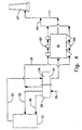
- FIG. 1 of the drawings illustrates in schematic form a steam generator system including a steam generator 12, an air preheater 14, an electrostatic precipitator 16, a flue gas scrubber 18 and a stack gas reheater 20.
- This arrangement of components is typical of steam generator systems and particularly of coal fired steam generators where electrostatic precipitators are used to remove particulates from the flue gas and scrubbers are used to remove gaseous pollutants.
- the flue gas 22 transfers heat to the heat exchange surface in the flue gas side 24 of the air preheater 14 and this heat is picked up by the incoming air 26 in the air side 28 of the air preheater 14. Most of the heated air is used for primary combustion air 30 and secondary combustion air 32. The third heated air stream 34 will be explained hereinafter.
- the flue gas 17 from the electrostatic precipitator 16 is scrubbed at 18 and reheated at 20.
- a heat transfer device 20 such as a steam coil reheater or a burner may be used for transferring heat to the flue gas.
- the use of the excess air together with the heat transfer device 20 will reduce the size that otherwise would be required for the heat transfer device.
- the excess air stream 34 may merely be dumped to atmosphere at 35. If desired, this dump air 35 may be cleaned such as by a filter 33. Since the flow rate of the dump air 35 may be small, only a small filter device would be needed.
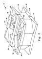
- FIG 1 is a perspective view of an air preheater 14 constructed in accordance with this embodiment of the present invention.
- the air preheater comprises the rotor 36, the rotor housing 38, the gas inlet and outlet connecting plate duct assemblies 40 and 42 respectively and the air inlet and outlet connecting plate duct assemblies 44 and 46 respectively.
- These connecting plate duct assemblies form the connections and the transition between the duct work and the generally circular or polygonal rotor housing 38.
- the illustrated rotor is of a conventional type which is divided into sectors by the rotor diaphragms 48 and with these sectors being further divided into compartments by the stay plates 50.
- the air preheater is divided into a gas side and an air side by the usual sector plates 52 on the top and bottom (not shown) of the rotor.
- the upper and lower center sections 54 and 56 are adjacent the upper and lower ends of the rotor between the air side and the gas side.
- Various other detailed components of a typical air preheater would be included, even though not shown, such as radial and axial seals to reduce the leakage of air and gas between the sectors.
- the air preheater used in this embodiment of the present invention is equipped with means to segregate that portion of the heated air flow which comprises the dump air.
- This is shown in Figure 2 as the partition 58 which extends generally radially across the air outlet connecting plate duct assembly 46.
- This partition 58 is located to segregate the desired portion of the total air flow as dump air.
- Suitable ducting means would then route this segregated dump air, which is designated as 34 in Figure 1, to the desired location for the end use of the dump air such as reheating the flue gas.
- the partition is located such that the dump air is withdrawn from the last portion of the air side before the rotor re-enters the gas side.
- the partition 58 would be located so that it segregates approximately 10% of the flow area of the air outlet connecting plate duct assembly 46. The remaining 90% would be connected to the duct work supplying the combustion air to the furnace.
- Figure 3 is one of the alternate embodiments of the present invention which can be used where insufficient particulates are removed from the rotor in the beginning of the passage through the air side and excessive particulates are being picked up by the dump air.
- the air velocity in the first section of the air side can be boosted to help shear the particulates in the location farthest from the dump air section.
- This is illustrated diagrammatically in Figure 3 by the three incoming air streams 26a, 26b, and 26c.
- the air stream 26c is the incoming dump air while stream 26b is an intermediate stream in the middle of the air side.
- Stream 26a which is at the beginning of the passage of the rotor through the air side, includes means 27 such as a booster blower for increasing the velocity of the air through that section. This increased air velocity tends to shear and dispose of the particulates at the beginning of the air side.
- Figure 4 illustrates another use for the excess heated air.
- a significant amount of energy is required to maintain a temperature high enough in various components of the electrostatic precipitation such as the hoppers and insulators to avoid local condensation. Normally, this energy is provided by electrical heaters or steam coils.
- the source of the heat for maintaining a satisfactory temperature in the hoppers 60 and insulators 62 is the excess heated air 34.
- the excess air in this Figure 4 embodiment is then vented to the stack at 64 along with the flue gas 17 from the electrostatic precipitator.
- Figure 5 illustrates a further use of the excess heated air and involves locating a feedwater heater 66 in the excess heated air stream 35. The feedwater heater preheats the feedwater 68 prior to the feed 70 into the steam generator 12.
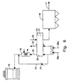
- FIGs 6 and 7 illustrate a different approach for passing excess air through the air preheater to provide additional cooling of the flue gas.
- the primary combustion air is fed to the coal pulverizer and serves to dry and transport the pulverized coal. Since excessively high temperatures of the coal-air mixture may result in a spontaneous combustion inside the pulverizers, the temperature of the primary combustion air to the pulverizers must be controlled. This typically involves bypassing as much as 40 or 50% of the primary air around the air heater. The bypassed air is used to control or temper the air temperature entering the pulverizers.
- Various coals have various recommended temperature limits which can range from about 77°C (170°F) up to 120°C (248°F).
- Figures 6 and 7 illustrate the secondary air 26a and the primary air 26b being forced through the air side 28 of the air preheater 28 of the air preheater 14 with the primary air 30 being fed to the pulverizer 70.
- the bypass air is carried around the air preheater 14 by the duct 72 and then reintroduced into the heated primary air thereby tempering the temperature.
- a damper 74 or other flow control device is located in the bypass duct 72 to control the quantity of the bypass air.
- this reduces the quantity of tempering air and increases the temperature of the primary air to the pulverizers. Therefore, means are provided to restore the proper pulverizer temperature.
- this comprises heat exchanger 76 which cools down the primary air temperature such as by the use of condensate water. In this case, the heat exchanger 76 serves as a low level economizer.
- Figure 7 illustrates another cooling arrangement comprising the introduction of spray water 78 directly into the primary air stream to provide evaporative cooling.
- Figure 8 illustrates a further embodiment of the present invention including the cooling of the flue gas after it has passed through the air preheater but prior to the electrostatic precipitator. This may be used alone as a means of further cooling the flue gas down to a temperature appropriate for the precipitator or it may be used in conjunction with the use of excess air through the air preheater as previously discussed.
- the partially cooled flue gas 15 from the air preheater 14 is passed through a low temperature economizer heat exchange section 80 where the flue gas is further cooled by feedwater 82 from the steam turbine loop (not shown) to a temperature favorable for precipitator operation.
- the further cooled flue gas 17 then goes to the electrostatic precipitator 16 and the heated feedwater 84 goes to the boiler 12.
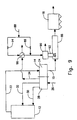
- Figure 9 shows an additional method for cooling the flue gas after the air preheater.
- the flue gas 15 from the air preheater 14 flows into and through a spray chamber 86 and then to the electrostatic precipitator 16.
- the spray chamber 86 which may be the flue gas duct itself, water droplets are injected into the flue gas stream. A portion of the sensible enthalpy of the flue gas is used to vaporize the water droplets thereby cooling the flue gas and increasing the humidity of the flue gas.
- the spray chamber 86 which may be the flue gas duct itself.
- a portion of the sensible enthalpy of the flue gas is used to vaporize the water droplets thereby cooling the flue gas and increasing the humidity of the flue gas.
- the latent heat of vaporization associated with approximately 10,000 Ibs/hr water spray will enable cooling of the flue gas by 10° F.
- the time for complete vaporization of the droplets is a function of several parameters including droplet size, flue gas temperature and flue gas moisture content. In particular, the vaporization time varies in proportion to the square of the droplet size. In the present invention, the droplet size is limited by any one of several means.
- the droplet size is limited by atomizing the water and then using a size separation device such as a cyclone, impactor, louver separator, mist elimination, electrostatic precipitator or filter to remove the oversize droplets.
- a size separation device such as a cyclone, impactor, louver separator, mist elimination, electrostatic precipitator or filter to remove the oversize droplets.
- the water 88 through valve 89 is sprayed into the separator generally designated at 90 and then sprayed at 92 into the flue gas.
- the critical droplet size is determined by the size that can be vaporized at or before the inlet to the electrostatic precipitator 16. This is controlled by the outlet temperature of the flue gas from the air preheater and the available residence time in the duct between the point of the water spray and the electrostatic precipitator. As an example, a nominal residence time of 1 second and a mean flue gas temperature of 110° C (230°F) will completely vaporize a 30 micron droplet.
- Figure 9 also illustrates a variation of this water spray cooling process wherein superheated water is used.
- the water 88 under pressure passes through valve 94 and is heated by the excess air 34 (or other heating medium) in the heat exchanger 96 to a temperature in excess of 100° C (212°F), preferably 120 to 130° C (248 to 266°F), before it is atomized and introduced into the spray chamber 86.
- the superheating of the spray water dramatically. decreases both the mean and the maximum droplet size.
- the corrosivity and fouling potential of the flue gas can vary the cooling requirements for the flue gas entering the particulate collection device. Therefore, it is desirable to anticipate these changes and to control the cooling accordingly.
- This is achieved by an integrated control scheme which includes the operating parameters of the air preheater, the boiler and the particulate collection device. The scheme allows the flue gas outlet temperature from the air preheater to be varied as needed for effective operation of the particulate collection device while maintaining the needed combustion air flow and temperatures as required for effective operation of the boiler.
- the various inputs which may be selected for such a control system include a flue gas analysis from continuous emission monitors for such factors as SO 2 and O 2 levels, the flue gas temperature at the air preheater outlet, the secondary air flow rate, the fuel analysis, the opacity of the flue gas, the full range of boiler operation data and the electrostatic precipitator control data.
- the resulting output of the control system may include the control of the air preheater to (1) provide a variable amount or variable temperature of the cooling air to provide a desired outlet flue gas temperature profile to minimize the corrosion and fouling potential, (2) control the electrostatic precipitator operation such as the high voltage settings and the rapping frequency to minimize power requirements for a given emission level and (3) control the boiler operation to accept at least a portion of the excess heated air from the air preheater as combustion air to increase the boiler efficiency.
Landscapes
- Engineering & Computer Science (AREA)
- Mechanical Engineering (AREA)
- General Engineering & Computer Science (AREA)
- Chemical & Material Sciences (AREA)
- Combustion & Propulsion (AREA)
- Physics & Mathematics (AREA)
- Thermal Sciences (AREA)
- Air Supply (AREA)
- Chimneys And Flues (AREA)
- Organic Low-Molecular-Weight Compounds And Preparation Thereof (AREA)
- Paper (AREA)
- Hydrogen, Water And Hydrids (AREA)
- Devices For Medical Bathing And Washing (AREA)
- Massaging Devices (AREA)
- Control Of Turbines (AREA)
- Filling Or Discharging Of Gas Storage Vessels (AREA)
- Control Of Steam Boilers And Waste-Gas Boilers (AREA)
- Electrostatic Separation (AREA)
- Sorption Type Refrigeration Machines (AREA)
- Air Humidification (AREA)
Claims (11)
- Verfahren zum Betreiben eines Dampferzeugungssystems (12) mit einem Dampferzeuger, der einen Abgasstrom (22) erzeugt, einem Luftvorwärmer (14), der Wärme von dem Abgasstrom (22) auf den ankommenden Luftstrom (26) überträgt, um einen Warmluftstrom zu erzeugen, einer Partikelkontrollvorrichtung (16) zum Entfernen von Partikeln aus dem Abgasstrom (22) und einem Abgasskrubber (18), der der Partikelkontrollvorrichtung (16) nachfolgt, wobei das Verfahren die folgenden Schritte umfaßt:a) Durchleiten einer Luftmenge (26) durch den Luftvorwärmer (14), in dem die Luft (26) erwärmt wird, wobei die Luftmenge (26) so ausgewählt wird, daß eine erwünschte Abgastemperatur zum Betrieb der Partikelkontrollvorrichtung (16) bereitgestellt wird, und sie einen Verbrennungsluft umfassenden ersten Teil (30, 32) und einen überschüssige Luft umfassenden zweiten Teil (34) beinhaltet;b) Ableiten der Warmluftmenge (26) aus dem Luftvorwärmer (14);c) Leiten des ersten Teils (30, 32) von Warmluft zu dem Dampferzeuger (12) als Verbrennungsluft;d) Leiten des zweiten Teils (34) von Warmluft um den Dampferzeuger (12) herum als überschüssige Luft; unde) Übertragen von Wärme aus der überschüssigen Warmluft (34) auf das aus dem Gasskrubber (18) ausgestoßene Abgas (19), um das ausgestoßene Abgas (19) wiederzuerwärmen.
- Verfahren nach Anspruch 1, wobei der Schritt des Übertragens von Wärme aus der überschüssigen Warmluft (34) auf das Abgas (18) den Schritt des Mixens der überschüssigen Warmluft (34) mit dem Abgas (18) umfaßt.
- Verfahren nach Anspruch 1, wobei das Dampferzeugungssystems außerdem einen Abgasskrubber (18) umfaßt, der der Partikelkontrollvorrichtung (16) nachfolgt und wobei Wärme von der überschüssigen Warmluft (34) auf das Abgas (19), das aus dem Gasskrubber (18) ausgestoßen wird, Übertragen wird, um das ausgestoßene Abgas (19) wiederzuerwärmen.
- Verfahren nach Anspruch 3, wobei der Schritt des Übertragens von Wärme aus der überschüssigen Warmluft (34) auf das Abgas den Schritt des Mixens der überschüssigen Warmluft (34) mit dem Abgas umfaßt.
- Verfahren nach Anspruch 1, wobei die Partikelkontrollvorrichtung (16) ein elektrostatischer Abscheider ist, der Komponenten umfaßt, die ein Erwärmen erfordern, und außerdem mit dem Schritt des Erwärmens der Komponenten mit der überschüssigen Warmluft (34).
- Verfahren nach Anspruch 5, wobei die Komponenten Fülltrichter und Isolatoren umfassen.
- Verfahren nach Anspruch 1, wobei der Luftvorwärmer, der Wärme aus dem Abgasstrom auf den ankommenden Luftstrom überträgt, einen Warmluftstrom und einen teilweise gekühlten Abgasstrom erzeugt, und außerdem mit dem Schritt des weiteren Kühlens des teilweise gekühlten Abgasstroms auf eine erwünschte Temperatur zum Betrieb der Partikelkontrollvorrichtung.
- Verfahren nach Anspruch 7, wobei der Schritt des weiteren Kühlens des teilweise gekühlten Abgasstroms den Schritt des Besprühens des teilweise gekühlten Abgasstroms mit Wassertropfen umfaßt.
- Verfahren nach Anspruch 7, wobei der Schritt des Besprühens mit Wassertropfen den Schritt des Zerstäubens von Wasser und des Entfernens übergroßer Tropfen umfaßt.
- Verfahren nach Anspruch 7, wobei die Tropfen überhitztes Wasser enthalten.
- Verfahren nach Anspruch 6, wobei das Dampferzeugungssystem außerdem einen Speisewasserstrom beinhaltet und der Schritt des weiteren Kühlens des teilweise gekühlten Abgasstroms den Schritt des Weiterleitens des teilweise gekühlten Abgasstroms in Wärmeaustauschkontakt mit dem Speisewasserstrom umfaßt, wobei der Speisewasserstrom erwärmt wird und der teilweise gekühlte Abgasstrom weiter auf eine zum Betrieb der Partikelkontrollvorrichtung gewünschte Temperatur abgekühlt wird.
Applications Claiming Priority (3)
| Application Number | Priority Date | Filing Date | Title |
|---|---|---|---|
| US09/069,405 US6089023A (en) | 1998-04-29 | 1998-04-29 | Steam generator system operation |
| US69405 | 1998-04-29 | ||
| PCT/US1999/009237 WO1999056063A1 (en) | 1998-04-29 | 1999-04-28 | Steam generator system operation |
Publications (2)
| Publication Number | Publication Date |
|---|---|
| EP1075627A1 EP1075627A1 (de) | 2001-02-14 |
| EP1075627B1 true EP1075627B1 (de) | 2001-12-12 |
Family
ID=22088768
Family Applications (1)
| Application Number | Title | Priority Date | Filing Date |
|---|---|---|---|
| EP99920121A Expired - Lifetime EP1075627B1 (de) | 1998-04-29 | 1999-04-28 | Dampferzeuger betriebsverfahren |
Country Status (20)
| Country | Link |
|---|---|
| US (1) | US6089023A (de) |
| EP (1) | EP1075627B1 (de) |
| JP (1) | JP2002513131A (de) |
| KR (1) | KR20010043069A (de) |
| CN (1) | CN1298480A (de) |
| AT (1) | ATE210801T1 (de) |
| AU (1) | AU755128B2 (de) |
| BR (1) | BR9910081A (de) |
| CA (1) | CA2323693A1 (de) |
| CZ (1) | CZ20004013A3 (de) |
| DE (1) | DE69900606T2 (de) |
| DK (1) | DK1075627T3 (de) |
| ES (1) | ES2169951T3 (de) |
| HU (1) | HUP0102246A3 (de) |
| ID (1) | ID27042A (de) |
| PL (1) | PL343675A1 (de) |
| SK (1) | SK16292000A3 (de) |
| TW (1) | TW396260B (de) |
| WO (1) | WO1999056063A1 (de) |
| ZA (1) | ZA200004474B (de) |
Families Citing this family (24)
| Publication number | Priority date | Publication date | Assignee | Title |
|---|---|---|---|---|
| DE19924593A1 (de) * | 1999-05-28 | 2000-11-30 | Abb Patent Gmbh | Verfahren zum Betrieb eines Dampfkraftwerkes |
| US7410611B2 (en) | 2001-01-31 | 2008-08-12 | Dennis L. Salbilla | In-line method and apparatus to prevent fouling of heat exchangers |
| US20040175302A1 (en) * | 2003-03-07 | 2004-09-09 | Alstom (Switzerland) Ltd | Preparation of sorbent for SO2 Scrubber system |
| US6946011B2 (en) * | 2003-03-18 | 2005-09-20 | The Babcock & Wilcox Company | Intermittent mixer with low pressure drop |
| US8015724B2 (en) * | 2004-04-23 | 2011-09-13 | Panasonic Electric Works Co., Ltd. | Heating blower with electrostatic atomizing device |
| US7475544B2 (en) * | 2004-11-02 | 2009-01-13 | Counterman Wayne S | Efficiency improvement for a utility steam generator with a regenerative air preheater |
| EP2108087A4 (de) * | 2007-02-01 | 2017-08-09 | Fluor Technologies Corporation | Umgebungsluftverdampfer |
| US8807991B2 (en) * | 2007-07-10 | 2014-08-19 | Babcock & Wilcox Power Generation Group, Inc. | Oxy-fuel combustion oxidant heater internal arrangement |
| US20100251975A1 (en) * | 2009-04-01 | 2010-10-07 | Alstom Technology Ltd | Economical use of air preheat |
| US8387545B2 (en) * | 2009-07-17 | 2013-03-05 | Conocophillips Company | Water recovery from flue gas in steam-assisted production |
| US9598742B2 (en) * | 2009-09-25 | 2017-03-21 | Arvos Inc. | Exhaust processing and heat recovery system |
| KR101399962B1 (ko) * | 2012-02-03 | 2014-06-27 | 삼성중공업 주식회사 | 풍력 발전기용 나셀 및 이를 구비한 풍력 발전기 |
| DE102013001440A1 (de) * | 2013-01-29 | 2014-07-31 | Rwe Power Aktiengesellschaft | Verfahren zur Regelung der Rauchgastemperatur an einem mit fossilen Brennstoffen gefeuerten Dampferzeuger |
| CH710092A1 (de) * | 2014-09-10 | 2016-03-15 | Robert Stucki | Verfahren zur raschen Abkühlung von Abgasen und Einspritzkühlvorrichtung. |
| US10267517B2 (en) * | 2016-07-08 | 2019-04-23 | Arvos Ljungstrom Llc | Method and system for improving boiler effectiveness |
| GB2566911A (en) * | 2016-07-08 | 2019-03-27 | Arvos Ljungstrom Llc | Method and system for improving boiler effectiveness |
| CN107013933B (zh) * | 2017-05-24 | 2023-04-07 | 南京博沃科技发展有限公司 | 一种管式空气预热器防低温结露及堵灰的方法及系统 |
| CN107388270A (zh) * | 2017-08-09 | 2017-11-24 | 胜利油田华滨实业有限公司石油机械滨州分公司 | 湿蒸汽发生器对流段自动吹灰系统 |
| CN109681905A (zh) * | 2018-11-26 | 2019-04-26 | 浙江浙能技术研究院有限公司 | 一种净烟气再热系统 |
| CN111412451A (zh) * | 2019-01-11 | 2020-07-14 | 中国电力工程顾问集团华北电力设计院有限公司 | 电站锅炉冷风加热及烟气余热综合利用系统 |
| CN110631040A (zh) * | 2019-10-18 | 2019-12-31 | 河北冀研能源科学技术研究院有限公司 | 一种高效节能烟气冷凝再热消白烟系统 |
| DE102020106773A1 (de) | 2020-03-12 | 2021-09-16 | Kutzner + Weber Gmbh | Vorrichtung zum Reinigen von Abgasen aus einer Feuerstelle |
| CN111442256A (zh) * | 2020-04-29 | 2020-07-24 | 北京慧峰仁和科技股份有限公司 | 利用旁路烟气加热一次风、给水及循环水的系统及方法 |
| CN117677797A (zh) * | 2021-02-12 | 2024-03-08 | 傲华容客有限责任公司 | 用于空气预热器装置的温度控制系统 |
Family Cites Families (12)
| Publication number | Priority date | Publication date | Assignee | Title |
|---|---|---|---|---|
| GB772685A (en) * | 1955-01-10 | 1957-04-17 | Air Preiieater Corp | Improvements in heat exchangers |
| US3726239A (en) * | 1971-12-29 | 1973-04-10 | Combustion Eng | Method and apparatus useful in combustion gas purification |
| US4090455A (en) * | 1977-04-04 | 1978-05-23 | Combustion Engineering, Inc. | Boiler start-up air heater |
| US4205630A (en) * | 1978-11-15 | 1980-06-03 | Combustion Engineering, Inc. | Steam air preheater for maintaining the flue gas temperature entering dust collection equipment |
| FR2572952B1 (fr) * | 1984-11-14 | 1987-02-06 | Kaiser Victor | Procede et installation de purification des fumees |
| JPS6245357A (ja) * | 1985-08-22 | 1987-02-27 | Mitsubishi Heavy Ind Ltd | 電気集塵装置の捕集性能変動の抑制方法 |
| FR2592812B1 (fr) * | 1986-01-14 | 1990-05-04 | Sobea | Procede pour la reduction de la teneur en polluants acides contenus dans des fumees et dispositif pour sa mise en oeuvre |
| US5203267A (en) * | 1991-01-22 | 1993-04-20 | New Clear Energy, Inc. | Method and apparatus for disposing of waste material |
| IL101377A (en) * | 1992-03-26 | 1996-05-14 | Israel Military Ind | Method and installation for the destruction of noxious materials |
| US5333558A (en) * | 1992-12-07 | 1994-08-02 | Svedala Industries, Inc. | Method of capturing and fixing volatile metal and metal oxides in an incineration process |
| DE4327476C2 (de) * | 1993-08-16 | 1997-04-03 | Steinmueller Gmbh L & C | Verfahren zum Betrieb eines mit fossilen Brennstoffen gefeuerten Dampferzeugers und Dampferzeugungsanlage |
| US5553555A (en) * | 1994-04-28 | 1996-09-10 | Dasibi Environmental Corporation | System and method for flue gas purification for thermal power units |
-
1998
- 1998-04-29 US US09/069,405 patent/US6089023A/en not_active Expired - Lifetime
-
1999
- 1999-04-28 WO PCT/US1999/009237 patent/WO1999056063A1/en not_active Ceased
- 1999-04-28 CA CA002323693A patent/CA2323693A1/en not_active Abandoned
- 1999-04-28 CZ CZ20004013A patent/CZ20004013A3/cs unknown
- 1999-04-28 AU AU37694/99A patent/AU755128B2/en not_active Ceased
- 1999-04-28 PL PL99343675A patent/PL343675A1/xx unknown
- 1999-04-28 EP EP99920121A patent/EP1075627B1/de not_active Expired - Lifetime
- 1999-04-28 SK SK1629-2000A patent/SK16292000A3/sk unknown
- 1999-04-28 ID IDW20002428A patent/ID27042A/id unknown
- 1999-04-28 ES ES99920121T patent/ES2169951T3/es not_active Expired - Lifetime
- 1999-04-28 KR KR1020007011949A patent/KR20010043069A/ko not_active Ceased
- 1999-04-28 DK DK99920121T patent/DK1075627T3/da active
- 1999-04-28 BR BR9910081-9A patent/BR9910081A/pt not_active Application Discontinuation
- 1999-04-28 DE DE69900606T patent/DE69900606T2/de not_active Expired - Fee Related
- 1999-04-28 HU HU0102246A patent/HUP0102246A3/hu unknown
- 1999-04-28 AT AT99920121T patent/ATE210801T1/de not_active IP Right Cessation
- 1999-04-28 JP JP2000546181A patent/JP2002513131A/ja active Pending
- 1999-04-28 CN CN99805610A patent/CN1298480A/zh active Pending
- 1999-07-03 TW TW088106945A patent/TW396260B/zh not_active IP Right Cessation
-
2000
- 2000-08-29 ZA ZA200004474A patent/ZA200004474B/xx unknown
Also Published As
| Publication number | Publication date |
|---|---|
| EP1075627A1 (de) | 2001-02-14 |
| KR20010043069A (ko) | 2001-05-25 |
| DK1075627T3 (da) | 2002-04-15 |
| PL343675A1 (en) | 2001-08-27 |
| ID27042A (id) | 2001-02-22 |
| US6089023A (en) | 2000-07-18 |
| WO1999056063A1 (en) | 1999-11-04 |
| DE69900606D1 (de) | 2002-01-24 |
| TW396260B (en) | 2000-07-01 |
| ZA200004474B (en) | 2001-07-25 |
| ATE210801T1 (de) | 2001-12-15 |
| DE69900606T2 (de) | 2002-09-19 |
| CN1298480A (zh) | 2001-06-06 |
| BR9910081A (pt) | 2000-12-26 |
| SK16292000A3 (sk) | 2001-07-10 |
| CA2323693A1 (en) | 1999-11-04 |
| CZ20004013A3 (cs) | 2001-12-12 |
| HUP0102246A3 (en) | 2001-12-28 |
| AU755128B2 (en) | 2002-12-05 |
| JP2002513131A (ja) | 2002-05-08 |
| ES2169951T3 (es) | 2002-07-16 |
| AU3769499A (en) | 1999-11-16 |
| HUP0102246A2 (hu) | 2001-10-28 |
Similar Documents
| Publication | Publication Date | Title |
|---|---|---|
| US6089023A (en) | Steam generator system operation | |
| US4223529A (en) | Combined cycle power plant with pressurized fluidized bed combustor | |
| EP0602795B1 (de) | Fliessbett-Verbrennungssystem und Fliessbett-Verbrennungsverfahren | |
| CA1128823A (en) | Steam air preheater for maintaining the flue gas temperature entering dust collection equipment | |
| RU1838635C (ru) | Способ производства электрической и тепловой энергии | |
| US20090272113A1 (en) | Heat recovery equipment | |
| KR20190026783A (ko) | 보일러 효율성을 향상시키기 위한 방법 및 시스템 | |
| JPH08502345A (ja) | 電気的なエネルギを生ぜしめるための蒸気動力装置 | |
| US4571949A (en) | Cogeneration and sludge drying system | |
| US4509583A (en) | Apparatus for regenerative flue gas heat exchanger | |
| CN1211308A (zh) | 锅炉 | |
| AU2011373344B2 (en) | Fluidized bed drying facility | |
| JP3093775B2 (ja) | ガスタービン・蒸気タービン複合サイクル方式と該方式の実施に使用する発電設備 | |
| US5435123A (en) | Environmentally acceptable electric energy generation process and plant | |
| US4424765A (en) | Steam generator having external fluidized bed combustion means | |
| JP5634101B2 (ja) | 流動層乾燥設備 | |
| US20060090468A1 (en) | Efficiency improvement for a utility steam generator with a regenerative air preheater | |
| EP3203150B1 (de) | Kraftwerk und verfahren zur erhöhung des wirkungsgrades des kraftwerks | |
| JPH08296835A (ja) | 微粉炭焚火力発電システム | |
| MXPA00010261A (en) | Steam generator system operation | |
| CN208312354U (zh) | 一种二次再热发电系统 | |
| USH5H (en) | Pressure-fired fluidized-bed boiler installation | |
| Bullinger et al. | Coal drying improves performance and reduces emissions | |
| DE102004050465B3 (de) | Verfahren zur Erwärmung und/oder Verdampfung eines Fluids | |
| JP2007263505A (ja) | 石炭焚きボイラの制御装置 |
Legal Events
| Date | Code | Title | Description |
|---|---|---|---|
| PUAI | Public reference made under article 153(3) epc to a published international application that has entered the european phase |
Free format text: ORIGINAL CODE: 0009012 |
|
| 17P | Request for examination filed |
Effective date: 20000821 |
|
| AK | Designated contracting states |
Kind code of ref document: A1 Designated state(s): AT BE CH DE DK ES FR GB IT LI SE |
|
| RIN1 | Information on inventor provided before grant (corrected) |
Inventor name: SRINIVASACHAR, SRIVATS Inventor name: SEEBALD, JAMES, D. Inventor name: RINI, MICHAEL, J. Inventor name: PORLE, KJELL, E., G. Inventor name: PINNEKAMP, FRIEDRICH Inventor name: PALKES, MARK Inventor name: COUNTERMAN, WAYNE S. Inventor name: ANDERSON, DAVID, K. |
|
| GRAG | Despatch of communication of intention to grant |
Free format text: ORIGINAL CODE: EPIDOS AGRA |
|
| 17Q | First examination report despatched |
Effective date: 20010418 |
|
| RAP1 | Party data changed (applicant data changed or rights of an application transferred) |
Owner name: ALSTOM POWER INC. |
|
| GRAG | Despatch of communication of intention to grant |
Free format text: ORIGINAL CODE: EPIDOS AGRA |
|
| GRAH | Despatch of communication of intention to grant a patent |
Free format text: ORIGINAL CODE: EPIDOS IGRA |
|
| GRAH | Despatch of communication of intention to grant a patent |
Free format text: ORIGINAL CODE: EPIDOS IGRA |
|
| GRAA | (expected) grant |
Free format text: ORIGINAL CODE: 0009210 |
|
| AK | Designated contracting states |
Kind code of ref document: B1 Designated state(s): AT BE CH DE DK ES FR GB IT LI SE |
|
| REF | Corresponds to: |
Ref document number: 210801 Country of ref document: AT Date of ref document: 20011215 Kind code of ref document: T |
|
| REG | Reference to a national code |
Ref country code: CH Ref legal event code: EP |
|
| REG | Reference to a national code |
Ref country code: GB Ref legal event code: IF02 |
|
| REF | Corresponds to: |
Ref document number: 69900606 Country of ref document: DE Date of ref document: 20020124 |
|
| PGFP | Annual fee paid to national office [announced via postgrant information from national office to epo] |
Ref country code: FR Payment date: 20020328 Year of fee payment: 4 |
|
| REG | Reference to a national code |
Ref country code: CH Ref legal event code: NV Representative=s name: ISLER & PEDRAZZINI AG |
|
| PGFP | Annual fee paid to national office [announced via postgrant information from national office to epo] |
Ref country code: SE Payment date: 20020402 Year of fee payment: 4 |
|
| PGFP | Annual fee paid to national office [announced via postgrant information from national office to epo] |
Ref country code: DK Payment date: 20020403 Year of fee payment: 4 |
|
| PGFP | Annual fee paid to national office [announced via postgrant information from national office to epo] |
Ref country code: AT Payment date: 20020409 Year of fee payment: 4 |
|
| REG | Reference to a national code |
Ref country code: DK Ref legal event code: T3 |
|
| PGFP | Annual fee paid to national office [announced via postgrant information from national office to epo] |
Ref country code: ES Payment date: 20020423 Year of fee payment: 4 |
|
| PGFP | Annual fee paid to national office [announced via postgrant information from national office to epo] |
Ref country code: BE Payment date: 20020508 Year of fee payment: 4 |
|
| ET | Fr: translation filed | ||
| REG | Reference to a national code |
Ref country code: ES Ref legal event code: FG2A Ref document number: 2169951 Country of ref document: ES Kind code of ref document: T3 |
|
| PLBE | No opposition filed within time limit |
Free format text: ORIGINAL CODE: 0009261 |
|
| STAA | Information on the status of an ep patent application or granted ep patent |
Free format text: STATUS: NO OPPOSITION FILED WITHIN TIME LIMIT |
|
| 26N | No opposition filed | ||
| PG25 | Lapsed in a contracting state [announced via postgrant information from national office to epo] |
Ref country code: GB Free format text: LAPSE BECAUSE OF NON-PAYMENT OF DUE FEES Effective date: 20030428 Ref country code: AT Free format text: LAPSE BECAUSE OF NON-PAYMENT OF DUE FEES Effective date: 20030428 |
|
| PG25 | Lapsed in a contracting state [announced via postgrant information from national office to epo] |
Ref country code: SE Free format text: LAPSE BECAUSE OF NON-PAYMENT OF DUE FEES Effective date: 20030429 Ref country code: ES Free format text: LAPSE BECAUSE OF NON-PAYMENT OF DUE FEES Effective date: 20030429 |
|
| PG25 | Lapsed in a contracting state [announced via postgrant information from national office to epo] |
Ref country code: LI Free format text: LAPSE BECAUSE OF NON-PAYMENT OF DUE FEES Effective date: 20030430 Ref country code: DK Free format text: LAPSE BECAUSE OF NON-PAYMENT OF DUE FEES Effective date: 20030430 Ref country code: CH Free format text: LAPSE BECAUSE OF NON-PAYMENT OF DUE FEES Effective date: 20030430 Ref country code: BE Free format text: LAPSE BECAUSE OF NON-PAYMENT OF DUE FEES Effective date: 20030430 |
|
| BERE | Be: lapsed |
Owner name: *ALSTOM POWER INC. Effective date: 20030430 |
|
| EUG | Se: european patent has lapsed | ||
| REG | Reference to a national code |
Ref country code: DK Ref legal event code: EBP |
|
| REG | Reference to a national code |
Ref country code: CH Ref legal event code: PL |
|
| GBPC | Gb: european patent ceased through non-payment of renewal fee | ||
| PG25 | Lapsed in a contracting state [announced via postgrant information from national office to epo] |
Ref country code: FR Free format text: LAPSE BECAUSE OF NON-PAYMENT OF DUE FEES Effective date: 20031231 |
|
| REG | Reference to a national code |
Ref country code: FR Ref legal event code: ST |
|
| REG | Reference to a national code |
Ref country code: ES Ref legal event code: FD2A Effective date: 20030429 |
|
| PG25 | Lapsed in a contracting state [announced via postgrant information from national office to epo] |
Ref country code: IT Free format text: LAPSE BECAUSE OF NON-PAYMENT OF DUE FEES Effective date: 20050428 |
|
| PGFP | Annual fee paid to national office [announced via postgrant information from national office to epo] |
Ref country code: DE Payment date: 20060320 Year of fee payment: 8 |
|
| PG25 | Lapsed in a contracting state [announced via postgrant information from national office to epo] |
Ref country code: DE Free format text: LAPSE BECAUSE OF NON-PAYMENT OF DUE FEES Effective date: 20071101 |