EP1074718A2 - Verfahren zur Plausibilitätsprüfung von Motorgrössen und Sensorgrössen unter Verwendung einer stetigen Lambda-Sonde - Google Patents
Verfahren zur Plausibilitätsprüfung von Motorgrössen und Sensorgrössen unter Verwendung einer stetigen Lambda-Sonde Download PDFInfo
- Publication number
- EP1074718A2 EP1074718A2 EP00115537A EP00115537A EP1074718A2 EP 1074718 A2 EP1074718 A2 EP 1074718A2 EP 00115537 A EP00115537 A EP 00115537A EP 00115537 A EP00115537 A EP 00115537A EP 1074718 A2 EP1074718 A2 EP 1074718A2
- Authority
- EP
- European Patent Office
- Prior art keywords
- internal combustion
- combustion engine
- lambda probe
- lambda
- control value
- Prior art date
- Legal status (The legal status is an assumption and is not a legal conclusion. Google has not performed a legal analysis and makes no representation as to the accuracy of the status listed.)
- Granted
Links
Images
Classifications
-
- F—MECHANICAL ENGINEERING; LIGHTING; HEATING; WEAPONS; BLASTING
- F02—COMBUSTION ENGINES; HOT-GAS OR COMBUSTION-PRODUCT ENGINE PLANTS
- F02D—CONTROLLING COMBUSTION ENGINES
- F02D41/00—Electrical control of supply of combustible mixture or its constituents
- F02D41/02—Circuit arrangements for generating control signals
- F02D41/14—Introducing closed-loop corrections
- F02D41/1438—Introducing closed-loop corrections using means for determining characteristics of the combustion gases; Sensors therefor
- F02D41/1493—Details
- F02D41/1495—Detection of abnormalities in the air/fuel ratio feedback system
-
- F—MECHANICAL ENGINEERING; LIGHTING; HEATING; WEAPONS; BLASTING
- F02—COMBUSTION ENGINES; HOT-GAS OR COMBUSTION-PRODUCT ENGINE PLANTS
- F02D—CONTROLLING COMBUSTION ENGINES
- F02D41/00—Electrical control of supply of combustible mixture or its constituents
- F02D41/0025—Controlling engines characterised by use of non-liquid fuels, pluralities of fuels, or non-fuel substances added to the combustible mixtures
- F02D41/0047—Controlling exhaust gas recirculation [EGR]
-
- F—MECHANICAL ENGINEERING; LIGHTING; HEATING; WEAPONS; BLASTING
- F02—COMBUSTION ENGINES; HOT-GAS OR COMBUSTION-PRODUCT ENGINE PLANTS
- F02M—SUPPLYING COMBUSTION ENGINES IN GENERAL WITH COMBUSTIBLE MIXTURES OR CONSTITUENTS THEREOF
- F02M26/00—Engine-pertinent apparatus for adding exhaust gases to combustion-air, main fuel or fuel-air mixture, e.g. by exhaust gas recirculation [EGR] systems
- F02M26/13—Arrangement or layout of EGR passages, e.g. in relation to specific engine parts or for incorporation of accessories
- F02M26/14—Arrangement or layout of EGR passages, e.g. in relation to specific engine parts or for incorporation of accessories in relation to the exhaust system
- F02M26/15—Arrangement or layout of EGR passages, e.g. in relation to specific engine parts or for incorporation of accessories in relation to the exhaust system in relation to engine exhaust purifying apparatus
Definitions
- the invention relates to a method for monitoring the function of an exhaust gas duct an internal combustion engine arranged lambda probe with the in the preamble of Claim 1 mentioned features.
- Exhaust channel at least one lambda probe, in particular a broadband lambda probe, to arrange.
- an oxygen concentration in an exhaust gas can be detected and a conclusion on the ratio of an oxygen fraction to a fuel fraction take place in the air-fuel mixture supplied to the combustion process.
- Broadband lambda probes enable measurement of lambda in a range of about 0.7 to ⁇ .
- the lambda probe Measurement signal for controlling the air-fuel mixture according to the given Requirements for the internal combustion engine used (lambda control).
- the measurement signal is read into an engine control unit and serves as the basis for Measures that, for example, regulate an injection system or intake air include.
- Lambda probes of this type are usually also used to monitor in addition the exhaust duct arranged catalysts. Redox reactions take place on the catalysts instead, which leads to a conversion of pollutants contained in the exhaust gas into less environmentally relevant Lead reaction products.
- the operating mode of the internal combustion engine is based on the Measurement signal of the lambda probe regulated.
- the measurement signal provided is faulty due to a defect in the lambda probe, this can on the one hand result in the setting of a lead to low-consumption operating mode, and on the other hand one can possibly Reduction of pollutant emissions by means of the catalysts no longer in the necessary dimensions are granted.
- the invention has for its object to provide a method that a Functional monitoring of the lambda probe allowed and thus possible rectification Defects in the lambda probe enabled.
- a predeterminable number of Control values first of all to a correlation calculation, in particular a cross-correlation subject.
- the correlation calculation then delivers a correlated control value.
- a maintenance signal is generated in a preferred manner (on-board diagnosis). Based on the Maintenance signals can then provide appropriate information to a vehicle driver the maintenance personnel must carry out a necessary maintenance measure be proposed.
- the diagnosis period is such choose that he immediately a load change or a change in speed of the Internal combustion engine connects, since there are particularly significant measurement signals. It is therefore not necessary to use special functions for monitoring the lambda probe Let signal patterns run and thus the normal operation of the Interrupt internal combustion engine.
- Parameters such as one, flow into the model for the internal combustion engine Intake air mass, a fuel mass and the speed.
- Intake air mass a fuel mass and the speed.
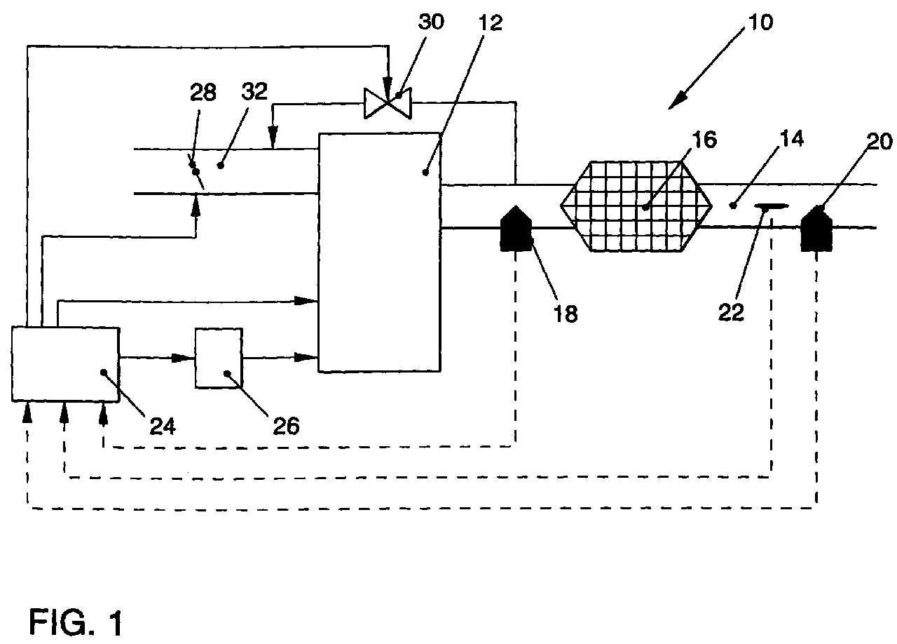
- FIG. 10 An arrangement 10 of an internal combustion engine 12 is shown in FIG a catalytic converter 16 arranged in an exhaust gas duct 14 and two lambda probes 18, 20 includes.
- a temperature sensor 22 is additionally arranged downstream of the catalytic converter 16, with which an exhaust gas temperature can be detected.
- the catalyst 16 serves one Conversion of pollutants contained in the exhaust gas of the internal combustion engine 12.
- a ratio of an oxygen fraction to a fuel fraction in one to be burned Air-fuel mixture provides a lambda value.
- the lambda probe 18 can be an oxygen concentration immediately behind the internal combustion engine 12 detect, the oxygen concentration clearly assigned to a lambda value can be.
- a conversion rate of the catalytic converter 16 can be determined using a monitor the signal provided by the lambda probe 20 in a known manner.
- the Lambda value is continuously recorded according to the exemplary embodiment, that is, the Lambda probes 18, 20 are so-called broadband lambda probes.
- a range of measurements for Broadband lambda probes range from approximately 0.7 to ⁇ . How it works such probes is known, so that in the context of the present description should not be discussed in more detail.
- the measurement signals detected by the sensors 18, 20, 22 are fed into an engine control unit 24 read, evaluated and to control an operating mode of the Internal combustion engine 12 used.
- the internal combustion engine 12 is a means assigned, for example, an injection system 26 or an exhaust gas recirculation include.
- the exhaust gas recirculation can reduce the volume flow intake air by means of a throttle valve 28 and by simultaneous supply low-oxygen exhaust gas take place via an exhaust gas reflux valve 30. In this way it is Oxygen content of a via an intake pipe 32 of the internal combustion engine 12 provided intake air mass can be specified.
- Exhaust gas turbochargers of supercharged engines have at least one lambda probe behind them Turbine in the exhaust gas.
- FIG. 2 shows a block diagram for function monitoring of the lambda probes 18, 20.
- a step S1 in addition to that by the lambda probes 18, 20 Provided measurement signal determines a target signal.
- a model for the internal combustion engine is used for this 12.
- the model includes parameters such as the intake air mass, a injected fuel mass or a speed of the internal combustion engine 12. It is also conceivable to use other sizes, for example in the engine control unit 24 are provided to be used to optimize the model.
- the operating mode of the internal combustion engine 12 must be used for function monitoring can not be controlled according to a signal pattern, but any Operating points can be used for monitoring. It has proven to be advantageous a diagnosis period immediately after a load change or a change in the Let the speed of the internal combustion engine 12 begin.
- a ratio of the measurement signal to the target signal provides a control value (step S2).
- the control value KW or the correlated control value KW k is then compared in a step S3 with a predefinable limit value GW.
- the limit value GW can also be determined using the model for the internal combustion engine 12. If the control value KW or the correlated control value KW k is below the limit value GW, a new measuring cycle of the function monitoring can follow, starting with step S1. However, if the control value KW or the correlated control value KW k exceeds the limit value GW, a maintenance signal is generated in a step S4. The maintenance signal then serves, for example in an on-board diagnosis, to inform a vehicle driver. Furthermore, the maintenance signal can be used to provide the maintenance personnel with appropriate instructions.
Landscapes
- Engineering & Computer Science (AREA)
- Chemical & Material Sciences (AREA)
- Combustion & Propulsion (AREA)
- Mechanical Engineering (AREA)
- General Engineering & Computer Science (AREA)
- Combined Controls Of Internal Combustion Engines (AREA)
- Testing Of Engines (AREA)
- Measurement Of Length, Angles, Or The Like Using Electric Or Magnetic Means (AREA)
- Apparatus For Radiation Diagnosis (AREA)
- Measurement Of The Respiration, Hearing Ability, Form, And Blood Characteristics Of Living Organisms (AREA)
Abstract
Description
- Figur 1
- eine Anordnung von Lambda-Sonden in einem Abgaskanal einer Verbrennungskraftmaschine und
- Figur 2
- ein Blockschaltbild zur Funktionsüberwachung der Lambda-Sonden.
Claims (6)
- Verfahren zur Funktionsüberwachung wenigstens einer in einem Abgaskanal einer Verbrennungskraftmaschine angeordneten Lambda-Sonde, insbesondere einer Breitband-Lambda-Sonde, dadurch gekennzeichnet, daß(a) innerhalb eines vorgebbaren Diagnosezeitraums ein Meßsignal der Lambda-Sonde (18, 20) erfaßt wird,(b) anhand eines Modells für die Verbrennungskraftmaschine (12) ein Sollsignal der Lambda-Sonde (18, 20) ermittelt wird und(c) ein Verhältnis des Meßsignals zum Sollsignal einen Kontrollwert (KW) liefert und der Kontrollwert (KW) mit einem vorgebbaren Grenzwert (GW) verglichen wird.
- Verfahren nach Anspruch 1, dadurch gekennzeichnet, daß eine vorgebbare Anzahl der Kontrollwerte (KW) zunächst einer Korrelationsrechnung, insbesondere einer Kreuzkorrelation, unterworfen werden und einen korrelierten Kontrollwert (KWk) liefern.
- Verfahren nach den Ansprüchen 1 oder 2, dadurch gekennzeichnet, daß beim Überschreiten des Kontrollwertes (KW) oder des korrelierten Kontrollwertes (KWk) über den Grenzwert (GW) ein Wartungssignal erzeugt wird.
- Verfahren nach einem der vorhergehenden Ansprüche, dadurch gekennzeichnet, daß der Diagnosezeitraum unmittelbar nach einem Lastwechsel oder einer Änderung der Drehzahl der Verbrennungskraftmaschine (12) beginnt.
- Verfahren nach einem der vorhergehenden Ansprüche, dadurch gekennzeichnet, daß das Modell für die Verbrennungskraftmaschine (12) Parameter, wie eine Ansaugluftmasse, eine eingespritzte Kraftstoffmasse und die Drehzahl, umfaßt.
- Verfahren nach einem der vorhergehenden Ansprüche, dadurch gekennzeichnet, daß der Grenzwert (GW) über das Modell für die Verbrennungskraftmaschine (12) festgelegt wird.
Applications Claiming Priority (2)
| Application Number | Priority Date | Filing Date | Title |
|---|---|---|---|
| DE19936355 | 1999-08-03 | ||
| DE19936355A DE19936355A1 (de) | 1999-08-03 | 1999-08-03 | Verfahren zur Plausibilitätsprüfung von Motorgrößen und Sensorgrößen unter Verwendung einer stetigen Lambda-Sonde |
Publications (3)
| Publication Number | Publication Date |
|---|---|
| EP1074718A2 true EP1074718A2 (de) | 2001-02-07 |
| EP1074718A3 EP1074718A3 (de) | 2001-09-26 |
| EP1074718B1 EP1074718B1 (de) | 2004-11-10 |
Family
ID=7916920
Family Applications (1)
| Application Number | Title | Priority Date | Filing Date |
|---|---|---|---|
| EP00115537A Expired - Lifetime EP1074718B1 (de) | 1999-08-03 | 2000-07-19 | Verfahren zur Plausibilitätsprüfung von Motorgrössen und Sensorgrössen unter Verwendung einer stetigen Lambda-Sonde |
Country Status (3)
| Country | Link |
|---|---|
| EP (1) | EP1074718B1 (de) |
| AT (1) | ATE282144T1 (de) |
| DE (2) | DE19936355A1 (de) |
Cited By (8)
| Publication number | Priority date | Publication date | Assignee | Title |
|---|---|---|---|---|
| DE102004033325B4 (de) * | 2003-07-10 | 2006-05-24 | Honda Motor Co., Ltd. | Diagnosevorrichtung für einen Abgas-Sensor |
| EP1746276A2 (de) | 2005-07-22 | 2007-01-24 | Robert Bosch Gmbh | Überwachung von Abgasgrenzwerten |
| WO2009011191A1 (en) * | 2007-07-19 | 2009-01-22 | Toyota Jidosha Kabushiki Kaisha | Abnormality detection device for internal combustion engine and air/fuel ratio control apparatus for internal combustion engine |
| WO2011018317A1 (de) | 2009-08-10 | 2011-02-17 | Robert Bosch Gmbh | Verfahren und vorrichtung zur dynamik-diagnose einer abgas-sonde |
| WO2013087262A1 (de) * | 2011-12-12 | 2013-06-20 | Robert Bosch Gmbh | Verfahren und vorrichtung zur dynamiküberwachung von gas-sensoren |
| WO2013110385A1 (de) * | 2012-01-25 | 2013-08-01 | Robert Bosch Gmbh | Verfahren und steuereinheit zur bestimmung einer totzeit eines abgassensors einer brennkraftmaschine |
| CN103967567A (zh) * | 2013-02-04 | 2014-08-06 | 罗伯特·博世有限公司 | 一种用于运行内燃机废气系统中进气量探测器装置的方法 |
| WO2022084067A1 (fr) * | 2020-10-23 | 2022-04-28 | Vitesco Technologies GmbH | Calculateur pour diagnostic d'encrassement d'une sonde pour vehicule |
Families Citing this family (7)
| Publication number | Priority date | Publication date | Assignee | Title |
|---|---|---|---|---|
| DE10029633A1 (de) * | 2000-04-07 | 2001-10-11 | Volkswagen Ag | Mehrflutige Abgasanlage eines Mehrzylindermotors und Verfahren zur Regelung eines Luft-Kraftstoff-Verhältnisses |
| DE10111586A1 (de) * | 2001-03-10 | 2002-09-12 | Volkswagen Ag | Verfahren zum Betrieb von Brennkraftmaschinen |
| DE10128969C1 (de) * | 2001-06-15 | 2002-12-12 | Audi Ag | Verfahren zur Diagnose einer Führungssonde |
| DE10250219A1 (de) * | 2002-10-23 | 2004-05-06 | Volkswagen Ag | Regler und Verfahren zur Regelung eines in einem Abgaskanal einer Verbrennungskraftmaschine angeordneten NOx-Sensors |
| DE10307342B4 (de) * | 2003-02-21 | 2005-08-11 | Volkswagen Ag | Vorrichtung und Verfahren zur modellbasierten On-Board-Diagnose |
| DE102005016075B4 (de) * | 2005-04-08 | 2007-04-12 | Audi Ag | Verfahren zur Diagnose einer dem Abgaskatalysator einer Brennkraftmaschine zugeordneten Lambdasonde |
| JP4816773B2 (ja) * | 2009-07-16 | 2011-11-16 | 株式会社デンソー | 排気成分濃度センサの応答性検出装置 |
Family Cites Families (6)
| Publication number | Priority date | Publication date | Assignee | Title |
|---|---|---|---|---|
| US5550762A (en) * | 1993-12-20 | 1996-08-27 | Doll; John A. | Diagnostic system for electronic automotive system |
| DE19612212B4 (de) * | 1995-03-31 | 2005-12-08 | Denso Corp., Kariya | Diagnosevorrichtung für einen Luft/Brennstoffverhältnis-Sensor |
| GB2301901B (en) * | 1995-06-05 | 1999-04-07 | Nippon Denso Co | Apparatus and method for diagnosing degradation or malfunction of oxygen sensor |
| JP3743577B2 (ja) * | 1995-09-25 | 2006-02-08 | 本田技研工業株式会社 | 内燃エンジンの空燃比制御装置 |
| DE19606652B4 (de) * | 1996-02-23 | 2004-02-12 | Robert Bosch Gmbh | Verfahren der Einstellung des Kraftstoff-Luftverhältnisses für eine Brennkraftmaschine mit nachgeschaltetem Katalysator |
| DE19844994C2 (de) * | 1998-09-30 | 2002-01-17 | Siemens Ag | Verfahren zur Diagnose einer stetigen Lambdasonde |
-
1999
- 1999-08-03 DE DE19936355A patent/DE19936355A1/de not_active Withdrawn
-
2000
- 2000-07-19 AT AT00115537T patent/ATE282144T1/de not_active IP Right Cessation
- 2000-07-19 DE DE50008573T patent/DE50008573D1/de not_active Expired - Fee Related
- 2000-07-19 EP EP00115537A patent/EP1074718B1/de not_active Expired - Lifetime
Cited By (22)
| Publication number | Priority date | Publication date | Assignee | Title |
|---|---|---|---|---|
| DE102004033325B4 (de) * | 2003-07-10 | 2006-05-24 | Honda Motor Co., Ltd. | Diagnosevorrichtung für einen Abgas-Sensor |
| EP1746276A2 (de) | 2005-07-22 | 2007-01-24 | Robert Bosch Gmbh | Überwachung von Abgasgrenzwerten |
| EP1746276A3 (de) * | 2005-07-22 | 2013-05-22 | Robert Bosch Gmbh | Überwachung von Abgasgrenzwerten |
| WO2009011191A1 (en) * | 2007-07-19 | 2009-01-22 | Toyota Jidosha Kabushiki Kaisha | Abnormality detection device for internal combustion engine and air/fuel ratio control apparatus for internal combustion engine |
| CN101755115A (zh) * | 2007-07-19 | 2010-06-23 | 丰田自动车株式会社 | 用于内燃机的异常检测装置及用于内燃机的空燃比控制设备 |
| US8050852B2 (en) | 2007-07-19 | 2011-11-01 | Toyota Jidosha Kabushiki Kaisha | Abnormality detection device for internal combustion engine and air/fuel ratio control apparatus for internal combustion engine |
| CN101755115B (zh) * | 2007-07-19 | 2013-04-10 | 丰田自动车株式会社 | 用于内燃机的异常检测装置及用于内燃机的空燃比控制设备 |
| US8646324B2 (en) | 2009-08-10 | 2014-02-11 | Robert Bosch Gmbh | Method and device for dynamically diagnosing an exhaust gas probe |
| WO2011018317A1 (de) | 2009-08-10 | 2011-02-17 | Robert Bosch Gmbh | Verfahren und vorrichtung zur dynamik-diagnose einer abgas-sonde |
| CN102472186A (zh) * | 2009-08-10 | 2012-05-23 | 罗伯特·博世有限公司 | 用于对废气探测仪进行动态诊断的方法和装置 |
| US20120222474A1 (en) * | 2009-08-10 | 2012-09-06 | Robert Bosch Gmbh | Method and device for dynamically diagnosing an exhaust gas probe |
| CN102472186B (zh) * | 2009-08-10 | 2015-06-17 | 罗伯特·博世有限公司 | 用于对废气探测仪进行动态诊断的方法和装置 |
| WO2013087262A1 (de) * | 2011-12-12 | 2013-06-20 | Robert Bosch Gmbh | Verfahren und vorrichtung zur dynamiküberwachung von gas-sensoren |
| US10060894B2 (en) | 2011-12-12 | 2018-08-28 | Robert Bosch Gmbh | Method and device for dynamic monitoring of gas sensors |
| WO2013110385A1 (de) * | 2012-01-25 | 2013-08-01 | Robert Bosch Gmbh | Verfahren und steuereinheit zur bestimmung einer totzeit eines abgassensors einer brennkraftmaschine |
| US9518893B2 (en) | 2012-01-25 | 2016-12-13 | Robert Bosch Gmbh | Method and control unit for determining a dead time of an exhaust gas sensor of an internal combustion engine |
| CN103967567A (zh) * | 2013-02-04 | 2014-08-06 | 罗伯特·博世有限公司 | 一种用于运行内燃机废气系统中进气量探测器装置的方法 |
| CN103967567B (zh) * | 2013-02-04 | 2018-03-30 | 罗伯特·博世有限公司 | 一种用于运行内燃机废气系统中进气量探测器装置的方法 |
| WO2022084067A1 (fr) * | 2020-10-23 | 2022-04-28 | Vitesco Technologies GmbH | Calculateur pour diagnostic d'encrassement d'une sonde pour vehicule |
| FR3115597A1 (fr) * | 2020-10-23 | 2022-04-29 | Vitesco Technologies | Calculateur pour diagnostic d’encrassement d’une sonde pour véhicule |
| CN116490676A (zh) * | 2020-10-23 | 2023-07-25 | 纬湃科技有限责任公司 | 用于载具的探测器堵塞诊断的计算机 |
| US12146430B2 (en) | 2020-10-23 | 2024-11-19 | Vitesco Technologies GmbH | Computer for diagnosing clogging of a probe for a vehicle |
Also Published As
| Publication number | Publication date |
|---|---|
| DE19936355A1 (de) | 2001-02-08 |
| EP1074718B1 (de) | 2004-11-10 |
| DE50008573D1 (de) | 2004-12-16 |
| EP1074718A3 (de) | 2001-09-26 |
| ATE282144T1 (de) | 2004-11-15 |
Similar Documents
| Publication | Publication Date | Title |
|---|---|---|
| EP3527810B1 (de) | Verfahren zum betrieb einer verbrennungskraftmaschine | |
| DE10227838B4 (de) | Katalysatorleistungsabbau-Erfassungsvorrichtung | |
| DE102008042549B4 (de) | Verfahren und Vorrichtung zur Diagnose einer Abgassonde | |
| EP1074718B1 (de) | Verfahren zur Plausibilitätsprüfung von Motorgrössen und Sensorgrössen unter Verwendung einer stetigen Lambda-Sonde | |
| DE10111586A1 (de) | Verfahren zum Betrieb von Brennkraftmaschinen | |
| DE102009055082A1 (de) | Verfahren zur Überwachung einer Schadstoff-Konvertierungsfähigkeit in einem Abgasnachbehandlungssystem | |
| EP2401485B1 (de) | Verfahren zum betrieb eines abgassystems | |
| DE102018104258A1 (de) | Technik zur Kraftstoffbestimmung | |
| DE10309422A1 (de) | Verfahren und Vorrichtung zur Kalibrierung eines NOx-Sensors | |
| DE102008042925B3 (de) | Verfahren zur Bestimmung der Cetanzahl CZ eines Kraftstoffes | |
| EP1200811B1 (de) | Verfahren zur zustandserfassung eines katalysatorsystems | |
| DE10234340B4 (de) | Verfahren zur Bestimmung des Beladungszustandes eines Partikelfilters einer Brennkraftmaschine | |
| DE102023210670B4 (de) | Verfahren zum Betreiben einer Antriebseinrichtung für ein Kraftfahrzeug, Antriebseinrichtung für ein Kraftfahrzeug sowie Computerprogrammprodukt | |
| EP1136670A2 (de) | Vorrichtung und Verfahren zur Funktionsüberwachung eines 3-Wege-Katalysators im Abgaskanal einer Verbrennungskraftmaschine | |
| DE102023205130B3 (de) | Verfahren zum Betreiben einer Antriebseinrichtung für ein Kraftfahrzeug, Antriebseinrichtung für ein Kraftfahrzeug sowie Computerprogrammprodukt | |
| EP1434049B1 (de) | Verfahren und Vorrichtung zur Überwachung des NOx-Signals eines NOx-Sensors | |
| DE19963936A1 (de) | Verfahren zum Betreiben einer Brennkraftmaschine insbesondere eines Kraftfahrzeugs | |
| DE102006026739A1 (de) | Verfahren und Vorrichtung zum Betreiben einer Brennkraftmaschine | |
| DE102022101084B3 (de) | Verfahren zum Betreiben einer Antriebseinrichtung für ein Kraftfahrzeug sowie entsprechende Antriebseinrichtung | |
| EP1331372B1 (de) | Verfahren und Vorrichtung zum abgasnormkonformen Betreiben von NOx-Speicherkatalysatoren und zur Alterungsdiagnose derselben | |
| DE102006002257B4 (de) | Verfahren und Vorrichtung zum Betreiben eines Abgaskatalysators einer Brennkraftmaschine | |
| DE102025118572B3 (de) | Verfahren zum Überwachen einer Schadstoffemission einer Antriebseinrichtung für ein Kraftfahrzeug, entsprechende Antriebseinrichtung für ein Kraftfahrzeug sowie Computerprogrammprodukt | |
| DE102024131374B3 (de) | Verfahren zum Betreiben einer Antriebseinrichtung für ein Kraftfahrzeug, entsprechende Antriebseinrichtung sowie Computerprogrammprodukt | |
| DE102025117179A1 (de) | Verfahren und Vorrichtung zur Vorhersage von Abgasemissionen einer Abgasnachbehandlungsanlage eines Verbrennungsmotors | |
| DE102025118459A1 (de) | Verfahren zur Parametrierung eines Emissionsmodells für einen eine Abgasnachbehandlungsanlage aufweisenden Verbrennungsmotor |
Legal Events
| Date | Code | Title | Description |
|---|---|---|---|
| PUAI | Public reference made under article 153(3) epc to a published international application that has entered the european phase |
Free format text: ORIGINAL CODE: 0009012 |
|
| AK | Designated contracting states |
Kind code of ref document: A2 Designated state(s): AT BE CH CY DE DK ES FI FR GB GR IE IT LI LU MC NL PT SE |
|
| AX | Request for extension of the european patent |
Free format text: AL;LT;LV;MK;RO;SI |
|
| PUAL | Search report despatched |
Free format text: ORIGINAL CODE: 0009013 |
|
| AK | Designated contracting states |
Kind code of ref document: A3 Designated state(s): AT BE CH CY DE DK ES FI FR GB GR IE IT LI LU MC NL PT SE |
|
| AX | Request for extension of the european patent |
Free format text: AL;LT;LV;MK;RO;SI |
|
| RIC1 | Information provided on ipc code assigned before grant |
Free format text: 7F 02D 41/14 A, 7F 02D 41/22 B, 7F 01N 11/00 B |
|
| 17P | Request for examination filed |
Effective date: 20020326 |
|
| AKX | Designation fees paid |
Free format text: AT BE CH CY DE DK ES FI FR GB GR IE IT LI LU MC NL PT SE |
|
| 17Q | First examination report despatched |
Effective date: 20030115 |
|
| GRAP | Despatch of communication of intention to grant a patent |
Free format text: ORIGINAL CODE: EPIDOSNIGR1 |
|
| GRAS | Grant fee paid |
Free format text: ORIGINAL CODE: EPIDOSNIGR3 |
|
| GRAA | (expected) grant |
Free format text: ORIGINAL CODE: 0009210 |
|
| AK | Designated contracting states |
Kind code of ref document: B1 Designated state(s): AT BE CH CY DE DK ES FI FR GB GR IE IT LI LU MC NL PT SE |
|
| PG25 | Lapsed in a contracting state [announced via postgrant information from national office to epo] |
Ref country code: FI Free format text: LAPSE BECAUSE OF FAILURE TO SUBMIT A TRANSLATION OF THE DESCRIPTION OR TO PAY THE FEE WITHIN THE PRESCRIBED TIME-LIMIT Effective date: 20041110 Ref country code: NL Free format text: LAPSE BECAUSE OF FAILURE TO SUBMIT A TRANSLATION OF THE DESCRIPTION OR TO PAY THE FEE WITHIN THE PRESCRIBED TIME-LIMIT Effective date: 20041110 Ref country code: IT Free format text: LAPSE BECAUSE OF FAILURE TO SUBMIT A TRANSLATION OF THE DESCRIPTION OR TO PAY THE FEE WITHIN THE PRESCRIBED TIME-LIMIT;WARNING: LAPSES OF ITALIAN PATENTS WITH EFFECTIVE DATE BEFORE 2007 MAY HAVE OCCURRED AT ANY TIME BEFORE 2007. THE CORRECT EFFECTIVE DATE MAY BE DIFFERENT FROM THE ONE RECORDED. Effective date: 20041110 Ref country code: IE Free format text: LAPSE BECAUSE OF FAILURE TO SUBMIT A TRANSLATION OF THE DESCRIPTION OR TO PAY THE FEE WITHIN THE PRESCRIBED TIME-LIMIT Effective date: 20041110 Ref country code: FR Free format text: LAPSE BECAUSE OF NON-PAYMENT OF DUE FEES Effective date: 20041110 |
|
| REG | Reference to a national code |
Ref country code: GB Ref legal event code: FG4D Free format text: NOT ENGLISH |
|
| REG | Reference to a national code |
Ref country code: CH Ref legal event code: EP |
|
| REG | Reference to a national code |
Ref country code: IE Ref legal event code: FG4D Free format text: GERMAN |
|
| REF | Corresponds to: |
Ref document number: 50008573 Country of ref document: DE Date of ref document: 20041216 Kind code of ref document: P |
|
| PG25 | Lapsed in a contracting state [announced via postgrant information from national office to epo] |
Ref country code: GR Free format text: LAPSE BECAUSE OF FAILURE TO SUBMIT A TRANSLATION OF THE DESCRIPTION OR TO PAY THE FEE WITHIN THE PRESCRIBED TIME-LIMIT Effective date: 20050210 Ref country code: SE Free format text: LAPSE BECAUSE OF FAILURE TO SUBMIT A TRANSLATION OF THE DESCRIPTION OR TO PAY THE FEE WITHIN THE PRESCRIBED TIME-LIMIT Effective date: 20050210 Ref country code: DK Free format text: LAPSE BECAUSE OF FAILURE TO SUBMIT A TRANSLATION OF THE DESCRIPTION OR TO PAY THE FEE WITHIN THE PRESCRIBED TIME-LIMIT Effective date: 20050210 |
|
| PG25 | Lapsed in a contracting state [announced via postgrant information from national office to epo] |
Ref country code: ES Free format text: LAPSE BECAUSE OF FAILURE TO SUBMIT A TRANSLATION OF THE DESCRIPTION OR TO PAY THE FEE WITHIN THE PRESCRIBED TIME-LIMIT Effective date: 20050221 |
|
| GBT | Gb: translation of ep patent filed (gb section 77(6)(a)/1977) |
Effective date: 20050316 |
|
| NLV1 | Nl: lapsed or annulled due to failure to fulfill the requirements of art. 29p and 29m of the patents act | ||
| REG | Reference to a national code |
Ref country code: IE Ref legal event code: FD4D |
|
| PG25 | Lapsed in a contracting state [announced via postgrant information from national office to epo] |
Ref country code: AT Free format text: LAPSE BECAUSE OF NON-PAYMENT OF DUE FEES Effective date: 20050719 Ref country code: LU Free format text: LAPSE BECAUSE OF NON-PAYMENT OF DUE FEES Effective date: 20050719 Ref country code: CY Free format text: LAPSE BECAUSE OF FAILURE TO SUBMIT A TRANSLATION OF THE DESCRIPTION OR TO PAY THE FEE WITHIN THE PRESCRIBED TIME-LIMIT Effective date: 20050719 |
|
| PG25 | Lapsed in a contracting state [announced via postgrant information from national office to epo] |
Ref country code: CH Free format text: LAPSE BECAUSE OF NON-PAYMENT OF DUE FEES Effective date: 20050731 Ref country code: MC Free format text: LAPSE BECAUSE OF NON-PAYMENT OF DUE FEES Effective date: 20050731 Ref country code: LI Free format text: LAPSE BECAUSE OF NON-PAYMENT OF DUE FEES Effective date: 20050731 Ref country code: BE Free format text: LAPSE BECAUSE OF NON-PAYMENT OF DUE FEES Effective date: 20050731 |
|
| PLBE | No opposition filed within time limit |
Free format text: ORIGINAL CODE: 0009261 |
|
| STAA | Information on the status of an ep patent application or granted ep patent |
Free format text: STATUS: NO OPPOSITION FILED WITHIN TIME LIMIT |
|
| 26N | No opposition filed |
Effective date: 20050811 |
|
| EN | Fr: translation not filed | ||
| EN | Fr: translation not filed | ||
| REG | Reference to a national code |
Ref country code: CH Ref legal event code: PL |
|
| BERE | Be: lapsed |
Owner name: *VOLKSWAGEN A.G. Effective date: 20050731 |
|
| PG25 | Lapsed in a contracting state [announced via postgrant information from national office to epo] |
Ref country code: PT Free format text: LAPSE BECAUSE OF NON-PAYMENT OF DUE FEES Effective date: 20050410 |
|
| PGFP | Annual fee paid to national office [announced via postgrant information from national office to epo] |
Ref country code: GB Payment date: 20090612 Year of fee payment: 10 Ref country code: DE Payment date: 20090731 Year of fee payment: 10 |
|
| GBPC | Gb: european patent ceased through non-payment of renewal fee |
Effective date: 20100719 |
|
| PG25 | Lapsed in a contracting state [announced via postgrant information from national office to epo] |
Ref country code: DE Free format text: LAPSE BECAUSE OF NON-PAYMENT OF DUE FEES Effective date: 20110201 |
|
| REG | Reference to a national code |
Ref country code: DE Ref legal event code: R119 Ref document number: 50008573 Country of ref document: DE Effective date: 20110201 |
|
| PG25 | Lapsed in a contracting state [announced via postgrant information from national office to epo] |
Ref country code: GB Free format text: LAPSE BECAUSE OF NON-PAYMENT OF DUE FEES Effective date: 20100719 |