EP1074313A2 - Vergärungsanlage mit Vorrichtung zur Materialbeschickung - Google Patents
Vergärungsanlage mit Vorrichtung zur Materialbeschickung Download PDFInfo
- Publication number
- EP1074313A2 EP1074313A2 EP00810653A EP00810653A EP1074313A2 EP 1074313 A2 EP1074313 A2 EP 1074313A2 EP 00810653 A EP00810653 A EP 00810653A EP 00810653 A EP00810653 A EP 00810653A EP 1074313 A2 EP1074313 A2 EP 1074313A2
- Authority
- EP
- European Patent Office
- Prior art keywords
- conveyor
- dosing
- shredder
- floor
- discharge unit
- Prior art date
- Legal status (The legal status is an assumption and is not a legal conclusion. Google has not performed a legal analysis and makes no representation as to the accuracy of the status listed.)
- Withdrawn
Links
Images
Classifications
-
- B—PERFORMING OPERATIONS; TRANSPORTING
- B09—DISPOSAL OF SOLID WASTE; RECLAMATION OF CONTAMINATED SOIL
- B09B—DISPOSAL OF SOLID WASTE NOT OTHERWISE PROVIDED FOR
- B09B3/00—Destroying solid waste or transforming solid waste into something useful or harmless
- B09B3/60—Biochemical treatment, e.g. by using enzymes
- B09B3/65—Anaerobic treatment
-
- B—PERFORMING OPERATIONS; TRANSPORTING
- B09—DISPOSAL OF SOLID WASTE; RECLAMATION OF CONTAMINATED SOIL
- B09B—DISPOSAL OF SOLID WASTE NOT OTHERWISE PROVIDED FOR
- B09B3/00—Destroying solid waste or transforming solid waste into something useful or harmless
- B09B3/30—Destroying solid waste or transforming solid waste into something useful or harmless involving mechanical treatment
- B09B3/35—Shredding, crushing or cutting
-
- C—CHEMISTRY; METALLURGY
- C05—FERTILISERS; MANUFACTURE THEREOF
- C05F—ORGANIC FERTILISERS NOT COVERED BY SUBCLASSES C05B, C05C, e.g. FERTILISERS FROM WASTE OR REFUSE
- C05F17/00—Preparation of fertilisers characterised by biological or biochemical treatment steps, e.g. composting or fermentation
- C05F17/90—Apparatus therefor
-
- C—CHEMISTRY; METALLURGY
- C05—FERTILISERS; MANUFACTURE THEREOF
- C05F—ORGANIC FERTILISERS NOT COVERED BY SUBCLASSES C05B, C05C, e.g. FERTILISERS FROM WASTE OR REFUSE
- C05F17/00—Preparation of fertilisers characterised by biological or biochemical treatment steps, e.g. composting or fermentation
- C05F17/90—Apparatus therefor
- C05F17/921—Devices in which the material is conveyed essentially horizontally between inlet and discharge means
- C05F17/936—Tunnels
-
- C—CHEMISTRY; METALLURGY
- C12—BIOCHEMISTRY; BEER; SPIRITS; WINE; VINEGAR; MICROBIOLOGY; ENZYMOLOGY; MUTATION OR GENETIC ENGINEERING
- C12M—APPARATUS FOR ENZYMOLOGY OR MICROBIOLOGY; APPARATUS FOR CULTURING MICROORGANISMS FOR PRODUCING BIOMASS, FOR GROWING CELLS OR FOR OBTAINING FERMENTATION OR METABOLIC PRODUCTS, i.e. BIOREACTORS OR FERMENTERS
- C12M21/00—Bioreactors or fermenters specially adapted for specific uses
- C12M21/04—Bioreactors or fermenters specially adapted for specific uses for producing gas, e.g. biogas
-
- C—CHEMISTRY; METALLURGY
- C12—BIOCHEMISTRY; BEER; SPIRITS; WINE; VINEGAR; MICROBIOLOGY; ENZYMOLOGY; MUTATION OR GENETIC ENGINEERING
- C12M—APPARATUS FOR ENZYMOLOGY OR MICROBIOLOGY; APPARATUS FOR CULTURING MICROORGANISMS FOR PRODUCING BIOMASS, FOR GROWING CELLS OR FOR OBTAINING FERMENTATION OR METABOLIC PRODUCTS, i.e. BIOREACTORS OR FERMENTERS
- C12M45/00—Means for pre-treatment of biological substances
- C12M45/02—Means for pre-treatment of biological substances by mechanical forces; Stirring; Trituration; Comminuting
-
- Y—GENERAL TAGGING OF NEW TECHNOLOGICAL DEVELOPMENTS; GENERAL TAGGING OF CROSS-SECTIONAL TECHNOLOGIES SPANNING OVER SEVERAL SECTIONS OF THE IPC; TECHNICAL SUBJECTS COVERED BY FORMER USPC CROSS-REFERENCE ART COLLECTIONS [XRACs] AND DIGESTS
- Y02—TECHNOLOGIES OR APPLICATIONS FOR MITIGATION OR ADAPTATION AGAINST CLIMATE CHANGE
- Y02P—CLIMATE CHANGE MITIGATION TECHNOLOGIES IN THE PRODUCTION OR PROCESSING OF GOODS
- Y02P20/00—Technologies relating to chemical industry
- Y02P20/141—Feedstock
- Y02P20/145—Feedstock the feedstock being materials of biological origin
-
- Y—GENERAL TAGGING OF NEW TECHNOLOGICAL DEVELOPMENTS; GENERAL TAGGING OF CROSS-SECTIONAL TECHNOLOGIES SPANNING OVER SEVERAL SECTIONS OF THE IPC; TECHNICAL SUBJECTS COVERED BY FORMER USPC CROSS-REFERENCE ART COLLECTIONS [XRACs] AND DIGESTS
- Y02—TECHNOLOGIES OR APPLICATIONS FOR MITIGATION OR ADAPTATION AGAINST CLIMATE CHANGE
- Y02W—CLIMATE CHANGE MITIGATION TECHNOLOGIES RELATED TO WASTEWATER TREATMENT OR WASTE MANAGEMENT
- Y02W30/00—Technologies for solid waste management
- Y02W30/40—Bio-organic fraction processing; Production of fertilisers from the organic fraction of waste or refuse
Definitions
- the present invention relates to a continuous or quasi-continuous plant for fermentation or fermentation of biogenic waste that at least one acceptance unit, one interim storage facility, one Includes feed unit and a fermenter.
- Plants of the type mentioned at the outset are exceptional proven. In addition to ecological waste management become significant quantities with such plants generated by biogas, on the one hand to operate a CHP plant can be used and their excess energy on the other hand, either in a natural gas network or for propulsion purposes of motor vehicles can be used.
- Waste management methods are always in competition with others Waste management methods.
- Waste incineration plants are neither ecologically still economically, but in many cases already existing. They were designed at a time when separate waste collection in different fractions hardly was common. Accordingly, these plants are for large Capacities designed and owned today because of separate waste management overcapacity. Corresponding take waste incinerators today to household garbage contrary to what the ecologically reasonable separate waste collection and Disposal counteracts.
- Such a cargo space can be particularly cost-effective as open trough construction, preferably made of metal and / or manufacture corrosion-resistant plastic.
- the loading space can be loaded particularly advantageously, if you make a shredder mobile.
- a Shredder can be made mobile or swiveling.
- the Shredder can use a hopper as well if necessary, be provided with a collecting container. thanks
- the mobile arrangement of the shredder can be used for loading of the cargo space always behind the existing one Material then take place and is no longer pure local. This can be used, for example, to achieve that the fresh material to the fermenter in the same time sequence arrives as it is filled into the hold.
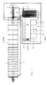
- the fermenter or fermentation reactor 1 This becomes one-sided via a preferably heated feed line 2 in graft flow mode continuously or quasi continuously with fed fresh biogenic waste. This is done using a feeding unit 3.
- the feeding unit 3 is additional via a suction line 4 with the fermenter or cooking reactor connected.
- the feed unit 3 is designed so that it both in one direction and in the other can promote. This can be done, for example, using a bidirectional Pump system take place. Via line 4 can thus fermented good near the outlet area to the fermenter 1 are removed and into the feed line 2 for vaccinating the Fresh goods are fed.
- The is accordingly Feed unit 3 provided with drive means 5.
- the Shredder 7 is not visible in this figure. That in Graft current operation through the fermenter 1 conveyed material reaches the outside via a discharge screw 8. The discharged, fermented material still gets on rotting, before it is used as high quality compost.
- water can be piped and a water admixing valve 9 to the fresh material as required, preferably added in the area of the feed unit 3 become.
- This Shredder can be designed to be mobile, so that shredded fresh material directly into the inventive Interim storage 20 can be delivered.
- the shredder can the shredded fresh material also in another place eject it so that in a further step, for example intermediate storage 20 by means of a crane or gripper can be supplied.
- This intermediate storage 20 consists of a cargo space 21 which consists of an open top elongated trough 22, for example a metal trough, consists.
- the floor of the loading space 21 is a conveyor floor 23 realized.
- the conveyor floor 23 can be like this in the art For example, for loading wagons in the agricultural sector is known as Scraper floor to be constructed.
- the Delivery direction of the conveyor floor 23 is in the drawing indicated by an arrow F.
- a dosing and Discharge unit 24 shown at the end of the hold 21 or the trough 22 .
- the dosing and Discharge unit 24 can also be designed the same as with a loading wagon.
- the dosing and discharge unit 24 but does not necessarily need an actively promoting element his.
- the dosing and discharge unit 24 can be done in the simplest Case be a retaining element.
- Such a retention element corresponds approximately to a storage or lock plate.
- This Storage or lock plate can be adjusted in height and / or adjust the distance relative to the conveyor floor. With that leaves the discharge quantity of the fresh material, which on the Conveyor floor lies and towards the dosing and Discharge unit 24 is transported, metered.
- Such a dosing and Discharge unit 24 can also as revolving chain scratch be designed. This Chain scratch then conveys the material at the end of the Conveyor floor 23 by a not recognizable here Discharge gap down on a conveyor line that finally leads to the feed unit 3.
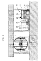
- FIG. 2 shows a schematically represented section through the plant of Figure 1 along the line A-A drawn.
- the fermenter respectively Fermentation reactor 1 shown in section, and you can see it cylindrical cross section.
- the cross-sectional shape of the fermentation reactor does not matter. So of course fermenters with U-shaped can or rectangular cross-sectional shapes can be used. It is also irrelevant whether the fermenter is a concrete fermenter or as shown here is made of steel. That is to the right of the fermenter in a separate room Interim storage facility 20 can be seen on the right. You can see the two Side walls of the trough 22 and the dosing and Discharge unit 24 and the conveyor floor 23.
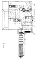
- FIG 3 a slightly different system is shown.
- a fermenter or fermentation reactor 1 is also present here, which is fed by a preferably heated feed line.
- the bidirectionally operating feed unit 3 is in turn connected to the fermenter 1 via a suction line 4.
- the acceptance unit 30 is also shown, which is shown as an acceptance space 30 in the embodiment shown.
- a truck 31 can deposit the approached fresh goods in the acceptance room 30.
- a mobile shredder 7 is shown here as an inventive feature.
- the mobile shredder 7 can be loaded via a crane 32 and the shredded material can also be fed to the loading space by means of the crane.
- the shredder comprises a relatively large hopper 33 which, as already mentioned, can be loaded by means of a crane 32.
- the mobile shredder is arranged and movable in such a way that it can shred fresh material from the receiving space 30 and then discharge it in the shredded state into the loading space 21 or at another location in the swivel range of the crane 32.
- the shredder 7 has corresponding knife rollers and / or grinding rollers in order to shred the fresh material into the desired unit size.
- a sieve can be provided over the funnel 33 in order to separate certain elements that are too large.
- the shredded material is discharged by means of the discharge unit 34, here unwanted metal parts can be removed by means of a magnetic separator.
- the drive unit of the shredder is shown at 37.
- shredder is understandably dependent on the nature of the biowaste delivered to the fermentation plant. If the material has been shredded beforehand, for example before transport, or if the material does not require shredding, then no shredder is required in the fermentation plant.
- the mobile shredders shown in the exemplary embodiments have the advantage that they can be removed from the system very easily in such cases and can be used for other purposes, for example.
- the acceptance unit can be formed from a stand for such a container. If the material delivered in the container is already in a particle size that allows feeding into the fermenter, such a container can advantageously be connected directly to the loading space 21, or the green material can be delivered directly from the container to the loading space 21.
- the other infrastructural elements here on the Drawing are still recognizable are for the invention per se not of importance, but of course for one Fermentation plant needed. Therefore, purely as a supplement still pointed out these elements.
- the fermenter 1 is emptied here via a discharge screw 8.
- the fermented Well is deposited in open post-rotting bunkers 35. On so-called tire charger promotes this from the fermenter 8 discharged material in the corresponding open Nachrottebunker 35.
- the Nachrottebunker 35 are after one corresponding scheme filled and emptied.
- the one in the Nachrottebunker 35 lying compost can depending on Intended use after a shorter or longer storage period continue to be used.
- the fresh material needs thus no longer with fixed from the acceptance point Plant components are promoted to a shredder and in particular, the shredded material no longer needs a silo-like intermediate storage from which it has to be retrieved afterwards, but is, as already mentioned, practically on a conveyor line delivered with large storage capacity.
- the interim storage facility 20, here as a cargo space 21 with conveyor floor 23 and Discharge unit 24 is designed, practically allows one fluid interim storage by means of which one Fermentation plant can be built much cheaper.
Landscapes
- Engineering & Computer Science (AREA)
- Life Sciences & Earth Sciences (AREA)
- Chemical & Material Sciences (AREA)
- Health & Medical Sciences (AREA)
- Biochemistry (AREA)
- Organic Chemistry (AREA)
- Molecular Biology (AREA)
- General Chemical & Material Sciences (AREA)
- Bioinformatics & Cheminformatics (AREA)
- Zoology (AREA)
- Chemical Kinetics & Catalysis (AREA)
- Environmental & Geological Engineering (AREA)
- Biotechnology (AREA)
- Microbiology (AREA)
- Wood Science & Technology (AREA)
- Genetics & Genomics (AREA)
- Biomedical Technology (AREA)
- General Engineering & Computer Science (AREA)
- General Health & Medical Sciences (AREA)
- Sustainable Development (AREA)
- Oil, Petroleum & Natural Gas (AREA)
- Mechanical Engineering (AREA)
- Fertilizers (AREA)
- Processing Of Solid Wastes (AREA)
- Apparatus Associated With Microorganisms And Enzymes (AREA)
Abstract
Description
- Figur 1
- zeigt eine Gesamtansicht der erfindungsgemässen Anlage in vereinfachter Darstellung und unter Weglassung der infrastrukturellen Einheiten und der Anlagenteile, die mit der Gasgewinnung, Lagerung und Energieumwandlung für interne und externe Zwecke zusammenhängen.
- Figur 2
- stellt einen Vertikalschnitt durch die Anlage gemäss der Figur 1 entlang der Linie A-A dar.
- Figur 3
- zeigt insbesondere die infrastrukturellen Massnahmen im Bereich der Annahme der biogenen Abfälle und der Weiterbehandlung des vergorenen Gutes.
Der Einsatz eines Zerkleinerers ist verständlicherweise abhängig von der Beschaffenheit des zur Gäranlage angelieferten Bioabfalles. Falls das Material schon vorgängig zerkleinert wurde, zum Beispiel vor dem Transport, oder falls das Material keiner Zerkleinerung bedarf, so ist auch kein Zerkleinerer in der Vergärungsanlage nötig. Die in den Ausführungsbeispielen gezeigten mobilen Zerkleinerer haben den Vorteil, dass sie in solchen Fällen sehr einfach aus der Anlage entfernt und zum Beispiel anderweitig eingesetzt werden können. Wird das Frischgut in Containern angeliefert, so kann die Annahmeeinheit von einem Standplatz für einen solchen Container gebildet werden. Liegt das im Container angelieferte Material bereits in einer Partikelgrösse vor, die ein Einspeisen in den Fermenter erlaubt, so kann ein solcher Container vorteilhafterweise direkt an den Laderaum 21 angeschlossen werden, respektive das Grüngut aus dem Container direkt an den Laderaum 21 abgegeben werden.
Claims (10)
- Kontinuierlich oder quasi kontinuierlich arbeitende Anlage zum Fermentieren beziehungsweise Vergären von biogenen Abfällen, die mindestens je eine Annahmeeinheit (30), ein Zwischenlager (20), eine Speiseeinheit (3) und einen Fermenter (1) umfasst, dadurch gekennzeichnet, dass das Zwischenlager (20) für die zerkleinerten biogenen Abfälle aus einem Laderaum (21) mit Förderboden (23) und einer Dosier- und Austragseinheit (24) besteht.
- Anlage nach Patentanspruch 1, dadurch gekennzeichnet, dass die Dosier- und Austragseinheit (24) mit einer Förderstrecke (27, 28) in Verbindung steht, welche das ausgetragene Material zu der Speiseeinheit (3) fördert.
- Anlage nach Patentanspruch 1, dadurch gekennzeichnet, dass der Laderaum (21) eine Muldenkonstruktion ist.
- Anlage nach Patentanspruch 1, dadurch gekennzeichnet, dass der Förderboden (23) als Kratzboden oder als Endlos-Förderband oder als Moving- oder Running Floor konstruiert ist.
- Anlage nach Patentanspruch 1, dadurch gekennzeichnet, dass die Dosier- und Austragseinheit (24) in Förderrichtung des Förderbodens (23) am Ende angeordnet ist.
- Anlage nach den Patentansprüchen 2 und 5, dadurch gekennzeichnet, dass die Dosier- und Austragseinheit (24) ein umlaufender Kettenkratzer ist, mit dem das Material am Ende des Förderbodens (23) durch einen Austragsspalt (29) nach unten auf die Förderstrecke (27, 28) gelangt.
- Anlage nach Patentanspruch 1, dadurch gekennzeichnet, dass die Dosier- und Austragseinheit (24) ein gegenüber dem Förderboden (23) in der Höhe verstellbar distanziertes Rückhalteelement ist.
- Anlage nach Patentanspruch 1, dadurch gekennzeichnet, dass die Anlage einen Zerkleinerer (7) umfasst.
- Anlage nach Patentanspruch 8, dadurch gekennzeichnet, dass der Zerkleinerer (7) ein mobiler Zerkleinerer (7) ist, der über den Laderaum bewegbar ist.
- Anlage nach einem der Patentansprüche 1 oder 8, dadurch gekennzeichnet, dass ein Gerät (32) zum Beschicken des Zerkleinerers (7) und/oder des Laderaumes (21) mit biogenen Abfällen vorhanden ist.
Applications Claiming Priority (2)
| Application Number | Priority Date | Filing Date | Title |
|---|---|---|---|
| CH140899 | 1999-07-28 | ||
| CH140899A CH697135A5 (de) | 1999-07-28 | 1999-07-28 | Vergärungsanlage mit Vorrichtung zur Materialbeschickung |
Publications (2)
| Publication Number | Publication Date |
|---|---|
| EP1074313A2 true EP1074313A2 (de) | 2001-02-07 |
| EP1074313A3 EP1074313A3 (de) | 2003-06-25 |
Family
ID=4209756
Family Applications (1)
| Application Number | Title | Priority Date | Filing Date |
|---|---|---|---|
| EP00810653A Withdrawn EP1074313A3 (de) | 1999-07-28 | 2000-07-21 | Vergärungsanlage mit Vorrichtung zur Materialbeschickung |
Country Status (2)
| Country | Link |
|---|---|
| EP (1) | EP1074313A3 (de) |
| CH (1) | CH697135A5 (de) |
Cited By (2)
| Publication number | Priority date | Publication date | Assignee | Title |
|---|---|---|---|---|
| CN111774398A (zh) * | 2020-06-11 | 2020-10-16 | 广西力源宝科技有限公司 | 厨余垃圾生态处理终端及处理方法 |
| CN116424889A (zh) * | 2022-08-26 | 2023-07-14 | 北京中航泰达环保科技股份有限公司 | 一种自动循环排料方法 |
Family Cites Families (2)
| Publication number | Priority date | Publication date | Assignee | Title |
|---|---|---|---|---|
| GB490426A (en) * | 1937-02-12 | 1938-08-12 | Eau Et Assainissement Anciens | Method for the treatment by fermentation of waste refuse and of vegetation and apparatus for the application of said process |
| DE4103715A1 (de) * | 1990-02-12 | 1991-07-11 | Annerose Kutzer | Anlage und verfahren zur behandlung von hausmuell und hausmuellaehnlichen gewerbeabfaellen |
-
1999
- 1999-07-28 CH CH140899A patent/CH697135A5/de not_active IP Right Cessation
-
2000
- 2000-07-21 EP EP00810653A patent/EP1074313A3/de not_active Withdrawn
Cited By (3)
| Publication number | Priority date | Publication date | Assignee | Title |
|---|---|---|---|---|
| CN111774398A (zh) * | 2020-06-11 | 2020-10-16 | 广西力源宝科技有限公司 | 厨余垃圾生态处理终端及处理方法 |
| CN111774398B (zh) * | 2020-06-11 | 2023-11-24 | 广西力源宝科技有限公司 | 厨余垃圾生态处理终端及处理方法 |
| CN116424889A (zh) * | 2022-08-26 | 2023-07-14 | 北京中航泰达环保科技股份有限公司 | 一种自动循环排料方法 |
Also Published As
| Publication number | Publication date |
|---|---|
| CH697135A5 (de) | 2008-05-15 |
| EP1074313A3 (de) | 2003-06-25 |
Similar Documents
| Publication | Publication Date | Title |
|---|---|---|
| EP1251165B1 (de) | Biomasse-Zudosier-Vorrichtung an einem Fermenter einer Biogasanlage | |
| EP0476217A1 (de) | Anlage zur Verwertung organischer Stoffe | |
| AT11640U1 (de) | Vorrichtung zur gärgutbeschickung einer gäranlage | |
| DE2937390A1 (de) | Verfahren zur aeroben verrottung von organischen abfallstoffen in einem verrottungsbunker sowie eine ausbildung zur durchfuehrung des verfahrens | |
| DE19909328B4 (de) | Abfallverwertungsverfahren | |
| WO2011076444A1 (de) | Vorrichtung und verfahren zum fermentieren, nachrotten und intensivrotten von verarbeitungsprodukten | |
| DE202008010638U1 (de) | Rührwerk mit Einbringsystem für Feststoffe | |
| EP1074313A2 (de) | Vergärungsanlage mit Vorrichtung zur Materialbeschickung | |
| EP1076051A2 (de) | Vergärungsanlage mit Vorrichtung zur Materialaufbereitung | |
| DE102005001783B4 (de) | Biogasanlagen-Feststoffbeschickungsvorrichtung an einem Fermenter einer Biogasanlage | |
| EP1072574B1 (de) | Vergärungsanlage mit Vorrichtung zur Entwässerung von Fermentationsprodukten | |
| EP1170357A1 (de) | Feststoff-Zudosier-Vorrichtung an einem Fermenter einer Biogasanlage | |
| DE102005021454A1 (de) | Beschickungsvorrichtung, insbesondere für Biogas- oder Recyclinganlagen | |
| DE20216090U1 (de) | Vorrichtung zum Einbringen von insbesondere aus Stallabfällen stammenden, landwirtschaftlichen Feststoffen in Gülle-Fermenter | |
| EP1013614B1 (de) | Entwässerung von Fermentationsprodukten mit Schneckenpresse | |
| DE20308930U1 (de) | Biogasanlage | |
| EP2803729B1 (de) | Verfahren zur Herstellung von Biogas durch kontinuierliche Vergärung von Substratmischungen und Biogasanlage zur kontinuierlichen Vergärung von Substratmischungen | |
| EP2465918B1 (de) | Biomassetrockenfermenter mit kontinuierlicher Beschickung und Entnahme | |
| DE202010004564U1 (de) | Doppelschneckenextruder zum thermomechanischen Aufschluß von organischen Roh- und Reststoffen | |
| ITTO20090445A1 (it) | Dispositivo e procedimento per il trattamento di liquami organici, particolarmente liquami di origine zootecnica | |
| LU503049B1 (de) | Rückstandsvorbehandlungsvorrichtung zur Abwasserbehandlung | |
| DE202009004830U1 (de) | Anlage zur Beschickung eines Fermenters | |
| WO2015176697A1 (de) | Verfahren und vorrichtung zur behandlung und verwendung von bioabfall, restmüll und deponiematerial von hausmülldeponien für biogasanlagen | |
| EP0799812A1 (de) | Beschickungseinrichtung für eine Vergärungsanlage | |
| EP2216273B1 (de) | Pneumatisches Müllsaugsystem mit einer Speichervorrichtung sowie ein Verfahren zum Überführen von Müllobjekten mittels eines solchen Müllsaugsystems |
Legal Events
| Date | Code | Title | Description |
|---|---|---|---|
| PUAI | Public reference made under article 153(3) epc to a published international application that has entered the european phase |
Free format text: ORIGINAL CODE: 0009012 |
|
| AK | Designated contracting states |
Kind code of ref document: A2 Designated state(s): AT BE CH CY DE DK ES FI FR GB GR IE IT LI LU MC NL PT SE |
|
| AX | Request for extension of the european patent |
Free format text: AL;LT;LV;MK;RO;SI |
|
| PUAL | Search report despatched |
Free format text: ORIGINAL CODE: 0009013 |
|
| AK | Designated contracting states |
Designated state(s): AT BE CH CY DE DK ES FI FR GB GR IE IT LI LU MC NL PT SE |
|
| AX | Request for extension of the european patent |
Extension state: AL LT LV MK RO SI |
|
| 17P | Request for examination filed |
Effective date: 20030915 |
|
| AKX | Designation fees paid |
Designated state(s): AT BE CH CY DE DK ES FI FR GB GR IE IT LI LU MC NL PT SE |
|
| GRAP | Despatch of communication of intention to grant a patent |
Free format text: ORIGINAL CODE: EPIDOSNIGR1 |
|
| GRAS | Grant fee paid |
Free format text: ORIGINAL CODE: EPIDOSNIGR3 |
|
| STAA | Information on the status of an ep patent application or granted ep patent |
Free format text: STATUS: THE APPLICATION IS DEEMED TO BE WITHDRAWN |
|
| 18D | Application deemed to be withdrawn |
Effective date: 20050201 |