EP1074307B1 - Vorrichtung und Verfahren zum Aufbringen eines Kunststoffstrangs auf eine Unterlage - Google Patents
Vorrichtung und Verfahren zum Aufbringen eines Kunststoffstrangs auf eine Unterlage Download PDFInfo
- Publication number
- EP1074307B1 EP1074307B1 EP00115013A EP00115013A EP1074307B1 EP 1074307 B1 EP1074307 B1 EP 1074307B1 EP 00115013 A EP00115013 A EP 00115013A EP 00115013 A EP00115013 A EP 00115013A EP 1074307 B1 EP1074307 B1 EP 1074307B1
- Authority
- EP
- European Patent Office
- Prior art keywords
- substrate
- light
- plastic
- nozzle
- liquid
- Prior art date
- Legal status (The legal status is an assumption and is not a legal conclusion. Google has not performed a legal analysis and makes no representation as to the accuracy of the status listed.)
- Expired - Lifetime
Links
- 229920003023 plastic Polymers 0.000 title claims abstract description 50
- 239000004033 plastic Substances 0.000 title claims abstract description 50
- 238000000034 method Methods 0.000 title claims abstract description 21
- 239000000758 substrate Substances 0.000 title claims description 26
- 239000007788 liquid Substances 0.000 claims abstract description 26
- 238000010438 heat treatment Methods 0.000 claims description 31
- 235000011837 pasties Nutrition 0.000 claims description 25
- 230000003287 optical effect Effects 0.000 claims description 13
- 239000000853 adhesive Substances 0.000 claims description 6
- 230000001070 adhesive effect Effects 0.000 claims description 6
- 230000004913 activation Effects 0.000 claims description 4
- 239000000565 sealant Substances 0.000 claims description 4
- 239000002184 metal Substances 0.000 claims description 3
- 230000006698 induction Effects 0.000 claims description 2
- 229920001187 thermosetting polymer Polymers 0.000 claims 1
- 238000011144 upstream manufacturing Methods 0.000 claims 1
- 239000000463 material Substances 0.000 abstract description 4
- 230000005855 radiation Effects 0.000 abstract 1
- 238000007789 sealing Methods 0.000 description 6
- 239000011347 resin Substances 0.000 description 5
- 229920005989 resin Polymers 0.000 description 5
- 239000011324 bead Substances 0.000 description 4
- 238000001994 activation Methods 0.000 description 3
- 238000005260 corrosion Methods 0.000 description 2
- 230000007797 corrosion Effects 0.000 description 2
- 239000010453 quartz Substances 0.000 description 2
- VYPSYNLAJGMNEJ-UHFFFAOYSA-N silicon dioxide Inorganic materials O=[Si]=O VYPSYNLAJGMNEJ-UHFFFAOYSA-N 0.000 description 2
- 230000001133 acceleration Effects 0.000 description 1
- 230000003213 activating effect Effects 0.000 description 1
- 230000006835 compression Effects 0.000 description 1
- 238000007906 compression Methods 0.000 description 1
- 230000001419 dependent effect Effects 0.000 description 1
- 239000013305 flexible fiber Substances 0.000 description 1
- 238000009957 hemming Methods 0.000 description 1
- 238000012986 modification Methods 0.000 description 1
- 230000004048 modification Effects 0.000 description 1
- 238000007493 shaping process Methods 0.000 description 1
- 238000007725 thermal activation Methods 0.000 description 1
- 238000009281 ultraviolet germicidal irradiation Methods 0.000 description 1
- XLYOFNOQVPJJNP-UHFFFAOYSA-N water Substances O XLYOFNOQVPJJNP-UHFFFAOYSA-N 0.000 description 1
Images

Classifications
-
- B—PERFORMING OPERATIONS; TRANSPORTING
- B05—SPRAYING OR ATOMISING IN GENERAL; APPLYING FLUENT MATERIALS TO SURFACES, IN GENERAL
- B05C—APPARATUS FOR APPLYING FLUENT MATERIALS TO SURFACES, IN GENERAL
- B05C5/00—Apparatus in which liquid or other fluent material is projected, poured or allowed to flow on to the surface of the work
- B05C5/02—Apparatus in which liquid or other fluent material is projected, poured or allowed to flow on to the surface of the work the liquid or other fluent material being discharged through an outlet orifice by pressure, e.g. from an outlet device in contact or almost in contact, with the work
- B05C5/0208—Apparatus in which liquid or other fluent material is projected, poured or allowed to flow on to the surface of the work the liquid or other fluent material being discharged through an outlet orifice by pressure, e.g. from an outlet device in contact or almost in contact, with the work for applying liquid or other fluent material to separate articles
- B05C5/0212—Apparatus in which liquid or other fluent material is projected, poured or allowed to flow on to the surface of the work the liquid or other fluent material being discharged through an outlet orifice by pressure, e.g. from an outlet device in contact or almost in contact, with the work for applying liquid or other fluent material to separate articles only at particular parts of the articles
- B05C5/0216—Apparatus in which liquid or other fluent material is projected, poured or allowed to flow on to the surface of the work the liquid or other fluent material being discharged through an outlet orifice by pressure, e.g. from an outlet device in contact or almost in contact, with the work for applying liquid or other fluent material to separate articles only at particular parts of the articles by relative movement of article and outlet according to a predetermined path
-
- B—PERFORMING OPERATIONS; TRANSPORTING
- B05—SPRAYING OR ATOMISING IN GENERAL; APPLYING FLUENT MATERIALS TO SURFACES, IN GENERAL
- B05C—APPARATUS FOR APPLYING FLUENT MATERIALS TO SURFACES, IN GENERAL
- B05C9/00—Apparatus or plant for applying liquid or other fluent material to surfaces by means not covered by any preceding group, or in which the means of applying the liquid or other fluent material is not important
- B05C9/08—Apparatus or plant for applying liquid or other fluent material to surfaces by means not covered by any preceding group, or in which the means of applying the liquid or other fluent material is not important for applying liquid or other fluent material and performing an auxiliary operation
- B05C9/14—Apparatus or plant for applying liquid or other fluent material to surfaces by means not covered by any preceding group, or in which the means of applying the liquid or other fluent material is not important for applying liquid or other fluent material and performing an auxiliary operation the auxiliary operation involving heating or cooling
-
- B—PERFORMING OPERATIONS; TRANSPORTING
- B29—WORKING OF PLASTICS; WORKING OF SUBSTANCES IN A PLASTIC STATE IN GENERAL
- B29C—SHAPING OR JOINING OF PLASTICS; SHAPING OF MATERIAL IN A PLASTIC STATE, NOT OTHERWISE PROVIDED FOR; AFTER-TREATMENT OF THE SHAPED PRODUCTS, e.g. REPAIRING
- B29C67/00—Shaping techniques not covered by groups B29C39/00 - B29C65/00, B29C70/00 or B29C73/00
- B29C67/24—Shaping techniques not covered by groups B29C39/00 - B29C65/00, B29C70/00 or B29C73/00 characterised by the choice of material
- B29C67/246—Moulding high reactive monomers or prepolymers, e.g. by reaction injection moulding [RIM], liquid injection moulding [LIM]
Definitions
- the invention relates to a device for applying a plastic strand to a substrate with a pressurizable with a curable liquid or pasty plastic nozzle head having a preferably closable with a valve needle applicator, wherein the nozzle head and the base are so relatively movable by means of a robot assembly in that the application nozzle is guided along a predetermined path located on the support. Further, the invention relates to a method for applying a plastic strand to a substrate.
- Devices of this type are used, for example, in the automotive industry for the sealing of flanged seams.
- the curing of the plastic strand takes place there mainly by thermal heating of the plastic material.
- the plastic strand is intended to protect the hemming seam against water ingress and corrosion.
- the known method is considered to be disadvantageous that the often unavoidable air pockets lead in the area of the flanged seam during the thermal activation by the expanding air to blistering. The bubbles disturb the appearance and increase the risk of corrosion.
- the EP 0 581 417 A1 shows an apparatus and method for applying a plastic to a substrate. Specifically, it is about the application of lettering on clothing. Of the EP 0 581 417 A1 is not apparent to activate the applied plastic photochemically by means of UV light.
- the US 4,970,399 shows an apparatus for processing UV-curable reaction resins, said resin is passed through an irradiation chamber (4) and undergoes irradiation before leaving the irradiation room. The reaction resin irradiated in the irradiation room is then led into a mold.
- the present invention seeks to improve the device and the method of the type specified in that blistering during application and curing of the plastic strand is avoided.
- the solution according to the invention is based on the idea that the liquid or pasty plastic is irradiated shortly before and / or after the order in the passage with UV light and thereby activated photochemically for curing.
- a UV light source for the photochemical activation of the plastic which has at least one light exit point pointing in the direction of the support in the direction of movement behind the nozzle head.
- a UV light source for the photochemical activation of the plastic can be provided which has at least one light exit point opening into the flow path of the liquid or pasty plastic in front of the application nozzle.
- a preferred embodiment of the invention provides that the nozzle head is arranged on the end member of the robot assembly and with this relative to the held pad along the predetermined path is movable.
- the UV light source can be arranged on the robot arrangement or on the nozzle head and optically connected to the light exit point.
- the light source is expediently connected to the at least one light exit point via at least one quartz rod or at least one optical waveguide.
- An advantageous embodiment of the invention provides that the UV light source is arranged in a lamp housing open in the direction of the base.
- a mirror arrangement directing the UV light to the point of application along the movement path can be arranged in the lamp housing.
- the lamp housing may be delimited by a flexible curtain which can be applied with its edge against the base.
- the curtain advantageously has an open-edged recess on its front and rear edge part in the direction of movement, so that the plastic strand is not touched by the curtain when the robot moves past.
- a further advantageous embodiment of the invention provides that the UV light source has at least one preferably arranged on the robot assembly UV lamp and guided by the UV lamp to the election exit flexible fiber optic arrangement.
- the optical waveguide arrangement expediently comprises a plurality of optical waveguides, their light exit openings facing the underlay in the direction of movement behind the nozzle head one behind the other are arranged. At least one of the optical waveguides can be guided by a UV lamp to a light exit point within the nozzle head.
- a heating device for heating the plastic which is also thermally activatable, can additionally be provided.
- the heating device has a heating element arranged in the nozzle head.
- the heating device may have a preferably arranged on the robot assembly hot air blower, which may have at least one preferably arranged on the end member of the robot assembly, pointing in the direction of support hot air nozzle.
- the at least one hot air nozzle can be arranged in the direction of movement behind the application nozzle and directed to the already applied adhesive strand.
- the heating device may have a heating unit which heats the base at least along the movement path and which may be designed, for example, as an induction heater, infrared heater or NIR heater (near IR).
- a heating unit which heats the base at least along the movement path and which may be designed, for example, as an induction heater, infrared heater or NIR heater (near IR).
- the method is achieved with the inventive measures that the liquid or pasty plastic is briefly irradiated before the order and / or after the order on the substrate with UV light and is thereby brought photochemically to cure.
- the liquid or pasty plastic is irradiated in the passage along a flow path with the UV light via a light window, which is at the same time wetted and cleaned by the passing liquid or pasty plastic.
- the irradiation can take place via a quartz rod or optical waveguide which is exposed to UV light on the inlet side.
- liquid or pasty plastic is irradiated after application to the substrate with UV light, this can be done by passing along the trajectory UV light source in passing.
- An acceleration of curing can be achieved by heating the thermally activatable liquid or pasty plastic either before or after the UV irradiation.
- the robot assembly 10 shown in the drawing is intended primarily for sealing glued bead seams 12 of motor vehicle parts 14.
- the robot 10 carries for this purpose at its end member 16, a nozzle head 18 which is acted upon via a flexible hose with a sealant of liquid or pasty reaction resin and having a closable with a valve needle 22 application nozzle 24.
- the operation of the valve needle 22 via a cylinder-piston assembly 48, the piston 50 is moved in the open position via the robot control against the force of a closing spring 51 pneumatically upwards and 51 in the closed position under the action of the closing spring down.
- the nozzle head is movable relative to the support 14 relative to the support 14 along a predetermined path (flanging edge 12) in the direction of the arrow 30 relative to the support (vehicle part 14) and brings a plastic strand 32 onto the support 14 via the application nozzle.
- the nozzle edge 28 at its in and counter to the direction of movement 30 facing edge portions 34 each one with the nozzle opening 26th communicating, the pad 14 down towards open shaping recess 36, while it is pressed against its opposite surface, facing transversely to the direction of movement 30 edge portions 38 against the pad 14.
- the nozzle head 18 is pivotably connected to the end member 16 of the robot assembly 10 about an axis 40 oriented transversely to the direction of movement at a distance from the application nozzle 24.
- the nozzle head 18 has for this purpose a boom 42, with which it is articulated on an obliquely downward over the end member 16 projecting cantilever 44.
- the spring is designed as a clamped between the boom 42 and the cantilever 44 compression spring 46.
- a UV light source 52 is arranged, which is located in the direction of movement 30 behind the nozzle head 18, and has the task of photochemically activating the curing process of the applied on the substrate 14 sealant strand 32.
- UV light source 52 is disposed in an open towards the base 14 lamp housing 54 which is bounded by an engageable with its edge 56 against the pad flexible curtain 58.
- the curtain has, in the region of its front edge and rear edge region, not shown, with respect to the direction of movement 30, open-edged recesses for the non-contact passage of the sealant strand 32.
- a mirror arrangement 60 which directs the UV light to an application site along the movement path is provided.
- the lamp housing 54 is inclined relative to a vertical plane 62 to an adjustable preferably via the robot control angle ⁇ or pivotally mounted on the robot end member.
- it is in the direction of the double arrows 64 can be raised and lowered vertically attached to the end member 16.
- an optical waveguide 65 is additionally branched off, which opens with its light exit point in the flow path of the liquid or pasty plastic within the nozzle head 18.
- the UV light source 52 consists of a lamp housing 54 arranged at a greater distance from the end member 16 on the robot assembly 10 with at least one UV lamp and a plurality of light waveguides 66 led from the lamp housing 54 to a holder 68 fixed to the final member.
- the light exit points of the optical waveguides 66 follow down in the direction of beading 12. They are fixed in the direction of movement behind the nozzle head 18 in succession to the holder 68.
- a heating device for heating the same thermally activatable plastic is provided.
- the heating device has a heating element 70 arranged in the nozzle head, which can be heated electrically and via which the plastic material flowing past is brought to an elevated temperature and thermally activated.
- a heating unit which has two pointing in the direction of support, for example, designed as an infrared heater or hot air nozzles heating elements 74,76.
- the heating element 74 is arranged in the direction of movement in front of the application nozzle 24. It heats the pad 14 in the region of the flange 12, so that the adhesive strand is heated when it hits the pad and thermally activated.
- the heating element 76 is arranged in the direction of movement behind the application nozzle and directed to the already applied adhesive strand.
- the invention relates to an apparatus and a method for applying an adhesive strand to a substrate.
- the apparatus and method are intended for example in the automotive industry for sealing bead seams 12 to sheet metal parts 14.
- the device comprises a preferably attachable to the end member 16 of a robot assembly 10, relative to the substrate 14 along a predetermined path 12 movable nozzle head 18 which is acted upon by a curable liquid or pasty plastic under pressure and having a preferably with a valve needle 22 closable applicator 24 ,
- a UV light source for photochemical activation of the plastic is proposed according to the invention, the at least one arranged on the end member 16, in Moving direction behind the nozzle head 18 in the direction of base 14 facing light exit point or alternatively has at least one opening in front of the application nozzle 24 in the flow path of the liquid or pasty plastic light exit point.
Landscapes
- Engineering & Computer Science (AREA)
- Mechanical Engineering (AREA)
- Application Of Or Painting With Fluid Materials (AREA)
- Coating Apparatus (AREA)
- Adhesives Or Adhesive Processes (AREA)
- Processing And Handling Of Plastics And Other Materials For Molding In General (AREA)
Description
- Die Erfindung betrifft eine Vorrichtung zum Aufbringen eines Kunststoffstrangs auf eine Unterlage mit einem mit einem aushärtbaren flüssigem oder pastösem Kunststoff unter Druck beaufschlagbaren Düsenkopf, der eine vorzugsweise mit einer Ventilnadel verschließbare Auftragsdüse aufweist, wobei der Düsenkopf und die Unterlage mittels einer Roboteranordnung so relativ zueinander bewegbar sind, daß die Auftragsdüse entlang einer auf der Unterlage befindlichen vorgegebenen Bahn geführt wird. Weiter bezieht sich die Erfindung auf ein Verfahren zum Aufbringen eines Kunststoffstrangs auf eine Unterlage.
- Vorrichtungen dieser Art werden beispielsweise in der Automobilindustrie zur Versiegelung von Bördelnähten verwendet. Die Aushärtung des Kunststoffstrangs erfolgt dort überwiegend durch thermische Aufheizung des Kunststoffmaterials. Der Kunststoffstrang soll die Bördelnaht gegen Wasserzutritt und Korrosion schützen. Bei dem bekannten Verfahren wird als nachteilig angesehen, daß die oft unvermeidlichen Lufteinschlüsse im Bereich der Bördelnaht bei der thermischen Aktivierung durch die sich ausdehnende Luft zur Blasenbildung führen. Die Blasen stören das Aussehen und erhöhen die Korrosionsgefahr.
- Die
EP 0 581 417 A1 zeigt eine Vorrichtung und ein Verfahren zum Aufbringen eines Kunststoffes auf eine Unterlage. Konkret geht es um das Aufbringen von Schriftzügen auf Bekleidungsstücke. DerEP 0 581 417 A1 ist nicht zu entnehmen, den aufgebrachten Kunststoff mittels UV-Licht photochemisch zu aktivieren. - Die
US 4,970,399 zeigt eine Vorrichtung zum Verarbeiten von UV-härtbaren Reaktionsharzen, wobei dieses Harz durch einen Bestrahlungsraum (4) geführt wird und vor dem Verlassen des Bestrahlungsraumes eine Bestrahlung erfährt. Das in dem Bestrahlungsraum bestrahlte Reaktionsharz wird dann in eine Gießform geleitet. - Hierbei handelt es sich also um eine stationäre Einrichtung, wobei das mit UV-Licht bestrahlte Harz zum Versiegeln von elektronischen Bauelementen einsetzbar ist.
- Ausgehend hiervon liegt der Erfindung die Aufgabe zugrunde, die Vorrichtung und das Verfahren der eingangs angegebenen Art dahingehend zu verbessern, daß eine Blasenbildung beim Aufbringen und Aushärten des Kunststoffstrangs vermieden wird.
- Zur Lösung dieser Aufgabe werden die in den Ansprüchen 1, 21, und 30 angegebenen Merkmalskombinationen vorgeschlagen. Vorteilhafte Ausgestaltungen und Weiterbildungen der Erfindung ergeben sich aus den abhängigen Ansprüchen.
- Die erfindungsgemäße Lösung geht von dem Gedanken aus, daß der flüssige oder pastöse Kunststoff kurz vor und/oder nach dem Auftrag im Durchlauf mit UV-Licht bestrahlt und dabei fotochemisch zum Aushärten aktiviert wird.
- Um dies zu erreichen, wird gemäß einer ersten Erfindungsalternative eine UV-Lichtquelle zur fotochemischen Aktivierung des Kunststoffs vorgeschlagen, die mindestens eine in Bewegungsrichtung hinter dem Düsenkopf in Richtung Unterlage weisende Lichtaustrittsstelle aufweist. Gemäß einer vorteilhaften oder alternativen Ausgestaltung der Erfindung kann eine UV-Lichtquelle zur fotochemischen Aktivierung des Kunststoffs vorgesehen werden, die mindestens eine in den Strömungsweg des flüssigen oder pastösen Kunststoffs vor der Auftragsdüse mündende Lichtaustrittsstelle aufweist.
- Eine bevorzugte Ausgestaltung der Erfindung sieht vor, daß der Düsenkopf am Endglied der Roboteranordnung angeordnet und mit dieser relativ zur festgehaltenen Unterlage entlang der vorgegebenen Bahn bewegbar ist. Die UV-Lichtquelle kann dabei an der Roboteranordnung oder am Düsenkopf angeordnet und optisch mit der Lichtaustrittsstelle verbunden sein. Die Lichtquelle ist zweckmäßig über mindestens einen Quarzstab oder mindestens einen Lichtwellenleiter mit der mindestens einen Lichtaustrittsstelle verbunden.
- Eine vorteilhafte Ausgestaltung der Erfindung sieht vor, daß die UV-Lichtquelle in einem in Richtung Unterlage offenen Lampengehäuse angeordnet ist. In dem Lampengehäuse kann eine das UV-Licht zur Applikationsstelle entlang der Bewegungsbahn lenkende Spiegelanordnung angeordnet sein. Weiter kann das Lampengehäuse einen mit seinem Rand gegen die Unterlage anlegbaren flexiblen Vorhang begrenzt sein. Der Vorhang weist vorteilhafterweise an seiner in Bewegungsrichtung vorderen und rückwärtigen Randpartie eine randoffene Ausnehmung auf, so daß der Kunststoffstrang beim Vorbeibewegen des Roboters nicht vom Vorhang berührt wird.
- Eine weitere vorteilhafte Ausgestaltung der Erfindung sieht vor, daß die UV-Lichtquelle mindestens eine vorzugsweise auf der Roboteranordnung angeordnete UV-Lampe sowie eine von der UV-Lampe zur Wahlaustrittsstelle geführte flexible Lichtwellenleiteranordnung aufweist. Die Lichtwellenleiteranordnung umfaßt dabei zweckmäßig mehrere Lichtwellenleiter, deren zur Unterlage weisende Lichtaustrittsöffnungen in Bewegungsrichtung hinter dem Düsenkopf hintereinander angeordnet sind. Mindestens einer der Lichtwellenleiter kann dabei von einer UV-Lampe zu einer Lichtaustrittsstelle innerhalb des Düsenkopfes geführt werden.
- Zur weiteren Beschleunigung des Aushärtungsvorgangs kann zusätzlich eine Heizvorrichtung zur Aufheizung des zugleich thermisch aktivierbaren Kunststoffs vorgesehen werden. Eine bevorzugte Ausgestaltung der Erfindung sieht dabei vor, daß die Heizvorrichtung ein im Düsenkopf angeordnetes Heizelement aufweist. Weiter kann die Heizvorrichtung ein vorzugsweise an der Roboteranordnung angeordnetes Heißluftgebläse aufweisen, das mindestens eine vorzugsweise am Endglied der Roboteranordnung angeordnete, in Richtung Unterlage weisende Heißluftdüse aufweisen kann. Die mindestens eine Heißluftdüse kann dabei in Bewegungsrichtung hinter der Auftragsdüse angeordnet und auf den bereits aufgetragenen Klebstoffstrang gerichtet werden. Grundsätzlich ist es möglich, auch eine Heißluftdüse in Bewegungsrichtung vor der Auftragsdüse anzuordnen, und damit die Unterlage vor dem Auftragen des Klebstoffstrangs auf eine höhere Temperatur zu bringen.
- Weiter kann die Heizvorrichtung ein die Unterlage zumindest entlang der Bewegungsbahn aufheizendes Heizaggregat aufweisen, das beispielsweise als Induktionsheizer, Infrarotheizer oder NIR-Heizer (Near IR) ausgebildet sein kann.
- Verfahrensmäßig wird mit den erfindungsgemäßen Maßnahmen erreicht, daß der flüssige oder pastöse Kunststoff kurzzeitig vor dem Auftrag und/oder nach dem Auftrag auf die Unterlage mit UV-Licht bestrahlt und dabei fotochemisch zum Aushärten gebracht wird.
- Im ersteren Falle wird der flüssige oder pastöse Kunststoff im Durchlauf entlang einem Strömungsweg mit dem UV-Licht über ein Lichtfenster bestrahlt, das zugleich von dem vorbeiströmenden flüssigen oder pastösen Kunststoff benetzt und gereinigt wird. Die Bestrahlung kann dabei über einen eintrittsseitig mit UV-Licht beaufschlagten Quarzstab oder Lichtwellenleiter erfolgen.
- Wenn der flüssige oder pastöse Kunststoff nach dem Auftrag auf die Unterlage mit UV-Licht bestrahlt wird, so kann dies durch eine entlang der Bewegungsbahn mitgeführte UV-Lichtquelle im Vorbeilauf erfolgen.
- Eine Beschleunigung der Aushärtung läßt sich dadurch erzielen, daß der zugleich thermisch aktivierbare flüssige oder pastöse Kunststoff vor oder nach der UV-Bestrahlung aufgeheizt wird.
- Im folgenden wird die Erfindung anhand eines in der Zeichnung in schematischer Weise dargestellten Ausführungsbeispiels näher erläutert. Es zeigen
- Fig. 1a
- und b einen Roboter für die Bördelnahtversiegelung in zwei verschiedenen schaubildlichen Darstellungen;
- Fig. 2
- eine gegenüber
Fig. 1 abgewandelte Ausführungsform eines Roboters für die Bördelnahtversiegelung; - Fig. 3a
- einen Schnitt durch den am Endglied des Roboters angelenkten Düsenkopf der Auftragvorrichtung;
- Fig. 3b
- eine Seitenansicht der Auftragsdüse in gegenüber
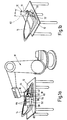
Fig. 3a um 90° gedrehter vergrößerter Darstellung. - Die in der Zeichnung dargestellte Roboteranordnung 10 ist vor allem zur Versiegelung von verklebten Bördelnähten 12 von Kraftfahrzeugteilen 14 bestimmt. Der Roboter 10 trägt zu diesem Zweck an seinem Endglied 16 einen Düsenkopf 18, der über einen flexiblen Schlauch mit einem Dichtstoff aus flüssigem oder pastösem Reaktionskunstharz beaufschlagbar ist und der eine mit einer Ventilnadel 22 verschließbare Auftragsdüse 24 aufweist. Die Betätigung der Ventilnadel 22 erfolgt über eine Zylinder-Kolbenanordnung 48, deren Kolben 50 in der Offenstellung über die Robotersteuerung entgegen der Kraft einer Schließfeder 51 pneumatisch nach oben und in der Schließstellung unter der Einwirkung der Schließfeder 51 nach unten verschoben wird.
- Der Düsenkopf ist über den Roboter relativ zur Unterlage 14 entlang einer vorgegebenen Bahn (Bördelrand 12) in Richtung des Pfeils 30 relativ zur Unterlage (KFZ-Teil 14) bewegbar und bringt über die Auftragsdüse einen Kunststoffstrang 32 auf die Unterlage 14 auf.
- Zu diesem Zweck weist der Düsenrand 28 an seinen in und entgegen der Bewegungsrichtung 30 weisenden Randpartien 34 je eine mit der Düsenöffnung 26 kommunizierende, zur Unterlage 14 hin randoffene formgebende Ausnehmung 36 auf, während er an seinen einander gegenüberliegenden, quer zur Bewegungsrichtung 30 weisenden Randpartien 38 gegen die Unterlage 14 andrückbar ist. Um Unebenheiten auf der Unterlage entlang der Bewegungsbahn ausgleichen zu können, ist der Düsenkopf 18 um eine im Abstand von der Auftragsdüse 24 quer zur Bewegungsrichtung ausgerichtete Achse 40 schwenkbar am Endglied 16 der Roboteranordnung 10 angelenkt. Der Düsenkopf 18 weist zu diesem Zweck einen Ausleger 42 auf, mit der er an einem schräg nach unten über das Endglied 16 überstehenden Kragarm 44 angelenkt ist. Die Feder ist als zwischen dem Ausleger 42 und dem Kragarm 44 eingespannte Druckfeder 46 ausgebildet.
- Wie aus den
Fig. 1 und2 zu ersehen ist, ist am Endglied 16 des Roboters 10 zusätzlich eine UV-Lichtquelle 52 angeordnet, die sich in Bewegungsrichtung 30 hinter dem Düsenkopf 18 befindet, und die die Aufgabe hat, den Aushärtevorgang des auf der Unterlage 14 aufgetragenen Dichtstoffstrangs 32 fotochemisch zu aktivieren. - Die in
Fig. 1a und b gezeigte UV-Lichtquelle 52 ist in einem in Richtung Unterlage 14 offenen Lampengehäuse 54 angeordnet, das durch einen mit seinem Rand 56 gegen die Unterlage anlegbaren flexiblen Vorhang 58 begrenzt ist. Der Vorhang weist im Bereich seiner bezüglich der Bewegungsrichtung 30 vorderen und rückwärtigen Randpartie nicht dargestellte randoffene Ausnehmungen für den berührungsfreien Durchtritt des Dichtstoffstrangs 32 auf. Weiter ist in dem Lampengehäuse 54 eine das UV-Licht zu einer Applikationsstelle entlang der Bewegungsbahn lenkende Spiegelanordnung 60 vorgesehen. Wie ausFig. 1b zu ersehen ist, ist das Lampengehäuse 54 gegenüber einer Vertikalebene 62 um einen vorzugsweise über die Robotersteuerung einstellbaren Winkel α geneigt oder schwenkbar am Roboter-Endglied angeordnet. Außerdem ist es in Richtung der Doppelpfeile 64 vertikal heb- und senkbar am Endglied 16 befestigt. - Von der UV-Lichtquelle 52 ist zusätzlich ein Lichtwellenleiter 65 abgezweigt, der mit seiner Lichtaustrittsstelle in den Strömungsweg des flüssigen oder pastösen Kunststoffs innerhalb des Düsenkopfes 18 mündet. Mit dieser Maßnahme wird erreicht, daß das flüssige oder pastöse Kunststoffmaterial vor dem Austritt aus der Auftragsdüse 24 bereits fotochemisch aktiviert wird, so daß die Härtungsreaktion während oder alsbald nach dem Auftrag auf den Bördelrand 12 einsetzen kann.
- Bei der in
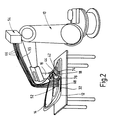
Fig. 2 gezeigten Ausführungsvariante besteht die UV-Lichtquelle 52 aus einer in größerem Abstand vom Endglied 16 auf der Roboteranordnung 10 angeordnetem Lampengehäuse 54 mit mindestens einer UV-Lampe sowie mehreren vom Lampengehäuse 54 zu einem endgliedfesten Halter 68 geführten Lichtwellenleitern 66. Die Lichtaustrittsstellen der Lichtwellenleitern 66 weisen nach unten in Richtung Bördelrand 12. Sie sind in Bewegungsrichtung hinter dem Düsenkopf 18 hintereinander an dem Halter 68 fixiert. - Bei den Ausführungsbeispielen nach
Fig. 2 und3a ist zusätzlich eine Heizvorrichtung zur Aufheizung des zugleich thermisch aktivierbaren Kunststoffs vorgesehen. Die Heizvorrichtung weist dabei ein im Düsenkopf angeordnetes Heizelement 70 auf, das elektrisch aufheizbar ist und über das das vorbeiströmende Kunststoffmaterial auf eine erhöhte Temperatur gebracht und thermisch aktiviert wird. - Weiter ist an der in
Fig. 2 gezeigten Roboteranordnung ein Heizaggregat angeordnet, das zwei in Richtung Unterlage weisende, beispielsweise als Infrarotheizer oder Heißluftdüsen ausgebildete Heizelemente 74,76 aufweist. Das Heizelement 74 ist dabei in Bewegungsrichtung vor der Auftragsdüse 24 angeordnet. Es heizt die Unterlage 14 im Bereich des Bördelrands 12 vor, damit der Klebstoffstrang beim Auftreffen auf die Unterlage aufgeheizt und thermisch aktiviert wird. Das Heizelement 76 ist in Bewegungsrichtung hinter der Auftragsdüse angeordnet und auf den bereits aufgetragenen Klebstoffstrang gerichtet. - Grundsätzlich ist es auch möglich, die Unterlage im Bereich der Bewegungsbahn induktiv aufzuheizen.
- Zusammenfassend ist folgendes festzuhalten: Die Erfindung bezieht sich auf eine Vorrichtung und ein Verfahren zum Aufbringen eines Klebstoffstrangs auf eine Unterlage. Die Vorrichtung und das Verfahren sind beispielsweise in der Autoindustrie zum Versiegeln von Bördelnähten 12 an Blechteilen 14 bestimmt. Die Vorrichtung umfaßt einen vorzugsweise am Endglied 16 einer Roboteranordnung 10 befestigbaren, relativ zur Unterlage 14 entlang einer vorgegebenen Bahn 12 bewegbaren Düsenkopf 18, der mit einem aushärtbaren flüssigen oder pastösen Kunststoff unter Druck beaufschlagbar ist und der eine vorzugsweise mit einer Ventilnadel 22 verschließbare Auftragsdüse 24 aufweist. Um eine blasenfreie Aushärtung zu ermöglichen, wird gemäß der Erfindung eine UV-Lichtquelle zur fotochemischen Aktivierung des Kunststoffs vorgeschlagen, die mindestens eine am Endglied 16 angeordnete, in Bewegungsrichtung hinter dem Düsenkopf 18 in Richtung Unterlage 14 weisende Lichtaustrittsstelle oder alternativ dazu mindestens eine vor der Auftragsdüse 24 in den Strömungsweg des flüssigen oder pastösen Kunststoffs mündende Lichtaustrittsstelle aufweist.
Claims (31)
- Vorrichtung zum Aufbringen eines Kunststoffstrangs auf eine Unterlage mit einem mit einem verfestigten flüssigen oder pastösen Kunststoff unter Druck beaufschlagbaren Düsenkopf (18), der eine vorzugsweise verschließbare Auftragsdüse (24) aufweist, wobei Düsenkopf (18) und Unterlage (14) mittels einer Roboteranordnung (10) so relativ zueinander bewegbar sind, daß die Auftragsdüse (24) entlang einer vorgegebenen Bahn (12) entlang der Unterlage (14) geführt ist, gekennzeichnet durch, eine UV-Lichtquelle (52) zur fotochemischen Aktivierung des Kunststoffs, die mindestens eine in Richtung Unterlage (14) und/oder in Richtung aus dem Düsenkopf (18) ausgebrachtem Kunststoff weisende Lichtaustrittsstelle aufweist, wobei die UV-Lichtquelle (52), mindestens eine in Bewegungsrichtung hinter dem Düsenkopf (18) angeordneten, in den Strömungsweg des flüssigen oder pastösen Kunststoffs mündende Lichtaustrittsstelle aufweist.
- Vorrichtung nach Anspruch 1, dadurch gekennzeichnet, daß der Düsenkopf (18) am Endglied (16) der Roboteranordnung (10) angeordnet und mit dieser relativ zur Unterlage (14) entlang der vorgegebenen Bahn (12) bewegbar ist.
- Vorrichtung nach einem der vorhergehenden Ansprüche, dadurch gekennzeichnet, daß die UV-Lichtquelle (52) an der Roboteranordnung (10) oder am Düsenkopf (18) angeordnet und optisch mit der Lichtaustrittsstelle verbunden ist.
- Vorrichtung nach einem der Ansprüche 1 bis 3, dadurch gekennzeichnet, daß die UV-Lichtquelle über mindestens einen Lichtwellenleiter (65,66) mit der mindestens einen Lichtaustrittsstelle verbunden ist.
- Vorrichtung nach einem der Ansprüche 1 bis 4, dadurch gekennzeichnet, daß die UV-Lichtquelle (52) in einem in Richtung Unterlage und/oder in Richtung aus dem Düsenkopf (18) ausgebrachtem Kunststoff offenen Lampengehäuse (54) angeordnet ist.
- Vorrichtung nach Anspruch 5, dadurch gekennzeichnet, daß in dem Lampengehäuse (54) eine das UV-Licht zu einer Applikationsstelle entlang der Bewegungsbahn (12) lenkende Spiegelanordnung (60) angeordnet ist.
- Vorrichtung nach Anspruch 5 oder 6, dadurch gekennzeichnet, daß das Lampengehäuse (54) durch einen mit seinem Rand (56) gegen die Unterlage (14) anlegbaren, flexiblen Vorhang (58) begrenzt ist.
- Vorrichtung nach Anspruch 7, dadurch gekennzeichnet, daß der Vorhang (58) an seinem in Bewegungsrichtung (30) vorderen und rückwärtigen Randpartien eine randoffene Ausnehmung aufweist.
- Vorrichtung nach Anspruch 4, dadurch gekennzeichnet, daß die UV-Lichtquelle (52) eine von der UV-Lampe zur Lichtaustrittsstelle geführte flexible Lichtwellenleiteranordnung (66) aufweist.
- Vorrichtung nach Anspruch 9, dadurch gekennzeichnet, daß die Lichtwellenleiteranordnung mehrere Lichtwellenleiter (66) umfaßt, deren zur Unterlage (14) weisende Lichtaustrittsöffnungen in Bewegungsrichtung des Düsenkopfes (18) überwiegend hintereinander angeordnet sind.
- Vorrichtung nach einem der Ansprüche 1 bis 10, gekennzeichnet durch mindestens einen Lichtwellenleiter (65), der von der UV-Lichtquelle zu einer Lichtaustrittsstelle innerhalb des Düsenkopfes (18) führt.
- Vorrichtung nach einem der Ansprüche 1 bis 11, gekennzeichnet durch eine Heizvorrichtung zur Aufheizung des Kunststoffs.
- Vorrichtung nach Anspruch 12, dadurch gekennzeichnet, daß die Heizvorrichtung ein im Düsenkopf (18) angeordnetes Heizelement aufweist.
- Vorrichtung nach Anspruch 12 oder 13, dadurch gekennzeichnet, daß die Heizvorrichtung ein vorzugsweise an der Roboteranordnung (10) angeordnetes Heißluftgebläse aufweist.
- Vorrichtung nach einem der Ansprüche 12 bis 14, dadurch gekennzeichnet, daß die Heizvorrichtung mindestens ein vorzugsweise am Endglied (16) der Roboteranordnung (10) angeordnetes, in Richtung Unterlage (14) weisendes Heizelement (74,76) aufweist.
- Vorrichtung nach Anspruch 15, dadurch gekennzeichnet, daß das mindestens eine Heizelement (74) in Bewegungsrichtung hinter der Auftragsdüse (24) angeordnet ist.
- Vorrichtung nach Anspruch 15 oder 16, dadurch gekennzeichnet, daß das mindestens eine Heizelement (74) in Bewegungsrichtung (30) vor der Auftragsdüse (24) angeordnet ist.
- Vorrichtung nach einem der Ansprüche 15 bis 17, dadurch gekennzeichnet, daß das Heizelement (74,76) aus der Gruppe Heißluftdüse, IR- oder NIR-Heizer ausgebildet ist.
- Vorrichtung nach einem der Ansprüche 12 bis 18, dadurch gekennzeichnet, daß die Heizvorrichtung ein die Unterlage (14) zumindest entlang der Bewegungsbahn (12) aufheizendes Heizaggregat aufweist.
- Vorrichtung nach Anspruch 19, dadurch gekennzeichnet, daß das Heizaggregat als Induktionsheizer ausgebildet ist.
- Verfahren zum Aufbringen eines Kunststoffstrangs auf eine Unterlage, bei welchem der Kunststoff in flüssigem oder pastösem Zustand aus einer entlang der Unterlage geführten Düse auf die Unterlage aufgetragen und dort verfestigt wird, dadurch gekennzeichnet, daß der flüssige oder pastöse Kunststoff unmittelbar vor und/oder unmittelbar nach dem Auftrag auf die Unterlage mit UV-Licht bestrahlt und dabei fotochemisch zum Verfestigen aktiviert wird, wobei das UV-Licht aus einer in Bewegungsrichtung hinter der Düse angeordneten Lichtaustrittsstelle auf den flüssigen oder pastösen Kunststoff gerichtet wird und das UV-Licht mit der Düse geführt wird.
- Verfahren nach Anspruch 21, dadurch gekennzeichnet, daß der flüssige oder pastöse Kunststoff im Durchlauf entlang einem Strömungsweg mit dem UV-Licht bestrahlt wird.
- Verfahren nach Anspruch 22, dadurch gekennzeichnet, daß das UV-Licht über ein Lichtfenster in den Strömungsweg des flüssigen oder pastösen Kunststoffs eingeleitet wird.
- Verfahren nach Anspruch 23, dadurch gekennzeichnet, daß das Lichtfenster durch den vorbeiströmenden flüssigen oder pastösen Kunststoff benetzt und gereinigt wird.
- Verfahren nach einem der Ansprüche 22 bis 24, dadurch gekennzeichnet, daß das UV-Licht über einen Lichtwellenleiter zur Lichtaustrittsstelle geleitet wird.
- Verfahren nach einem der Ansprüche 21 bis 25, dadurch gekennzeichnet, daß der flüssige oder pastöse Kunststoff durch eine entlang einer Bewegungsbahn der Düse geführte UV-Lichtquelle im Vorbeibewegen mit UV-Licht bestrahlt wird.
- Verfahren nach einem der Ansprüche 21 bis 26, dadurch gekennzeichnet, daß der flüssige oder pastöse Kunststoff im erwärmten Zustand mit UV-Licht bestrahlt wird.
- Verfahren nach einem der Ansprüche 21 bis 27, dadurch gekennzeichnet, daß der flüssige oder pastöse Kunststoff vor dem Auftrag auf die Unterlage aufgeheizt wird.
- Verfahren nach einem der Ansprüche 21 bis 28, dadurch gekennzeichnet, daß der flüssige oder pastöse Kunststoff auf eine zumindest im Bereich der Bewegungsbahn vorgeheizte Unterlage aufgetragen und dabei aufgeheizt wird.
- Verwendung der Vorrichtung nach einem der Ansprüche 1 bis 20 und des Verfahrens nach einem der Ansprüche 23 bis 29 zum Aufbringen eines Dichtstoffs auf eine Bördelnaht an zwei Blechteilen.
- Verwendung nach Anspruch 30, dadurch gekennzeichnet, daß sich zwischen den Blechteilen im Bereich der Bördelnaht ein vorzugsweise thermisch verfestigbarer Klebstoff befindet.
Applications Claiming Priority (2)
| Application Number | Priority Date | Filing Date | Title |
|---|---|---|---|
| DE19936730 | 1999-08-06 | ||
| DE19936730A DE19936730A1 (de) | 1999-08-06 | 1999-08-06 | Vorrichtung und Verfahren zum Aufbringen eines Kunststoffstrangs auf eine Unterlage |
Publications (3)
| Publication Number | Publication Date |
|---|---|
| EP1074307A2 EP1074307A2 (de) | 2001-02-07 |
| EP1074307A3 EP1074307A3 (de) | 2004-03-17 |
| EP1074307B1 true EP1074307B1 (de) | 2008-06-11 |
Family
ID=7917179
Family Applications (1)
| Application Number | Title | Priority Date | Filing Date |
|---|---|---|---|
| EP00115013A Expired - Lifetime EP1074307B1 (de) | 1999-08-06 | 2000-07-24 | Vorrichtung und Verfahren zum Aufbringen eines Kunststoffstrangs auf eine Unterlage |
Country Status (3)
| Country | Link |
|---|---|
| EP (1) | EP1074307B1 (de) |
| AT (1) | ATE397979T1 (de) |
| DE (2) | DE19936730A1 (de) |
Cited By (2)
| Publication number | Priority date | Publication date | Assignee | Title |
|---|---|---|---|---|
| DE102018003345A1 (de) | 2018-04-23 | 2019-10-24 | Kienle + Spiess Gmbh | Verfahren zur Herstellung von Lamellenpaketen sowie Auftrageinrichtung für ein Klebemittel zur Durchführung des Verfahrens |
| DE102018102238B4 (de) | 2018-02-01 | 2022-06-23 | Dr. Ing. H.C. F. Porsche Aktiengesellschaft | Verfahren zum Verkleben und Abdichten von Naht- und Fügestellen und Anwendung eines Verfahrens |
Families Citing this family (10)
| Publication number | Priority date | Publication date | Assignee | Title |
|---|---|---|---|---|
| DE10020679A1 (de) * | 2000-04-27 | 2001-11-08 | Basf Coatings Ag | Verfahren und Vorrichtung zum Abdichten von Fugen und Nähten in Kraftfahrzeugkarosserien |
| DE10141413B4 (de) * | 2001-08-23 | 2005-10-06 | Dannenhauer, Fritz, Dr. | Vorrichtung und Verfahren zur Applikation von Lacken mit energetisch initiierter Aushärtung |
| DE102005050135B4 (de) * | 2005-10-18 | 2016-09-29 | Sca Schucker Gmbh & Co. Kg | Materialauftragsvorrichtung für Reaktionsgemische |
| JP2010503523A (ja) * | 2006-09-18 | 2010-02-04 | インペリアル ケミカル インダストリーズ ピーエルーシー | 膜の形成および評価 |
| DE102007010636A1 (de) * | 2007-03-02 | 2008-10-30 | Intec Gmbh Lackiersysteme | Anlage zum Beschichten von Werkstücken insbesondere Lackieranlage |
| US9339832B2 (en) | 2012-03-22 | 2016-05-17 | Basf Se | Spraygun for producing cured coating films and methods of use thereof |
| EP2828001A1 (de) * | 2012-03-22 | 2015-01-28 | Basf Se | Verfahren und vorrichtung zur herstellung von gehärteten lackschichten |
| DE102013203302B4 (de) * | 2013-02-27 | 2015-02-19 | Henkel Ag & Co. Kgaa | Verfahren zum Herstellen einer Versiegelung und dessen Verwendung |
| CN109590147B (zh) * | 2019-01-04 | 2023-11-21 | 福耀集团长春有限公司 | 一种汽车玻璃托架自动供料涂胶系统 |
| CN113522662B (zh) * | 2021-06-11 | 2023-12-05 | 张安娜 | 一种智慧社区相关led晶片贴片工件涂蜡处理装置 |
Family Cites Families (14)
| Publication number | Priority date | Publication date | Assignee | Title |
|---|---|---|---|---|
| EP0094915B1 (de) * | 1982-05-19 | 1987-01-21 | Ciba-Geigy Ag | Härtbare, Metallocenkomplexe enthaltende Zusammensetzungen, daraus erhältliche aktivierte Vorstufen und deren Verwendung |
| DD259157A1 (de) * | 1986-04-01 | 1988-08-17 | Werkzeugmasch Forschzent | Schmelzklebe- und schweissvorrichtung |
| DE3737455A1 (de) * | 1986-11-06 | 1988-05-19 | Westinghouse Electric Corp | Einrichtung und verfahren zum erzeugen von farbmustern |
| DE3702999C2 (de) * | 1987-02-02 | 2003-03-06 | Siemens Ag | Vorrichtung zur Verarbeitung von UV-härtbaren Reaktionsharzmassen und deren Anwendung |
| DE3800628A1 (de) * | 1987-09-15 | 1989-03-23 | Schaft Volker | Verfahren und vorrichtung zum haerten von auf einem koerper aufgetragenen schichten |
| DE3809756C2 (de) * | 1988-03-23 | 1996-02-29 | Hoerauf Michael Maschf | Vorrichtung zum Auftragen von Klebstoff auf einen Behältermantel |
| IL88886A (en) * | 1989-01-05 | 1993-02-21 | Tamglass Oy | Method and system for applying a painted border around a windshield plate |
| DE3900861A1 (de) * | 1989-01-13 | 1990-07-19 | Ribnitz Peter | Verfahren zum herstellen einer dichtenden verbindungsrandpartie |
| DE3909688A1 (de) * | 1989-03-23 | 1990-09-27 | Espe Stiftung | Verfahren zum kleben oder vergiessen von substraten und vorrichtung zur seiner durchfuehrung |
| JP2669272B2 (ja) * | 1992-06-03 | 1997-10-27 | 信越化学工業株式会社 | 立体模様形成方法 |
| US5474799A (en) * | 1992-10-13 | 1995-12-12 | Reliance Electric Industrial Company | Apparatus and method for coating an electromagnetic coil |
| DE29517958U1 (de) * | 1995-11-13 | 1997-03-20 | Ernst Mühlbauer KG, 22547 Hamburg | Gerät für den inkrementalen Aufbau einer Zahnfüllung |
| DE19545800C2 (de) * | 1995-12-08 | 1997-10-23 | Int Schuh Maschinen Co Gmbh | Klebstoff-Auftragvorrichtung |
| US5948194A (en) * | 1998-06-12 | 1999-09-07 | Ford Global Technologies, Inc. | In-line microwave heating of adhesives |
-
1999
- 1999-08-06 DE DE19936730A patent/DE19936730A1/de not_active Withdrawn
-
2000
- 2000-07-24 DE DE50015197T patent/DE50015197D1/de not_active Expired - Lifetime
- 2000-07-24 EP EP00115013A patent/EP1074307B1/de not_active Expired - Lifetime
- 2000-07-24 AT AT00115013T patent/ATE397979T1/de not_active IP Right Cessation
Cited By (5)
| Publication number | Priority date | Publication date | Assignee | Title |
|---|---|---|---|---|
| DE102018102238B4 (de) | 2018-02-01 | 2022-06-23 | Dr. Ing. H.C. F. Porsche Aktiengesellschaft | Verfahren zum Verkleben und Abdichten von Naht- und Fügestellen und Anwendung eines Verfahrens |
| DE102018003345A1 (de) | 2018-04-23 | 2019-10-24 | Kienle + Spiess Gmbh | Verfahren zur Herstellung von Lamellenpaketen sowie Auftrageinrichtung für ein Klebemittel zur Durchführung des Verfahrens |
| US11535021B2 (en) * | 2018-04-23 | 2022-12-27 | Kienle + Spiess Gmbh | Method for producing lamination stacks and application device for an adhesive for performing the method |
| US20230089960A1 (en) * | 2018-04-23 | 2023-03-23 | Kienle + Spiess Gmbh | Method for Producing Lamination Stacks and Application Device for an Adhesive for Performing the Method |
| US12447729B2 (en) * | 2018-04-23 | 2025-10-21 | Feintool International Holding Ag | Method for producing lamination stacks and application device for an adhesive for performing the method |
Also Published As
| Publication number | Publication date |
|---|---|
| DE50015197D1 (de) | 2008-07-24 |
| ATE397979T1 (de) | 2008-07-15 |
| EP1074307A2 (de) | 2001-02-07 |
| DE19936730A1 (de) | 2001-02-22 |
| EP1074307A3 (de) | 2004-03-17 |
Similar Documents
| Publication | Publication Date | Title |
|---|---|---|
| EP1074307B1 (de) | Vorrichtung und Verfahren zum Aufbringen eines Kunststoffstrangs auf eine Unterlage | |
| DE10038158C5 (de) | Verfahren und Vorrichtung zum Verbinden von Gegenständen mittels plastisch verformbarer Verbindungskörper | |
| DE10332939B4 (de) | Vorrichtung zum Reinigen eines Frontbereiches vor einem in einem Kraftfahrzeug eingebauten Abstandssensors | |
| EP2952316B1 (de) | Faserauftragwerkzeug, faserverlegevorrichtung, faserverlegeverfahren und herstellverfahren | |
| DE102010052206A1 (de) | Vorrichtung zum Herstellen von dreidimensionalen Objekten | |
| DE2347189A1 (de) | Vorrichtung zur verhinderung der ansammlung eines dichtungsmittels an einer das dichtungsmittel intermittierend ausstossenden duese | |
| DE102004039684B4 (de) | Vorrichtung zur Aufbringung einer Leitpaste auf eine gekrümmte Harzglasscheibe | |
| WO2016151038A1 (de) | Aktivierungseinrichtung für eine vorrichtung zur aufbringung von insbesondere kleberlos wärmeaktivierbaren kantenstreifen auf plattenartige werkstücke | |
| DE3718625C2 (de) | ||
| EP3222407B1 (de) | Schweissautomat | |
| EP0642407B1 (de) | Verfahren und vorrichtung zum biegen von kunststoffrohren | |
| DE19936716A1 (de) | Verfahren und Vorrichtung zum Auftragen eines Kunststoffstrangs auf eine Unterlage | |
| EP2658703B1 (de) | Verfahren und vorrichtung zur herstellung eines bauteils mittels spritzgiessens und schweissens | |
| WO1990005059A1 (de) | Verfahren und vorrichtung zum aufschweissen eines thermoplastischen abdeckbandes | |
| DE19941996A1 (de) | Verfahren und Anordnung zum Aufheizen eines Bauteils entlang einer vorgegebenen Bahn | |
| DE202015005290U1 (de) | Düsenanordnung | |
| DE9420596U1 (de) | Umbugvorrichtung für Verkleidungsteile | |
| DE102018125609A1 (de) | Verfahren und Vorrichtung zum Befestigen einer Kantenleiste | |
| DE29507067U1 (de) | Vorrichtung zum kleberfreien Umbug von Verkleidungsteilen | |
| EP0560171A1 (de) | Frei programmierbares Auftragsgerät für Medien wie Dichtmasse, Kleber etc. | |
| EP0559106B1 (de) | Auftragsgerät für Medien wie Kleber, Dichtmasse etc. | |
| DE19545800C2 (de) | Klebstoff-Auftragvorrichtung | |
| DE10257112A1 (de) | Laserstrahlbearbeitungsvorrichtung zum Fügen und/oder Beschichten von Kunststoffen | |
| DE102007031555A1 (de) | Reinigungsvorrichtung für eine Sprühvorrichtung | |
| DE10312381A1 (de) | Verfahren zur Trocknung einer Lackierung auf einem Objekt |
Legal Events
| Date | Code | Title | Description |
|---|---|---|---|
| PUAI | Public reference made under article 153(3) epc to a published international application that has entered the european phase |
Free format text: ORIGINAL CODE: 0009012 |
|
| AK | Designated contracting states |
Kind code of ref document: A2 Designated state(s): AT BE CH CY DE DK ES FI FR GB GR IE IT LI LU MC NL PT SE |
|
| AX | Request for extension of the european patent |
Free format text: AL;LT;LV;MK;RO;SI |
|
| RAP1 | Party data changed (applicant data changed or rights of an application transferred) |
Owner name: SCA SCHUCKER GMBH & CO. Owner name: VOLKSWAGEN AKTIENGESELLSCHAFT |
|
| RAP1 | Party data changed (applicant data changed or rights of an application transferred) |
Owner name: VOLKSWAGEN AKTIENGESELLSCHAFT Owner name: SCA SCHUCKER GMBH |
|
| RAP1 | Party data changed (applicant data changed or rights of an application transferred) |
Owner name: SCA SCHUCKER GMBH & CO. Owner name: VOLKSWAGEN AKTIENGESELLSCHAFT |
|
| PUAL | Search report despatched |
Free format text: ORIGINAL CODE: 0009013 |
|
| AK | Designated contracting states |
Kind code of ref document: A3 Designated state(s): AT BE CH CY DE DK ES FI FR GB GR IE IT LI LU MC NL PT SE |
|
| AX | Request for extension of the european patent |
Extension state: AL LT LV MK RO SI |
|
| 17P | Request for examination filed |
Effective date: 20040917 |
|
| AKX | Designation fees paid |
Designated state(s): AT BE CH CY DE DK ES FI FR GB GR IE IT LI LU MC NL PT SE |
|
| 17Q | First examination report despatched |
Effective date: 20070417 |
|
| GRAP | Despatch of communication of intention to grant a patent |
Free format text: ORIGINAL CODE: EPIDOSNIGR1 |
|
| GRAS | Grant fee paid |
Free format text: ORIGINAL CODE: EPIDOSNIGR3 |
|
| GRAA | (expected) grant |
Free format text: ORIGINAL CODE: 0009210 |
|
| AK | Designated contracting states |
Kind code of ref document: B1 Designated state(s): AT BE CH CY DE DK ES FI FR GB GR IE IT LI LU MC NL PT SE |
|
| REG | Reference to a national code |
Ref country code: GB Ref legal event code: FG4D Free format text: NOT ENGLISH |
|
| REG | Reference to a national code |
Ref country code: CH Ref legal event code: EP |
|
| REF | Corresponds to: |
Ref document number: 50015197 Country of ref document: DE Date of ref document: 20080724 Kind code of ref document: P |
|
| REG | Reference to a national code |
Ref country code: IE Ref legal event code: FG4D Free format text: LANGUAGE OF EP DOCUMENT: GERMAN |
|
| PG25 | Lapsed in a contracting state [announced via postgrant information from national office to epo] |
Ref country code: FI Free format text: LAPSE BECAUSE OF FAILURE TO SUBMIT A TRANSLATION OF THE DESCRIPTION OR TO PAY THE FEE WITHIN THE PRESCRIBED TIME-LIMIT Effective date: 20080611 |
|
| PG25 | Lapsed in a contracting state [announced via postgrant information from national office to epo] |
Ref country code: NL Free format text: LAPSE BECAUSE OF FAILURE TO SUBMIT A TRANSLATION OF THE DESCRIPTION OR TO PAY THE FEE WITHIN THE PRESCRIBED TIME-LIMIT Effective date: 20080611 |
|
| NLV1 | Nl: lapsed or annulled due to failure to fulfill the requirements of art. 29p and 29m of the patents act | ||
| PG25 | Lapsed in a contracting state [announced via postgrant information from national office to epo] |
Ref country code: ES Free format text: LAPSE BECAUSE OF FAILURE TO SUBMIT A TRANSLATION OF THE DESCRIPTION OR TO PAY THE FEE WITHIN THE PRESCRIBED TIME-LIMIT Effective date: 20080922 Ref country code: PT Free format text: LAPSE BECAUSE OF FAILURE TO SUBMIT A TRANSLATION OF THE DESCRIPTION OR TO PAY THE FEE WITHIN THE PRESCRIBED TIME-LIMIT Effective date: 20081111 Ref country code: SE Free format text: LAPSE BECAUSE OF FAILURE TO SUBMIT A TRANSLATION OF THE DESCRIPTION OR TO PAY THE FEE WITHIN THE PRESCRIBED TIME-LIMIT Effective date: 20080911 |
|
| REG | Reference to a national code |
Ref country code: IE Ref legal event code: FD4D |
|
| REG | Reference to a national code |
Ref country code: CH Ref legal event code: PL |
|
| PG25 | Lapsed in a contracting state [announced via postgrant information from national office to epo] |
Ref country code: MC Free format text: LAPSE BECAUSE OF NON-PAYMENT OF DUE FEES Effective date: 20080731 |
|
| PLBE | No opposition filed within time limit |
Free format text: ORIGINAL CODE: 0009261 |
|
| STAA | Information on the status of an ep patent application or granted ep patent |
Free format text: STATUS: NO OPPOSITION FILED WITHIN TIME LIMIT |
|
| PG25 | Lapsed in a contracting state [announced via postgrant information from national office to epo] |
Ref country code: DK Free format text: LAPSE BECAUSE OF FAILURE TO SUBMIT A TRANSLATION OF THE DESCRIPTION OR TO PAY THE FEE WITHIN THE PRESCRIBED TIME-LIMIT Effective date: 20080611 Ref country code: IE Free format text: LAPSE BECAUSE OF FAILURE TO SUBMIT A TRANSLATION OF THE DESCRIPTION OR TO PAY THE FEE WITHIN THE PRESCRIBED TIME-LIMIT Effective date: 20080611 |
|
| 26N | No opposition filed |
Effective date: 20090312 |
|
| GBPC | Gb: european patent ceased through non-payment of renewal fee |
Effective date: 20080911 |
|
| PG25 | Lapsed in a contracting state [announced via postgrant information from national office to epo] |
Ref country code: CH Free format text: LAPSE BECAUSE OF NON-PAYMENT OF DUE FEES Effective date: 20080731 Ref country code: LI Free format text: LAPSE BECAUSE OF NON-PAYMENT OF DUE FEES Effective date: 20080731 |
|
| REG | Reference to a national code |
Ref country code: FR Ref legal event code: ST Effective date: 20090529 |
|
| PG25 | Lapsed in a contracting state [announced via postgrant information from national office to epo] |
Ref country code: IT Free format text: LAPSE BECAUSE OF FAILURE TO SUBMIT A TRANSLATION OF THE DESCRIPTION OR TO PAY THE FEE WITHIN THE PRESCRIBED TIME-LIMIT Effective date: 20080611 |
|
| PG25 | Lapsed in a contracting state [announced via postgrant information from national office to epo] |
Ref country code: FR Free format text: LAPSE BECAUSE OF NON-PAYMENT OF DUE FEES Effective date: 20080731 Ref country code: AT Free format text: LAPSE BECAUSE OF NON-PAYMENT OF DUE FEES Effective date: 20080724 |
|
| PG25 | Lapsed in a contracting state [announced via postgrant information from national office to epo] |
Ref country code: GB Free format text: LAPSE BECAUSE OF NON-PAYMENT OF DUE FEES Effective date: 20080911 |
|
| PG25 | Lapsed in a contracting state [announced via postgrant information from national office to epo] |
Ref country code: LU Free format text: LAPSE BECAUSE OF NON-PAYMENT OF DUE FEES Effective date: 20080724 |
|
| PG25 | Lapsed in a contracting state [announced via postgrant information from national office to epo] |
Ref country code: BE Free format text: LAPSE BECAUSE OF NON-PAYMENT OF DUE FEES Effective date: 20080731 Ref country code: CY Free format text: LAPSE BECAUSE OF FAILURE TO SUBMIT A TRANSLATION OF THE DESCRIPTION OR TO PAY THE FEE WITHIN THE PRESCRIBED TIME-LIMIT Effective date: 20080611 |
|
| PG25 | Lapsed in a contracting state [announced via postgrant information from national office to epo] |
Ref country code: GR Free format text: LAPSE BECAUSE OF FAILURE TO SUBMIT A TRANSLATION OF THE DESCRIPTION OR TO PAY THE FEE WITHIN THE PRESCRIBED TIME-LIMIT Effective date: 20080912 |
|
| REG | Reference to a national code |
Ref country code: DE Ref legal event code: R081 Ref document number: 50015197 Country of ref document: DE Owner name: VOLKSWAGEN AKTIENGESELLSCHAFT, DE Free format text: FORMER OWNER: SCA SCHUCKER GMBH & CO., VOLKSWAGEN AKTIENGESELLSCHAFT, , DE Effective date: 20110221 Ref country code: DE Ref legal event code: R081 Ref document number: 50015197 Country of ref document: DE Owner name: VOLKSWAGEN AKTIENGESELLSCHAFT, DE Free format text: FORMER OWNERS: SCA SCHUCKER GMBH & CO., 75015 BRETTEN, DE; VOLKSWAGEN AKTIENGESELLSCHAFT, 38440 WOLFSBURG, DE Effective date: 20110221 |
|
| PGFP | Annual fee paid to national office [announced via postgrant information from national office to epo] |
Ref country code: DE Payment date: 20160731 Year of fee payment: 17 |
|
| REG | Reference to a national code |
Ref country code: DE Ref legal event code: R119 Ref document number: 50015197 Country of ref document: DE |
|
| PG25 | Lapsed in a contracting state [announced via postgrant information from national office to epo] |
Ref country code: DE Free format text: LAPSE BECAUSE OF NON-PAYMENT OF DUE FEES Effective date: 20180201 |