EP1073838B1 - Brennstoffeinspritzventil - Google Patents
Brennstoffeinspritzventil Download PDFInfo
- Publication number
- EP1073838B1 EP1073838B1 EP99957949A EP99957949A EP1073838B1 EP 1073838 B1 EP1073838 B1 EP 1073838B1 EP 99957949 A EP99957949 A EP 99957949A EP 99957949 A EP99957949 A EP 99957949A EP 1073838 B1 EP1073838 B1 EP 1073838B1
- Authority
- EP
- European Patent Office
- Prior art keywords
- valve
- swirl
- fuel injection
- valve seat
- inclination
- Prior art date
- Legal status (The legal status is an assumption and is not a legal conclusion. Google has not performed a legal analysis and makes no representation as to the accuracy of the status listed.)
- Expired - Lifetime
Links
- 239000000446 fuel Substances 0.000 title claims description 60
- 238000002347 injection Methods 0.000 title claims description 31
- 239000007924 injection Substances 0.000 title claims description 31
- 238000002485 combustion reaction Methods 0.000 claims description 16
- 238000011144 upstream manufacturing Methods 0.000 claims description 7
- 238000007373 indentation Methods 0.000 claims 3
- 239000007921 spray Substances 0.000 description 14
- 238000009826 distribution Methods 0.000 description 8
- 230000033001 locomotion Effects 0.000 description 5
- 239000002245 particle Substances 0.000 description 5
- 239000000243 solution Substances 0.000 description 5
- 238000001125 extrusion Methods 0.000 description 3
- 238000009434 installation Methods 0.000 description 2
- 238000000034 method Methods 0.000 description 2
- 238000005507 spraying Methods 0.000 description 2
- 238000000889 atomisation Methods 0.000 description 1
- 239000003795 chemical substances by application Substances 0.000 description 1
- 230000008021 deposition Effects 0.000 description 1
- 238000011161 development Methods 0.000 description 1
- 230000018109 developmental process Effects 0.000 description 1
- 238000009760 electrical discharge machining Methods 0.000 description 1
- 238000005538 encapsulation Methods 0.000 description 1
- 230000005284 excitation Effects 0.000 description 1
- 238000001914 filtration Methods 0.000 description 1
- 238000000227 grinding Methods 0.000 description 1
- 238000005304 joining Methods 0.000 description 1
- 238000003698 laser cutting Methods 0.000 description 1
- 238000010329 laser etching Methods 0.000 description 1
- 238000004519 manufacturing process Methods 0.000 description 1
- 239000002184 metal Substances 0.000 description 1
- 230000035515 penetration Effects 0.000 description 1
- 230000002093 peripheral effect Effects 0.000 description 1
- 230000036316 preload Effects 0.000 description 1
- 238000003825 pressing Methods 0.000 description 1
- 238000004080 punching Methods 0.000 description 1
- 238000007789 sealing Methods 0.000 description 1
- 238000005476 soldering Methods 0.000 description 1
- 238000003466 welding Methods 0.000 description 1
- 238000004804 winding Methods 0.000 description 1
Images



Classifications
-
- F—MECHANICAL ENGINEERING; LIGHTING; HEATING; WEAPONS; BLASTING
- F02—COMBUSTION ENGINES; HOT-GAS OR COMBUSTION-PRODUCT ENGINE PLANTS
- F02M—SUPPLYING COMBUSTION ENGINES IN GENERAL WITH COMBUSTIBLE MIXTURES OR CONSTITUENTS THEREOF
- F02M61/00—Fuel-injectors not provided for in groups F02M39/00 - F02M57/00 or F02M67/00
- F02M61/16—Details not provided for in, or of interest apart from, the apparatus of groups F02M61/02 - F02M61/14
-
- F—MECHANICAL ENGINEERING; LIGHTING; HEATING; WEAPONS; BLASTING
- F02—COMBUSTION ENGINES; HOT-GAS OR COMBUSTION-PRODUCT ENGINE PLANTS
- F02M—SUPPLYING COMBUSTION ENGINES IN GENERAL WITH COMBUSTIBLE MIXTURES OR CONSTITUENTS THEREOF
- F02M61/00—Fuel-injectors not provided for in groups F02M39/00 - F02M57/00 or F02M67/00
- F02M61/16—Details not provided for in, or of interest apart from, the apparatus of groups F02M61/02 - F02M61/14
- F02M61/18—Injection nozzles, e.g. having valve seats; Details of valve member seated ends, not otherwise provided for
- F02M61/1806—Injection nozzles, e.g. having valve seats; Details of valve member seated ends, not otherwise provided for characterised by the arrangement of discharge orifices, e.g. orientation or size
-
- F—MECHANICAL ENGINEERING; LIGHTING; HEATING; WEAPONS; BLASTING
- F02—COMBUSTION ENGINES; HOT-GAS OR COMBUSTION-PRODUCT ENGINE PLANTS
- F02M—SUPPLYING COMBUSTION ENGINES IN GENERAL WITH COMBUSTIBLE MIXTURES OR CONSTITUENTS THEREOF
- F02M51/00—Fuel-injection apparatus characterised by being operated electrically
- F02M51/06—Injectors peculiar thereto with means directly operating the valve needle
- F02M51/061—Injectors peculiar thereto with means directly operating the valve needle using electromagnetic operating means
- F02M51/0625—Injectors peculiar thereto with means directly operating the valve needle using electromagnetic operating means characterised by arrangement of mobile armatures
- F02M51/0664—Injectors peculiar thereto with means directly operating the valve needle using electromagnetic operating means characterised by arrangement of mobile armatures having a cylindrically or partly cylindrically shaped armature, e.g. entering the winding; having a plate-shaped or undulated armature entering the winding
- F02M51/0671—Injectors peculiar thereto with means directly operating the valve needle using electromagnetic operating means characterised by arrangement of mobile armatures having a cylindrically or partly cylindrically shaped armature, e.g. entering the winding; having a plate-shaped or undulated armature entering the winding the armature having an elongated valve body attached thereto
-
- F—MECHANICAL ENGINEERING; LIGHTING; HEATING; WEAPONS; BLASTING
- F02—COMBUSTION ENGINES; HOT-GAS OR COMBUSTION-PRODUCT ENGINE PLANTS
- F02M—SUPPLYING COMBUSTION ENGINES IN GENERAL WITH COMBUSTIBLE MIXTURES OR CONSTITUENTS THEREOF
- F02M61/00—Fuel-injectors not provided for in groups F02M39/00 - F02M57/00 or F02M67/00
- F02M61/16—Details not provided for in, or of interest apart from, the apparatus of groups F02M61/02 - F02M61/14
- F02M61/162—Means to impart a whirling motion to fuel upstream or near discharging orifices
-
- F—MECHANICAL ENGINEERING; LIGHTING; HEATING; WEAPONS; BLASTING
- F02—COMBUSTION ENGINES; HOT-GAS OR COMBUSTION-PRODUCT ENGINE PLANTS
- F02B—INTERNAL-COMBUSTION PISTON ENGINES; COMBUSTION ENGINES IN GENERAL
- F02B75/00—Other engines
- F02B75/12—Other methods of operation
- F02B2075/125—Direct injection in the combustion chamber for spark ignition engines, i.e. not in pre-combustion chamber
-
- Y—GENERAL TAGGING OF NEW TECHNOLOGICAL DEVELOPMENTS; GENERAL TAGGING OF CROSS-SECTIONAL TECHNOLOGIES SPANNING OVER SEVERAL SECTIONS OF THE IPC; TECHNICAL SUBJECTS COVERED BY FORMER USPC CROSS-REFERENCE ART COLLECTIONS [XRACs] AND DIGESTS
- Y02—TECHNOLOGIES OR APPLICATIONS FOR MITIGATION OR ADAPTATION AGAINST CLIMATE CHANGE
- Y02T—CLIMATE CHANGE MITIGATION TECHNOLOGIES RELATED TO TRANSPORTATION
- Y02T10/00—Road transport of goods or passengers
- Y02T10/10—Internal combustion engine [ICE] based vehicles
- Y02T10/12—Improving ICE efficiencies
Definitions
- the invention is based on a fuel injector according to the genus of claim 1, claim 4 and the Claim 7.
- the fuel injector according to the invention with the characterizing features of claim 1, claim 4 or of claim 7 has the advantage that in particular a simple way to compensate for the low cost with a desired inclination of an outlet opening resulting uneven distribution of fuel in the spray to be sprayed towards an even distribution of a sprayed at an angle is reached.
- the Fuel injector according to the invention is a very good atomization and a very precise spraying of the Fuel e.g. directly into a cylinder one Internal combustion engine reached. It will be special achieved even front of the hosed spray. In addition, single strands can be sprayed with large Avoid penetration depth and speed.
- valve seat in the Valve seat element swirling fuel on one extremely short flow path.
- This very short one Flow path is also guaranteed in that the Exit opening immediately at the end of the Valve seat surface avoiding any Collection rooms begin.
- the disc-shaped swirl element is very simple structured and therefore easy to shape.
- the Swirl element has the task of To generate rotary motion in the fuel. Since it is Swirl element is a single component, are in its Handling in the manufacturing process no restrictions expect.
- Opening area can be created that extends across the entire extends axial thickness of the swirl element and from one outer peripheral edge area is surrounded.
- Embodiments of the invention are in the drawing shown in simplified form and in the following Description explained in more detail.
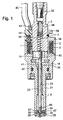
- 1 shows it Embodiment of a fuel injector
- figure 2 shows a section through the downstream valve end
- FIG. 3 a section along the line III-III in Figure 2
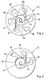
- Figure 4 a section along the line IV-IV in Figure 3 and thus a plan view of a swirl element as a first embodiment according to the invention
- Figure 5 shows a second Exemplary embodiment in a representation analogous to FIG. 4
- Figure 6 shows a third embodiment in a representation analogous to FIG. 2
- FIG. 7 a section along the line VII-VII in Figure 6, Figure 8
- Figure 9 another Embodiment of a valve needle tip and Figure 10 a Another embodiment of a valve needle tip.
- FIG. 1 for example, as a Embodiment shown electromagnetically actuatable valve in the form of an injection valve for Fuel injection systems from spark ignition systems
- Internal combustion engines have one of a magnetic coil 1 at least partially surrounded, as the inner pole of one Serving magnetic circuit, tubular, largely hollow cylindrical core 2.
- the fuel injector is particularly suitable as a high pressure injector for direct injection of fuel into a combustion chamber Internal combustion engine.
- a tiered one Spool 3 made of plastic takes a winding Magnetic coil 1 and allows in connection with the core 2 and an annular, non-magnetic, from the Magnetic coil 1 partially surrounded intermediate part 4 with a L-shaped cross section a particularly compact and short Structure of the injection valve in the area of the solenoid coil 1.
- the core 2 of the magnetic circuit also serves as Fuel inlet port, the longitudinal opening 7 a Represents fuel supply channel.
- an outer metal (e.g. ferritic) housing part 14 which as the outer pole or outer guide element closes the magnetic circuit and the Solenoid 1 completely at least in the circumferential direction surrounds.
- a fuel filter 15 is provided for the Filtering out such fuel components ensures that due to their size in the injector clogging or Can cause damage.
- the fuel filter 15 is z. B. fixed by pressing in the core 2.
- the core 2 forms with the housing part 14 that on the inlet side End of the fuel injector, with the top Housing part 14, for example in the axial direction seen just downstream via the magnetic coil 1 extends beyond.
- the upper housing part 14 closes tight and tight to a lower tubular housing part 18, the Z. B. consists of an axially movable valve part an armature 19 and a rod-shaped valve needle 20 or encloses an elongated valve seat support 21 or receives.
- the two housing parts 14 and 18 are, for. B. with a circumferential weld seam firmly connected.
- the valve seat support 21 has an internal one over its entire axial extent Through opening 24 which is concentric with the Longitudinal valve axis 8 runs.
- valve seat carrier 21 With its lower end 25, which also the downstream completion of the whole Fuel injector, surrounds the Valve seat carrier 21 in the through opening 24 fitted disc-shaped valve seat element 26 with a narrowing frustoconically downstream Valve seat surface 27.
- the through opening 24 In the through opening 24 is the z. B. rod-shaped, a largely circular Cross-sectioned valve needle 20 arranged on a valve closing section 28 at its downstream end having.
- This, for example, spherical or partial spherical or rounded or conical tapered valve closing section 28 acts in a known manner Way with that provided in the valve seat member 26 Valve seat surface 27 together.
- Outlet opening 32 Downstream of the Valve seat surface 27 is a in valve seat element 26 Outlet opening 32 introduced for the fuel.
- the injection valve is actuated in a known manner Way electromagnetic.
- a piezo actuator as excitable Actuator is also conceivable.
- actuation via a controlled pressure-loaded piston also serves for the injection valve the magnet coil 1, the core 2, the housing parts 14 and 18 and the anchor 19.
- the anchor 19 is with the Valve closing section 28 facing away from the end of the valve needle 20 z. B. connected by a weld and on the core 2nd aligned.
- valve seat support 21 On the armature 19 facing end provided guide opening 34 and on the other hand, an upstream of the valve seat member 26 arranged disc-shaped guide element 35 with a dimensionally accurate guide opening 55.
- the anchor 19 is during its axial movement surrounded by the intermediate part 4.
- a Swirl element 47 arranged so that all three elements 35, 47 and 26 lie directly on top of each other and Find valve seat bracket 21.
- the three disc-shaped elements 35, 47 and 26 are for example firmly bonded together.
- Pressed or screwed adjusting sleeve 38 is used Setting the spring preload using a centering piece 39 with its upstream side on the adjusting sleeve 38 adjacent return spring 33, which with their opposite side is supported on the anchor 19.
- At anchor 19 are one or more bore-like flow channels 40 provided through which the fuel from the longitudinal opening 7th in the core 2 from downstream of the flow channels 40 trained connecting channels 41 near the guide opening 34 in the valve seat support 21 into the through opening 24 can reach.
- the stroke of the valve needle 20 is determined by the installation position of the Valve seat element 26 predetermined. A final position of the Valve needle 20 is through when the magnet coil 1 is not energized the installation of the valve closing section 28 on the Valve seat surface 27 of the valve seat element 26 fixed, while the other end position of the valve needle 20 at excited magnet coil 1 by the system of the armature 19 on the downstream end of the core 2 results.
- the Surfaces of the components in the latter stop area are chrome-plated, for example.
- the electrical contacting of the magnetic coil 1 and thus their excitation takes place via contact elements 43, which are still outside of the bobbin 3 with a Plastic extrusion 44 are provided.
- the Plastic encapsulation 44 can also be used for other Components (e.g. housing parts 14 and 18) of the Extend fuel injector. From the Plastic extrusion 44 runs an electrical Connection cable 45, via which the energization of the magnet coil 1 he follows. The plastic extrusion 44 protrudes through the in Upper housing part 14 interrupted in this area.
- FIG 2 shows a section through the downstream Valve end of the valve according to Figure 1.
- the valve seat surface 27 forms a cone section in the valve seat element 26, the at its downstream end in a bottom area 51 small diameter runs out. From this floor area 51 the exit opening 32 extends directly from it in the downstream direction. The outlet opening 32 does not run parallel to the valve longitudinal axis 8.
- the outlet opening 32 extends obliquely inclined to the valve longitudinal axis 8 in the downstream direction away from it, being the center of the entry plane of the Exit opening 32 lies on the valve longitudinal axis 8 and the Center of the exit plane of the exit opening 32 is located off the valve longitudinal axis 8.
- the exit opening 32 ends, for example, in a convex arch Spray area 66.
- Figure 3 shows a section along the Line III-III in Figure 2, which illustrates that the Outlet opening 32 begins in the center in the bottom area 51.
- the guide element 35 has a dimensionally accurate inner Guide opening 55 through which the valve needle 20th moved through during their axial movement. From the outside The guide element 35 has a circumference over the circumference distributes several recesses 56, one of which Fuel flow on the outer periphery of the guide member 35 along into the swirl element 47 and further in the direction to the valve seat surface 27 is guaranteed.
- the flattening 29 acts e.g. around a flat surface.
- FIG 4 is a section along the line IV-IV in Figure 3 and thus a top view of the swirl element 47 as a first embodiment of the invention shown.
- the swirl element 47 can be inexpensive, for example by means of punching, wire EDM, laser cutting, etching or other known methods from a sheet or through galvanic deposition.
- Swirl element 47 is an inner opening area 90 molded over the entire axial thickness of the Swirl elements 47 runs.
- the opening area 90 is from an inner swirl chamber 92 through which the Valve closing section 28 of the valve needle 20 through extends, and from a plurality of into the swirl chamber 92nd opening swirl channels 93a, 93b formed.
- the swirl channels 93a, 93b open tangentially into the swirl chamber 92 and stand with their ends 95 facing away from the swirl chamber 92 the outer periphery of the swirl element 47 in connection. Rather, there remains between the as inlet pockets trained ends 95 of the swirl channels 93a, 93b and outer circumference of the swirl element 47 a circumferential Border area 96.
- the swirl chamber 92 becomes inside of the valve needle 20 (valve closing section 28) and outwards through the wall of the opening area 90 of the Swirl elements 47 limited.
- the swirl channels 93a, 93b in the swirl chamber 92 get the Fuel imprinted an angular momentum, which in the further Flow is maintained up to the outlet opening 32.
- the fuel becomes largely by centrifugal force hosed in a conical shape.
- the ends 95 of the swirl channels 93a, 93b serve as collecting bags that cover a large area Reservoir for low-turbulence fuel inflow form. After the flow has been diverted, the fuel occurs slowly and with little turbulence in the actual tangential Swirl channels 93a, 93b, creating a largely interference-free swirl can be generated.
- the swirl channels 93a, 93b are unequal arranged the circumference of the swirl element 47, by which means is that the swirl channels 93a, 93b either with different geometry, but largely more even Distribution over 360 ° are introduced ( Figure 4) or the Swirl channels 93 really uneven across the circumference are distributed (Figure 5).
- the Swirl channels 93 are also distributed unevenly over the circumference be, as shown in Figure 5.
- the three swirl channels 93 are only on the Direction of inclination of the outlet opening 32 opposite Side arranged about 180 °. If the geometric position or the size relationships of the Swirl channels 93 can also be very effective with this embodiment uniform spray can be generated when spraying at an angle.
- FIGS. 6 to 10 Several exemplary embodiments are shown in FIGS. 6 to 10 represented by valve needle ends, the a second group of Proposed solutions according to the invention for the above Show problem.
- the outlet openings 32 are oblique inclined to the valve longitudinal axis 8 and with an inlet plane, whose center lies on the valve longitudinal axis 8, Mistake.
- the swirl element 47 is in contrast to the previous examples evenly without contour differences of the individual swirl channels 93.
- Figure 6 shows an embodiment in an illustration analogous to Figure 2, while Figure 7 shows a section along the Line VII-VII in Figure 6 shows. From Figure 6 is too infer that the downstream end of the Valve closing section 28 and thus the entire Valve needle 20 is not formed evenly over the circumference is. Rather, a cone section 68 of the Valve closing section 28 on one side with a flat 69 Mistake. The flat 69 is approximately on the side of the valve closing portion 28 to which the Exit opening 32 is inclined. Downstream of the line, where the valve closing section 28 has the valve seat surface 27 touched when the valve is closed, the valve needle 20 the cone section 68, whose cone angle is slight is greater than the cone angle of the valve seat surface 27 of the Tapered section in the valve seat element 26.
- the valve needle 20 is with its ground flat 69 or bulge 69 ', 69' 'in terms of rotational position Exit opening 32 firmly assigned. The assignment is included so that the flow that the outlet opening 32 in its Tilt direction reached through a relatively narrow gap between the cone section 68 and the valve seat surface 27 is hindered. The flow through the outlet opening 32 reached against their direction of inclination, flows due to the flattening 69 or bulge 69 ', 69' 'by one wider gap between the cone section 68 and the Valve seat surface 27 and thus ensures one desired compensation of the otherwise by the inclination of the Outlet opening 32 resulting uneven distribution in hosed hollow cone spray.
- the Entry plane of the inclined outlet opening 32 slightly be offset from the valve longitudinal axis 8. at Such features then enable the features the eccentricity of the outlet opening 32 in combination with the unevenly distributed or uneven geometries having swirl channels 93 or with the asymmetrical Valve needle ends the inventive solution of the above presented problem.
- the swirl generating Means also include swirl channels, swirl grooves and Swirl holes, for example on the circumference of the valve needle or in a nozzle body or in special swirl inserts are introduced.
Landscapes
- Engineering & Computer Science (AREA)
- Chemical & Material Sciences (AREA)
- Combustion & Propulsion (AREA)
- Mechanical Engineering (AREA)
- General Engineering & Computer Science (AREA)
- Physics & Mathematics (AREA)
- Electromagnetism (AREA)
- Fuel-Injection Apparatus (AREA)
Description
Claims (13)
- Brennstoffeinspritzventil für Brennstoffeinspritzanlagen von Brennkraftmaschinen, insbesondere zum direkten Einspritzen von Brennstoff in einen Brennraum einer Brennkraftmaschine, mit einem erregbaren Betätigungselement (1, 2, 19), mit einer axial entlang einer Ventillängsachse (8) bewegbaren Ventilnadel (20), die an ihrem stromabwärtigen Ende einen Ventilschließabschnitt (28) aufweist, der zum Öffnen und Schließen des Ventils mit einem festen Ventilsitz (27) zusammenwirkt, wobei der Ventilsitz (27) an einem Ventilsitzelement (26) ausgebildet ist, mit einer stromabwärts des Ventilsitzes (27) ausgebildeten Austrittsöffnung (32), die schräg geneigt zur Ventillängsachse (8) verläuft und dabei eine Neigungsrichtung aufweist, und mit stromaufwärts des Ventilsitzes (27) angeordneten drallerzeugenden Mitteln, dadurch gekennzeichnet, dass die drallerzeugenden Mittel als Drallkanäle (93) umfangsmäßig verteilt sind und dabei Drallkanäle (93a, 93b) mit unterschiedlichen Geometrien bzw. Abmessungen vorgesehen sind.
- Brennstoffeinspritzventil nach Anspruch 1, dadurch gekennzeichnet, dass über einen Winkelbereich in Umfangsrichtung gesehen Drallkanäle (93b) ausgebildet sind, die eine geringere Breite aufweisen als die Drallkanäle (93a) des restlichen, sich zu 360° ergebenden Winkelbereichs.
- Brennstoffeinspritzventil nach Anspruch 2, dadurch gekennzeichnet, dass auf der Seite der Neigungsrichtung der Austrittsöffnung (32) wenigstens ein Drallkanal (93b) geringerer Breite liegt.
- Brennstoffeinspritzventil für Brennstoffeinspritzanlagen von Brennkraftmaschinen, insbesondere zum direkten Einspritzen von Brennstoff in einen Brennraum einer Brennkraftmaschine, mit einem erregbaren Betätigungselement (1, 2, 19), mit einer axial entlang einer Ventillängsachse (8) bewegbaren Ventilnadel (20), die an ihrem stromabwärtigen Ende einen Ventilschließabschnitt (28) aufweist, der zum Öffnen und Schließen des Ventils mit einem festen Ventilsitz (27) zusammenwirkt, wobei der Ventilsitz (27) an einem Ventilsitzelement (26) ausgebildet ist, mit einer stromabwärts des Ventilsitzes (27) ausgebildeten Austrittsöffnung (32), die schräg geneigt zur Ventillängsachse (8) verläuft und dabei eine Neigungsrichtung aufweist, und mit stromaufwärts des Ventilsitzes (27) angeordneten drallerzeugenden Mitteln, dadurch gekennzeichnet, dass die drallerzeugenden Mittel als wenigstens zwei Drallkanäle (93) umfangsmäßig derart ungleich verteilt sind, dass wenigstens zwei unterschiedliche umfängliche Abstände zwischen zwei benachbarten Drallkanälen (93) vorliegen.
- Brennstoffeinspritzventil nach Anspruch 4, dadurch gekennzeichnet, dass über einen Winkelbereich von ca. 180° in Umfangsrichtung gesehen Drallkanäle (93) ausgebildet sind und der restliche Winkelbereich keine Drallkanäle aufweist.
- Brennstoffeinspritzventil nach Anspruch 4 oder 5, dadurch gekennzeichnet, dass auf der Seite der Neigungsrichtung der Austrittsöffnung (32) kein Drallkanal und auf der gegenüberliegenden Seite wenigstens zwei Drallkanäle (93) vorgesehen sind.
- Brennstoffeinspritzventil für Brennstoffeinspritzanlagen von Brennkraftmaschinen, insbesondere zum direkten Einspritzen von Brennstoff in einen Brennraum einer Brennkraftmaschine, mit einem erregbaren Betätigungselement (1, 2, 19), mit einer axial entlang einer Ventillängsachse (8) bewegbaren Ventilnadel (20), die an ihrem stromabwärtigen Ende einen Ventilschließabschnitt (28) aufweist, der zum Öffnen und Schließen des Ventils mit einem festen Ventilsitz (27) zusammenwirkt, wobei der Ventilsitz (27) an einem Ventilsitzelement (26) ausgebildet ist, mit einer stromabwärts des Ventilsitzes (27) ausgebildeten Austrittsöffnung (32), die schräg geneigt zur Ventillängsachse (8) verläuft und dabei eine Neigungsrichtung aufweist, und mit stromaufwärts des Ventilsitzes (27) angeordneten drallerzeugenden Mitteln, dadurch gekennzeichnet, dass der Ventilschließabschnitt (28) der Ventilnadel (20) an seinem stromabwärtigen Ende eine eine Asymmetrie erzeugende schräge Abflachung (69) bzw. Auswölbung (69', 69'') besitzt.
- Brennstoffeinspritzventil nach Anspruch 7, dadurch gekennzeichnet, dass die Abflachung (69) bzw. Auswölbung (69', 69'') einseitig auf der Seite der Neigungsrichtung der Austrittsöffnung (32) ausgeformt ist.
- Brennstoffeinspritzventil nach Anspruch 7 oder 8, dadurch gekennzeichnet, dass die Auswölbung (69', 69'') konkav gekrümmt ist.
- Brennstoffeinspritzventil nach einem der Ansprüche 7 bis 9, dadurch gekennzeichnet, dass der Ventilschließabschnitt (28) weitgehend als Kegelabschnitt (68) kegelförmig in Strömungsrichtung spitz zuläuft.
- Brennstoffeinspritzventil nach einem der vorhergehenden Ansprüche, dadurch gekennzeichnet, dass die Austrittsöffnung (32) eine Eintrittsebene besitzt, deren Mittelpunkt auf der Ventillängsachse (8) liegt.
- Brennstoffeinspritzventil nach einem der vorhergehenden Ansprüche, dadurch gekennzeichnet, dass die drallerzeugenden Mittel in Form eines scheibenförmigen Drallelements (47) ausgeführt sind.
- Brennstoffeinspritzventil nach Anspruch 12, dadurch gekennzeichnet, dass das Drallelement (47) unmittelbar stromaufwärts des Ventilsitzelements (26) an diesem anliegt.
Applications Claiming Priority (3)
| Application Number | Priority Date | Filing Date | Title |
|---|---|---|---|
| DE19907899 | 1999-02-24 | ||
| DE19907899A DE19907899A1 (de) | 1999-02-24 | 1999-02-24 | Brennstoffeinspritzventil |
| PCT/DE1999/003461 WO2000050766A1 (de) | 1999-02-24 | 1999-10-28 | Brennstoffeinspritzventil |
Publications (2)
| Publication Number | Publication Date |
|---|---|
| EP1073838A1 EP1073838A1 (de) | 2001-02-07 |
| EP1073838B1 true EP1073838B1 (de) | 2004-05-06 |
Family
ID=7898656
Family Applications (1)
| Application Number | Title | Priority Date | Filing Date |
|---|---|---|---|
| EP99957949A Expired - Lifetime EP1073838B1 (de) | 1999-02-24 | 1999-10-28 | Brennstoffeinspritzventil |
Country Status (7)
| Country | Link |
|---|---|
| US (1) | US6382533B1 (de) |
| EP (1) | EP1073838B1 (de) |
| JP (1) | JP2002538359A (de) |
| KR (1) | KR20010042933A (de) |
| BR (1) | BR9909849A (de) |
| DE (2) | DE19907899A1 (de) |
| WO (1) | WO2000050766A1 (de) |
Families Citing this family (34)
| Publication number | Priority date | Publication date | Assignee | Title |
|---|---|---|---|---|
| JP2000291505A (ja) | 1999-04-05 | 2000-10-17 | Mitsubishi Electric Corp | 燃料噴射弁 |
| DE10041440A1 (de) * | 2000-08-23 | 2002-03-07 | Bosch Gmbh Robert | Drallscheibe und Brennstoffeinspritzventil mit Drallscheibe |
| DE10049034B4 (de) * | 2000-10-04 | 2005-08-04 | Robert Bosch Gmbh | Brennstoffeinspritzventil |
| DE10124748A1 (de) * | 2001-05-21 | 2003-02-27 | Bosch Gmbh Robert | Brennstoffeinspritzventil |
| US6625971B2 (en) | 2001-09-14 | 2003-09-30 | United Technologies Corporation | Fuel nozzle producing skewed spray pattern |
| DE10208223A1 (de) | 2002-02-26 | 2003-10-30 | Bosch Gmbh Robert | Brennstoffeinspritzventil |
| US6899290B2 (en) * | 2002-06-24 | 2005-05-31 | Delphi Technologies, Inc. | Fuel swirler plate for a fuel injector |
| US7134615B2 (en) * | 2002-07-31 | 2006-11-14 | Caterpillar Inc | Nozzle insert for mixed mode fuel injector |
| JP4072402B2 (ja) * | 2002-09-06 | 2008-04-09 | 株式会社日立製作所 | 燃料噴射弁およびそれを搭載した内燃機関 |
| EP1482170B1 (de) * | 2003-05-26 | 2008-04-09 | VDO Automotive AG | Einspritzdüse mit verbesserter Einspritzung und Verfahren zur deren Herstellung |
| FR2858567B1 (fr) * | 2003-08-04 | 2006-03-03 | Valois Sas | Tete de pulverisation de produit fluide |
| DE10353639A1 (de) * | 2003-11-17 | 2005-06-16 | Robert Bosch Gmbh | Brennstoffeinspritzventil |
| JP4034263B2 (ja) * | 2003-12-25 | 2008-01-16 | 三菱電機株式会社 | 燃料噴射弁及びスワラー製造方法 |
| DE102004024534A1 (de) * | 2004-05-18 | 2005-12-15 | Robert Bosch Gmbh | Brennstoffeinspritzventil |
| US7093776B2 (en) * | 2004-06-29 | 2006-08-22 | Delphi Technologies, Inc | Fuel injector nozzle atomizer having individual passages for inward directed accelerated cross-flow |
| FR2885820B1 (fr) * | 2005-05-18 | 2007-06-22 | Rexam Dispensing Systems Sas | Buse a chambre tourbillonnaire |
| US7621739B2 (en) | 2005-07-25 | 2009-11-24 | Isothermal Systems Research, Inc. | Injection molding apparatus for producing an atomizer |
| US7597275B2 (en) * | 2005-07-25 | 2009-10-06 | Isothermal Systems Research, Inc. | Methods and apparatus for atomization of a liquid |
| JP2008138531A (ja) * | 2006-11-30 | 2008-06-19 | Mitsubishi Electric Corp | 燃料噴射弁 |
| US8496191B2 (en) * | 2008-05-19 | 2013-07-30 | Caterpillar Inc. | Seal arrangement for a fuel injector needle valve |
| JP2010053796A (ja) * | 2008-08-29 | 2010-03-11 | Hitachi Ltd | 燃料噴射弁 |
| US9683472B2 (en) | 2010-02-10 | 2017-06-20 | Tenneco Automotive Operating Company Inc. | Electromagnetically controlled injector having flux bridge and flux break |
| US8973895B2 (en) | 2010-02-10 | 2015-03-10 | Tenneco Automotive Operating Company Inc. | Electromagnetically controlled injector having flux bridge and flux break |
| JP5748781B2 (ja) * | 2010-02-10 | 2015-07-15 | テネコ オートモティブ オペレーティング カンパニー インコーポレイテッドTenneco Automotive Operating Company Inc. | インジェクターを通して試薬を方向付ける方法 |
| US8740113B2 (en) | 2010-02-10 | 2014-06-03 | Tenneco Automotive Operating Company, Inc. | Pressure swirl flow injector with reduced flow variability and return flow |
| US8978364B2 (en) | 2012-05-07 | 2015-03-17 | Tenneco Automotive Operating Company Inc. | Reagent injector |
| US8910884B2 (en) | 2012-05-10 | 2014-12-16 | Tenneco Automotive Operating Company Inc. | Coaxial flow injector |
| DE102012209326A1 (de) * | 2012-06-01 | 2013-12-05 | Robert Bosch Gmbh | Brennstoffeinspritzventil |
| DE102013205309A1 (de) * | 2013-03-26 | 2014-10-02 | Robert Bosch Gmbh | Vorrichtung zum Zumessen von Fluid |
| WO2015138425A2 (en) | 2014-03-10 | 2015-09-17 | G.W. Lisk Company, Inc. | Injector valve |
| DE102016200700A1 (de) | 2016-01-20 | 2017-07-20 | Ford Global Technologies, Llc | Verfahren zum Betreiben einer direkteinspritzenden Brennkraftmaschine und fremdgezündete Brennkraftmaschine zur Durchführung eines derartigen Verfahrens |
| US10927739B2 (en) * | 2016-12-23 | 2021-02-23 | Cummins Emission Solutions Inc. | Injector including swirl device |
| GB2576146B (en) * | 2018-08-01 | 2021-06-02 | Delphi Tech Ip Ltd | Fuel injector with closed loop detection |
| US10704444B2 (en) | 2018-08-21 | 2020-07-07 | Tenneco Automotive Operating Company Inc. | Injector fluid filter with upper and lower lip seal |
Family Cites Families (11)
| Publication number | Priority date | Publication date | Assignee | Title |
|---|---|---|---|---|
| US3680793A (en) | 1970-11-09 | 1972-08-01 | Delavan Manufacturing Co | Eccentric spiral swirl chamber nozzle |
| DE2750929C2 (de) * | 1977-11-15 | 1985-02-14 | M.A.N. Maschinenfabrik Augsburg-Nürnberg AG, 8500 Nürnberg | Kraftstoff-Einspritzdüse für Brennkraftmaschinen |
| DE2841967A1 (de) | 1978-09-27 | 1980-04-10 | Daimler Benz Ag | Mehrloch-einspritzduese fuer luftverdichtende brennkraftmaschinen |
| DE3241679A1 (de) * | 1982-11-11 | 1984-05-17 | Deutsche Forschungs- und Versuchsanstalt für Luft- und Raumfahrt e.V., 5000 Köln | Einspritzeinrichtung, insbesondere bei direkteinspritzenden dieselmotoren |
| JPS6248958A (ja) * | 1985-08-28 | 1987-03-03 | Hino Motors Ltd | 燃料噴射ノズル |
| DE4035317C1 (en) * | 1990-11-07 | 1991-10-02 | Daimler-Benz Aktiengesellschaft, 7000 Stuttgart, De | Spray injection needle valve - has needle fixed in nozzle with edge formed by flats |
| JP3336697B2 (ja) * | 1993-10-15 | 2002-10-21 | トヨタ自動車株式会社 | 燃料噴射弁におけるスワールノズル |
| JP3075201B2 (ja) | 1996-12-20 | 2000-08-14 | 株式会社デンソー | 燃料噴射弁 |
| US5875972A (en) * | 1997-02-06 | 1999-03-02 | Siemens Automotive Corporation | Swirl generator in a fuel injector |
| US5878962A (en) | 1997-09-24 | 1999-03-09 | Siemens Automotive Corporation | Pressure swirl injector with angled cone spray for fuel injection |
| JP3771746B2 (ja) * | 1999-04-16 | 2006-04-26 | 三菱電機株式会社 | 筒内噴射用燃料噴射弁 |
-
1999
- 1999-02-24 DE DE19907899A patent/DE19907899A1/de not_active Withdrawn
- 1999-10-28 US US09/673,946 patent/US6382533B1/en not_active Expired - Fee Related
- 1999-10-28 JP JP2000601328A patent/JP2002538359A/ja not_active Withdrawn
- 1999-10-28 DE DE59909406T patent/DE59909406D1/de not_active Expired - Lifetime
- 1999-10-28 WO PCT/DE1999/003461 patent/WO2000050766A1/de not_active Ceased
- 1999-10-28 EP EP99957949A patent/EP1073838B1/de not_active Expired - Lifetime
- 1999-10-28 BR BR9909849-0A patent/BR9909849A/pt not_active IP Right Cessation
- 1999-10-28 KR KR1020007011755A patent/KR20010042933A/ko not_active Withdrawn
Also Published As
| Publication number | Publication date |
|---|---|
| DE59909406D1 (de) | 2004-06-09 |
| BR9909849A (pt) | 2000-12-19 |
| DE19907899A1 (de) | 2000-08-31 |
| KR20010042933A (ko) | 2001-05-25 |
| WO2000050766A1 (de) | 2000-08-31 |
| JP2002538359A (ja) | 2002-11-12 |
| EP1073838A1 (de) | 2001-02-07 |
| US6382533B1 (en) | 2002-05-07 |
Similar Documents
| Publication | Publication Date | Title |
|---|---|---|
| EP1073838A1 (de) | Brennstoffeinspritzventil | |
| EP1073837B1 (de) | Brennstoffeinspritzventil | |
| EP1049871B1 (de) | Brennstoffeinspritzventil | |
| EP0934459B1 (de) | Brennstoffeinspritzventil | |
| EP1508689B1 (de) | Brennstoffeinspritzventil | |
| EP0935707B1 (de) | Brennstoffeinspritzventil | |
| EP0717816B1 (de) | Elektromagnetisch betätigbares ventil | |
| DE102010064268A1 (de) | Einspritzventil | |
| EP2064438B1 (de) | Brennstoffeinspritzventil | |
| DE19907860A1 (de) | Brennstoffeinspritzventil | |
| EP1399669B1 (de) | Brennstoffeinspritzventil | |
| EP1112446B1 (de) | Brennstoffeinspritzventil | |
| EP1402175B1 (de) | Brennstoffeinspritzventil | |
| EP1322858A1 (de) | Brennstoffeinspritzventil | |
| DE69809197T2 (de) | Pneumatisch unterstützte brennstoffeinspritzdüse | |
| EP0844386B1 (de) | Vorrichtung zur Einspritzung eines Brennstoff-Gas-Gemisches | |
| EP1598550B1 (de) | Brennstoffeinspritzventil | |
| DE102004038897A1 (de) | Brennstoffeinspritzventil |
Legal Events
| Date | Code | Title | Description |
|---|---|---|---|
| PUAI | Public reference made under article 153(3) epc to a published international application that has entered the european phase |
Free format text: ORIGINAL CODE: 0009012 |
|
| AK | Designated contracting states |
Kind code of ref document: A1 Designated state(s): AT BE CH CY DE DK ES FI FR GB GR IE IT LI LU MC NL PT SE |
|
| 17P | Request for examination filed |
Effective date: 20010228 |
|
| GRAP | Despatch of communication of intention to grant a patent |
Free format text: ORIGINAL CODE: EPIDOSNIGR1 |
|
| GRAS | Grant fee paid |
Free format text: ORIGINAL CODE: EPIDOSNIGR3 |
|
| GRAA | (expected) grant |
Free format text: ORIGINAL CODE: 0009210 |
|
| AK | Designated contracting states |
Kind code of ref document: B1 Designated state(s): DE FR GB IT |
|
| REG | Reference to a national code |
Ref country code: GB Ref legal event code: FG4D Free format text: NOT ENGLISH |
|
| REF | Corresponds to: |
Ref document number: 59909406 Country of ref document: DE Date of ref document: 20040609 Kind code of ref document: P |
|
| REG | Reference to a national code |
Ref country code: IE Ref legal event code: FG4D Free format text: GERMAN |
|
| GBT | Gb: translation of ep patent filed (gb section 77(6)(a)/1977) |
Effective date: 20040811 |
|
| PGFP | Annual fee paid to national office [announced via postgrant information from national office to epo] |
Ref country code: GB Payment date: 20041018 Year of fee payment: 6 |
|
| ET | Fr: translation filed | ||
| REG | Reference to a national code |
Ref country code: IE Ref legal event code: FD4D |
|
| PLBE | No opposition filed within time limit |
Free format text: ORIGINAL CODE: 0009261 |
|
| STAA | Information on the status of an ep patent application or granted ep patent |
Free format text: STATUS: NO OPPOSITION FILED WITHIN TIME LIMIT |
|
| 26N | No opposition filed |
Effective date: 20050208 |
|
| PG25 | Lapsed in a contracting state [announced via postgrant information from national office to epo] |
Ref country code: GB Free format text: LAPSE BECAUSE OF NON-PAYMENT OF DUE FEES Effective date: 20051028 |
|
| GBPC | Gb: european patent ceased through non-payment of renewal fee |
Effective date: 20051028 |
|
| REG | Reference to a national code |
Ref country code: FR Ref legal event code: ST Effective date: 20080630 |
|
| PGFP | Annual fee paid to national office [announced via postgrant information from national office to epo] |
Ref country code: FR Payment date: 20061020 Year of fee payment: 8 |
|
| PG25 | Lapsed in a contracting state [announced via postgrant information from national office to epo] |
Ref country code: FR Free format text: LAPSE BECAUSE OF NON-PAYMENT OF DUE FEES Effective date: 20071031 |
|
| PGFP | Annual fee paid to national office [announced via postgrant information from national office to epo] |
Ref country code: IT Payment date: 20091023 Year of fee payment: 11 |
|
| PGFP | Annual fee paid to national office [announced via postgrant information from national office to epo] |
Ref country code: DE Payment date: 20091215 Year of fee payment: 11 |
|
| REG | Reference to a national code |
Ref country code: DE Ref legal event code: R119 Ref document number: 59909406 Country of ref document: DE Effective date: 20110502 |
|
| PG25 | Lapsed in a contracting state [announced via postgrant information from national office to epo] |
Ref country code: IT Free format text: LAPSE BECAUSE OF NON-PAYMENT OF DUE FEES Effective date: 20101028 |
|
| PG25 | Lapsed in a contracting state [announced via postgrant information from national office to epo] |
Ref country code: DE Free format text: LAPSE BECAUSE OF NON-PAYMENT OF DUE FEES Effective date: 20110502 |