EP1072844A2 - Schaltungsanordnung zur Anzeige der Restwärme einer abgeschalteten Wärmequelle - Google Patents
Schaltungsanordnung zur Anzeige der Restwärme einer abgeschalteten Wärmequelle Download PDFInfo
- Publication number
- EP1072844A2 EP1072844A2 EP00113970A EP00113970A EP1072844A2 EP 1072844 A2 EP1072844 A2 EP 1072844A2 EP 00113970 A EP00113970 A EP 00113970A EP 00113970 A EP00113970 A EP 00113970A EP 1072844 A2 EP1072844 A2 EP 1072844A2
- Authority
- EP
- European Patent Office
- Prior art keywords
- ptc
- heat
- circuit arrangement
- switching
- warning
- Prior art date
- Legal status (The legal status is an assumption and is not a legal conclusion. Google has not performed a legal analysis and makes no representation as to the accuracy of the status listed.)
- Withdrawn
Links
Images
Classifications
-
- H—ELECTRICITY
- H05—ELECTRIC TECHNIQUES NOT OTHERWISE PROVIDED FOR
- H05B—ELECTRIC HEATING; ELECTRIC LIGHT SOURCES NOT OTHERWISE PROVIDED FOR; CIRCUIT ARRANGEMENTS FOR ELECTRIC LIGHT SOURCES, IN GENERAL
- H05B1/00—Details of electric heating devices
- H05B1/02—Automatic switching arrangements specially adapted to apparatus ; Control of heating devices
- H05B1/0227—Applications
- H05B1/0252—Domestic applications
- H05B1/0258—For cooking
- H05B1/0261—For cooking of food
- H05B1/0266—Cooktops
-
- F—MECHANICAL ENGINEERING; LIGHTING; HEATING; WEAPONS; BLASTING
- F24—HEATING; RANGES; VENTILATING
- F24C—DOMESTIC STOVES OR RANGES ; DETAILS OF DOMESTIC STOVES OR RANGES, OF GENERAL APPLICATION
- F24C15/00—Details
- F24C15/10—Tops, e.g. hot plates; Rings
- F24C15/102—Tops, e.g. hot plates; Rings electrically heated
- F24C15/106—Tops, e.g. hot plates; Rings electrically heated electric circuits
-
- H—ELECTRICITY
- H05—ELECTRIC TECHNIQUES NOT OTHERWISE PROVIDED FOR
- H05B—ELECTRIC HEATING; ELECTRIC LIGHT SOURCES NOT OTHERWISE PROVIDED FOR; CIRCUIT ARRANGEMENTS FOR ELECTRIC LIGHT SOURCES, IN GENERAL
- H05B2203/00—Aspects relating to Ohmic resistive heating covered by group H05B3/00
- H05B2203/02—Heaters using heating elements having a positive temperature coefficient
Definitions
- the invention relates to a circuit arrangement for displaying the residual heat Heat source after switching off the electrical heat generator according to the generic term of claim 1.
- Such a circuit arrangement is disclosed by DE 33 02 740 A1.
- This known circuit arrangement for displaying residual heat in particular a kitchen hob of a kitchen stove, contains a ceramic thermistor and, in thermal coupling with it, an electromechanical or electronic thermal switch.
- a voltage warning element for example a light indicator, is provided via the thermal switch.
- a resistor is additionally set up, which is in series with the thermistor when the thermal switch is closed, and the series circuit comprising the cold switch and the resistor is connected in parallel with the warning element.
- This circuit arrangement described in DE 33 02 740 A1 is based on a generally known circuit arrangement which is already on the market and in which the time delay of a PTC thermistor is used.
- PTC thermistors in this sense which are also referred to as PTC resistors or PTC elements, consist of a ceramic body made of ferroelectric material.
- Such ceramic PTC thermistors are extensively described in the technical literature and with regard to all properties.
- DE 197 31 164 A1 discloses a self-regulating heating element which consists of a composite material made of small elements of electrically conductive ceramic material with a positive temperature coefficient of electrical resistance and a material filling the remaining space with an adapted electrical resistance. By the way, PTC "stands for Positive temperature coefficient.
- the electrical heat generator by operating a main switch with a voltage of 220 V AC powered.
- the PTC thermistor flows through and heats up to a desired temperature. This temperature is chosen so that the thermal switch is closed, so that the warning element indicates when the heat source is hot.
- the PTC thermistor serves furthermore for rapid heating of metal bodies, which act as heat stores can serve. In this way, the thermal switch is either directly from PTC thermistor or heated by the metal bodies and actuated.
- the invention according to DE 33 02 740 A1 for simplification went the way to provide additional resistance, which when closed Thermal switch to the PTC thermistor in series and the series connection off PTC thermistor and resistance to the warning element is connected in parallel.
- the advantage of the invention is that the residual heat indicator according to the invention technically particularly simple and therefore inexpensive directly through a PTC element is controlled.
- a PTC resistor changes its resistance value at a so-called switching temperature very quickly. So the PTC resistance increases for example, at a temperature of 30 ° C by three orders of magnitude on.
- the switching temperature is determined by the chemical composition of the sintered PTC body.
- the radiant heater as a heat generator is coupled to the PTC resistor, which in turn is parallel to a warning device, for example an optical or acoustic warning device. So long as the temperature of the PTC resistor below its switching temperature is low impedance. This short-circuits the warning device and cannot give a warning signal.
- the PTC resistor Once the PTC resistor is above its thermal Coupling reaches the switching temperature, it quickly becomes high-resistance.
- the warning device is no longer short-circuited and can give a warning signal, for example in the form of a glowing glow lamp. Because the series resistor the warning device is relatively high-resistance, the flowing through it The PTC resistor does not flow through its self-heating in one keep the so-called HOT condition. With appropriate cooling of the heat generator the PTC resistance becomes low, so that the warning display again goes out.
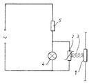
- 1 is a heat generator, for example a Radiant heater for the hob of an electric stove called.
- This Heat generator 1 is thermally coupled to a PTC element 2, which by the dashed multiple lines is shown.
- the PTC element 2 is parallel to a glow lamp 4, which is used as a warning device.
- glow lamps discharge lamps
- optical display elements such as Light emitting diodes (LED), mechanically under the influence of the applied voltage adjustable indicators or light bulbs can be used.
- LED Light emitting diodes
- the PTC element 2 now has a predetermined switching temperature. As long as that Temperature of the heat generator 1 below the switching temperature of the PTC element 2, the PTC element 2 is low-resistance. This is in this Switching state depending on the radiated heat from the heat generator 1 the warning element 4 is short-circuited and therefore cannot light up or do not emit an acoustic warning tone. If the temperature of the heat generator rises, which, for example, in the case of radiant heaters for cooking stoves, is very difficult high temperatures can be recognized by clearly visible glow, among such However, the PTC element can no longer be seen at high temperatures 2 via its thermal coupling the intended or predetermined Switching temperature. As a result, the PTC element 2 immediately becomes high-resistance.
- the optical Display 4 is no longer short-circuited and can in the event of a Glow lamp or a light emitting diode light up.
- This lighting up means for the operator or for people present at random and above all also for children, that the radiant heater or the hotplate is another one high temperature, which can lead to burns or when touched can lead to technical errors.
- the series resistor 5 connected to the optical warning element 4 is proportional high impedance, so that the current flowing through it the PTC element 2 cannot keep in the HOT state by self-heating.
- the Temperature limiter for radiant heating is also particularly easy to use only one contact can be formed. This allows its size to be space-saving being held.
Landscapes
- Engineering & Computer Science (AREA)
- Food Science & Technology (AREA)
- Chemical & Material Sciences (AREA)
- Combustion & Propulsion (AREA)
- Mechanical Engineering (AREA)
- General Engineering & Computer Science (AREA)
- Electric Stoves And Ranges (AREA)
- Control Of Resistance Heating (AREA)
Abstract
Description

Claims (3)
- Schaltungsanordnung zur Anzeige der Restwärme einer Wärmequelle nach Abschalten eines elektrischen Wärmeerzeugers (1), insbesondere der Restwärme einer Kochmulde (Strahlungsheizkörper) eines elektrischen Kochherdes, mit einem keramischen Kaltleiter (PTC-Element 2) und einem Warnelement (4),
dadurch gekennzeichnet,
daß der Kaltleiter (2) selbst als Schaltelement ausgebildet ist und das Warnelement (4) in Abhängigkeit von seiner Schalttemperatur steuert. - Schaltungsanordnung zur Anzeige der Restwärme einer Wärmequelle nach Anspruch 1,
dadurch gekennzeichnet,
daß das PTC-Element (2) mit entsprechend vorgegebener Schalttemperatur parallel zum Warnelement (4) liegt und das Warnelement unterhalb der Schalttemperatur kurzschließt. - Schaltungsanordnung zur Anzeige der Restwärme einer Wärmequelle nach Anspruch 1,
dadurch gekennzeichnet,
daß der Vorwiderstand (5) des Warnelementes (4) so hochohmig ist, daß der durch ihn fließende Strom das PTC-Element (2) nicht durch Eigenerwärmung in einem HEISS-Zustand hält.
Applications Claiming Priority (2)
| Application Number | Priority Date | Filing Date | Title |
|---|---|---|---|
| DE1999136072 DE19936072A1 (de) | 1999-07-30 | 1999-07-30 | Schaltungsanordnung zur Anzeige der Restwärme einer abgeschalteten Wärmequelle |
| DE19936072 | 1999-07-30 |
Publications (2)
| Publication Number | Publication Date |
|---|---|
| EP1072844A2 true EP1072844A2 (de) | 2001-01-31 |
| EP1072844A3 EP1072844A3 (de) | 2002-05-08 |
Family
ID=7916735
Family Applications (1)
| Application Number | Title | Priority Date | Filing Date |
|---|---|---|---|
| EP00113970A Withdrawn EP1072844A3 (de) | 1999-07-30 | 2000-07-01 | Schaltungsanordnung zur Anzeige der Restwärme einer abgeschalteten Wärmequelle |
Country Status (2)
| Country | Link |
|---|---|
| EP (1) | EP1072844A3 (de) |
| DE (1) | DE19936072A1 (de) |
Families Citing this family (1)
| Publication number | Priority date | Publication date | Assignee | Title |
|---|---|---|---|---|
| DE102006011901A1 (de) * | 2006-03-09 | 2007-09-13 | E.G.O. Elektro-Gerätebau GmbH | Restwärmeanzeige für ein Kochfeld sowie Verfahren zur Restwärmeanzeige für ein Kochfeld und Kochfeld |
Family Cites Families (3)
| Publication number | Priority date | Publication date | Assignee | Title |
|---|---|---|---|---|
| DE3138703A1 (de) * | 1981-09-29 | 1983-04-07 | Siemens Ag | Schaltungsanordnung zur anzeige des temperaturzustandes einer waemrequelle |
| DE3302740A1 (de) * | 1983-01-27 | 1984-08-02 | Siemens Ag | Schaltungsanordnung zur anzeige der restwaerme einer waermequelle nach abschalten des elektrischen waermeerzeugers |
| DE4439651C1 (de) * | 1994-11-07 | 1996-03-14 | Bosch Siemens Hausgeraete | Anzeigevorrichtung für ein elektrisches Haushaltsgerät |
-
1999
- 1999-07-30 DE DE1999136072 patent/DE19936072A1/de not_active Withdrawn
-
2000
- 2000-07-01 EP EP00113970A patent/EP1072844A3/de not_active Withdrawn
Also Published As
| Publication number | Publication date |
|---|---|
| EP1072844A3 (de) | 2002-05-08 |
| DE19936072A1 (de) | 2001-02-01 |
Similar Documents
| Publication | Publication Date | Title |
|---|---|---|
| DE2802625C3 (de) | Glühkerze | |
| CH654397A5 (de) | Elektrischer kochherd. | |
| DE202014010639U1 (de) | Ein Anzündaktivator für eine neue elektrisch beheizbare Zigarette | |
| DE2641274C3 (de) | Sicherheitseinrichtung für gasbeheizte, transparente Glaskeramikkochflächen | |
| DE3502525A1 (de) | Gluehelement | |
| DE2808181A1 (de) | Glaskeramik-kochfeld | |
| EP0927428B1 (de) | Strahlungsheizkörper für eine kochstelle | |
| DE1590287A1 (de) | Elektrisches Widerstandselement zum Einfuehren in eine Flamme | |
| DE3623130A1 (de) | Strahlungsbeheizung | |
| DE102007040891A1 (de) | Heizeinrichtung, Verfahren zum Betrieb einer Heizeinrichtung und Elektrowärmegerät mit einer solchen Heizeinrichtung | |
| EP1072844A2 (de) | Schaltungsanordnung zur Anzeige der Restwärme einer abgeschalteten Wärmequelle | |
| DE4417990B4 (de) | Flüssigkristallanzeige | |
| DE102016209147A1 (de) | Haushalts-Gargerät | |
| DE3840360A1 (de) | Strahlungs-heizkoerper | |
| DE60101783T2 (de) | Anzeigevorrichtung für Flüssigkeitsheizgeräte | |
| DE3104265A1 (de) | Elektroherd mit warn- und restwaermeanzeige der kochflaechen | |
| DE4224666C2 (de) | Schaltung eines Strahlungsheizkörpers | |
| DE3204119A1 (de) | Elektroherd mit temperaturwarneinrichtung | |
| DE102016209163A1 (de) | Haushalts-Gargerät | |
| DE1918662A1 (de) | Schaltgeraet | |
| DE102006011901A1 (de) | Restwärmeanzeige für ein Kochfeld sowie Verfahren zur Restwärmeanzeige für ein Kochfeld und Kochfeld | |
| DE3302740A1 (de) | Schaltungsanordnung zur anzeige der restwaerme einer waermequelle nach abschalten des elektrischen waermeerzeugers | |
| DE2605643C3 (de) | Anzeigevorrichtung für den Verkalkungsgrad von Wassererhitzern in elektrischen Haushaltsgeräten, insbesondere elektrischen Kaffeemaschinen | |
| DE1673502A1 (de) | Automatisch arbeitendes Geraet zur Erhitzung von Wasser | |
| AT219737B (de) | Schalteinrichtung für elektrische Wärmegeräte |
Legal Events
| Date | Code | Title | Description |
|---|---|---|---|
| PUAI | Public reference made under article 153(3) epc to a published international application that has entered the european phase |
Free format text: ORIGINAL CODE: 0009012 |
|
| AK | Designated contracting states |
Kind code of ref document: A2 Designated state(s): AT BE CH CY DE DK ES FI FR GB GR IE IT LI LU MC NL PT SE |
|
| AX | Request for extension of the european patent |
Free format text: AL;LT;LV;MK;RO;SI |
|
| PUAL | Search report despatched |
Free format text: ORIGINAL CODE: 0009013 |
|
| AK | Designated contracting states |
Kind code of ref document: A3 Designated state(s): AT BE CH CY DE DK ES FI FR GB GR IE IT LI LU MC NL PT SE |
|
| AX | Request for extension of the european patent |
Free format text: AL;LT;LV;MK;RO;SI |
|
| 17P | Request for examination filed |
Effective date: 20020523 |
|
| AKX | Designation fees paid |
Designated state(s): AT DE ES GB IT |
|
| 17Q | First examination report despatched |
Effective date: 20030901 |
|
| STAA | Information on the status of an ep patent application or granted ep patent |
Free format text: STATUS: THE APPLICATION IS DEEMED TO BE WITHDRAWN |
|
| 18D | Application deemed to be withdrawn |
Effective date: 20040312 |