EP1072784A2 - Steuerventil zur Abgasrückführung - Google Patents
Steuerventil zur Abgasrückführung Download PDFInfo
- Publication number
- EP1072784A2 EP1072784A2 EP00115420A EP00115420A EP1072784A2 EP 1072784 A2 EP1072784 A2 EP 1072784A2 EP 00115420 A EP00115420 A EP 00115420A EP 00115420 A EP00115420 A EP 00115420A EP 1072784 A2 EP1072784 A2 EP 1072784A2
- Authority
- EP
- European Patent Office
- Prior art keywords
- valve
- chamber
- valve body
- exhaust gas
- opening
- Prior art date
- Legal status (The legal status is an assumption and is not a legal conclusion. Google has not performed a legal analysis and makes no representation as to the accuracy of the status listed.)
- Granted
Links
Images
Classifications
-
- F—MECHANICAL ENGINEERING; LIGHTING; HEATING; WEAPONS; BLASTING
- F02—COMBUSTION ENGINES; HOT-GAS OR COMBUSTION-PRODUCT ENGINE PLANTS
- F02M—SUPPLYING COMBUSTION ENGINES IN GENERAL WITH COMBUSTIBLE MIXTURES OR CONSTITUENTS THEREOF
- F02M26/00—Engine-pertinent apparatus for adding exhaust gases to combustion-air, main fuel or fuel-air mixture, e.g. by exhaust gas recirculation [EGR] systems
- F02M26/65—Constructional details of EGR valves
- F02M26/66—Lift valves, e.g. poppet valves
- F02M26/68—Closing members; Valve seats; Flow passages
-
- F—MECHANICAL ENGINEERING; LIGHTING; HEATING; WEAPONS; BLASTING
- F02—COMBUSTION ENGINES; HOT-GAS OR COMBUSTION-PRODUCT ENGINE PLANTS
- F02M—SUPPLYING COMBUSTION ENGINES IN GENERAL WITH COMBUSTIBLE MIXTURES OR CONSTITUENTS THEREOF
- F02M26/00—Engine-pertinent apparatus for adding exhaust gases to combustion-air, main fuel or fuel-air mixture, e.g. by exhaust gas recirculation [EGR] systems
- F02M26/52—Systems for actuating EGR valves
- F02M26/53—Systems for actuating EGR valves using electric actuators, e.g. solenoids
-
- F—MECHANICAL ENGINEERING; LIGHTING; HEATING; WEAPONS; BLASTING
- F02—COMBUSTION ENGINES; HOT-GAS OR COMBUSTION-PRODUCT ENGINE PLANTS
- F02M—SUPPLYING COMBUSTION ENGINES IN GENERAL WITH COMBUSTIBLE MIXTURES OR CONSTITUENTS THEREOF
- F02M26/00—Engine-pertinent apparatus for adding exhaust gases to combustion-air, main fuel or fuel-air mixture, e.g. by exhaust gas recirculation [EGR] systems
- F02M26/65—Constructional details of EGR valves
- F02M26/66—Lift valves, e.g. poppet valves
- F02M26/67—Pintles; Spindles; Springs; Bearings; Sealings; Connections to actuators
Definitions
- the invention relates to a control valve for exhaust gas recirculation in an air intake or fuel processing system of an internal combustion engine.
- a valve housing in which one with an outlet of the internal combustion engine connectable exhaust gas inlet, a first chamber which can be connected to the air intake or fuel processing system and a second one in flow communication with the first chamber Chamber is formed, wherein the first chamber and the second chamber each have an opening opening into the exhaust gas inlet, with an Slidably mounted in the valve housing, extending through the openings Valve body, on which two valve elements for closing of the openings are provided, and with an actuator to and from forth moving the valve body between a release position and a Closed position for opening and closing at least one of the openings can be activated.
- a control valve of the type mentioned is for example from the DE 43 38 192 A1 or EP 0 900 931 A2 and is known in particular used in motor vehicles to part of the from the outlet of the Exhaust gas flowing out of the internal combustion engine of the fuel processing system to feed the internal combustion engine again.
- the peak combustion temperature is lowered, whereby the temperature-dependent nitrogen oxide emission is reduced or fuel consumption is reduced.
- the valve body has two valve elements which are in the exhaust gas inlet close the openings of the two chambers. Doing so achieved that the pressure acting in the exhaust gas inlet at the opposite Valve elements of the valve body in opposite Directional forces caused, at least partially mutually cancel.
- the first and second chambers serve the same purpose in fluid communication with each other, so that in the respective Chamber acting pressure opposed to the two valve elements acting forces are generated, which are at least mutually at least cancel.
- the two chambers are in the known control valves through a bypass that is adjacent to the exhaust gas inlet on the valve housing is formed, in fluid communication with each other.
- the invention solves the problem by a control valve with the features according to claim 1 and in particular in that at least in the valve body a pressure compensation channel is formed, the two chambers connects together in the valve housing.
- the two are in the valve housing formed chambers by the formed in the valve body Pressure equalization channel connected to each other, so that an additional Bypass or flow channel guided to the side of the exhaust gas inlet can be dispensed with. That when moved to the release position Valve body from the exhaust gas inlet into the first and / or second chamber Incoming exhaust gas can flow through the valve elements after the openings are closed in a simple manner by the in the valve body trained pressure equalization channel flow to the pressure between balance the two chambers. In this way it is achieved that the same pressure acts in both chambers, so that by the forces acting on the valve elements in the chambers, that act in the direction of movement of the valve body, each other at least partially or completely cancel.
- Valve elements can also be affected by atmospheric pressure caused compressive force that acts in the direction of movement of the valve body and, if necessary, attacks it, are taken into account.
- the first valve element is a valve disk that can be opened and closed serves the opening between the exhaust gas inlet and the first chamber.
- the second valve element is a part that is firmly connected to the valve body piston-shaped valve insert which defines the opening of the second chamber to the exhaust gas inlet both in the release position and in the The valve body is in the closed position.
- the exhaust gas in the exhaust gas inlet flows into the release position moved valve body only through the first opening into the first chamber, while the second valve element designed as a valve insert is the second Chamber still closed.
- the second valve element works on this embodiment as attached to the valve body, movable with it Pressure compensation element at which both the exhaust gas inlet and the pressure acting in the second chamber can also attack the on the first valve element through the one in the exhaust gas inlet and the first chamber to be able to compensate for the pressure caused. Also here the pressure equalization takes place between the first and second chamber through the pressure compensation channel in the valve body.
- the two valve elements the two openings of the chambers in the release position of the valve body free at the same time or close it at the same time if the Valve body is moved back into the closed position.
- valve body is designed as a deep-drawn part a first collar as the first valve element and second valve element a second fret is formed.
- valve body when the valve body is formed as a deep-drawn part, its weight compared to conventional valve bodies comparatively small, so that inertia-related influences, that occur when the valve body is moved back and forth Influence when setting the control valve than comparable conventional ones Control valves.
- valve body is between the first as Bund trained valve element and the second trained as a collar Valve element formed a hollow conical section, which is in the exhaust gas inlet is arranged.
- the second fret goes into a bell-shaped one Section over that with the inside diameter of the hollow cone Section is in flow connection and at least one opening is formed in connection with the second chamber.
- the hollow-conical design of the section achieved that the shaft formed by the hollow conical section Valve body has a higher rigidity than one made of a solid material manufactured valve stem, so that the risk of bending the valve stem and leakage caused thereby compared to a conventional one Valve body is small.
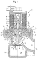
- Fig. 1 shows a sectional side view of a first embodiment a control valve 10, which in a motor vehicle, in particular in a Passenger cars, arranged in an exhaust gas recirculation line (not shown) is through which a partial volume flow of an outlet from an Internal combustion engine (not shown) flowing out of the motor vehicle Exhaust gas volume flow of an air intake or fuel processing system (Not shown) supplied to the internal combustion engine becomes.
- the control valve 10 has a valve housing 12, the a housing side 14 shown in Fig. 1 is machined flat. At the Housing side 14 is an electromagnetic actuator 16 by screws 18 and 20 attached, the structure of which will be explained later.
- an exhaust gas inlet 22 is formed, which by a Channel 24 in a first connecting flange 26 of the valve housing 12 flows.
- the first connecting flange 26 is in the installed state of the Control valve 10 with one at the outlet of the internal combustion engine connected pipeline connected.
- Adjacent to the exhaust gas inlet 22 is a first one in the valve housing 12 Chamber 28 formed, which is shown in Fig. 1 under the exhaust gas inlet 22 is.
- the first chamber 28 is through a first opening 30 with the Exhaust gas inlet 22 in connection and opens into one on the valve housing 12 trained second connecting flange 32, which in Fig. 1 on the left housing wall of the valve housing 12 is shown.
- the exhaust gas inlet 22 On its side opposite the first opening 30 is the exhaust gas inlet 22 open and goes to form a first paragraph 34 and one second paragraph 36 of larger diameter in the flat housing side 14 over.
- a rotationally symmetrical Insert 38 used in the open exhaust gas inlet 22 .
- the insert 38 has a sleeve-shaped Section 40, which projects into the exhaust gas inlet 22 and with its End face arranged at a concentric to the first opening 30
- Valve ring 42 is supported in a on the partition between the exhaust gas inlet 22 and the first chamber 28 formed, annular receptacle 44 is held.
- annular receptacle 44 In the sleeve-shaped section 40 there are approximately two rectangular recesses 46 formed at the level of the channel 24 are arranged.
- the sleeve-shaped section 40 goes into a plate-shaped Section 48 of insert 38 over which is perpendicular to the sleeve-shaped section 40 has a curved peripheral edge and with which the insert 38 rests on the second paragraph 36.
- a sealing ring 50 is inserted, the Exhaust gas inlet 22 closes at least approximately gas-tight to the outside.
- a guide insert 52 is inserted, on the Exhaust inlet 22 facing the bottom a concentric to the sleeve-shaped Section 40 arranged guide bush 54 is integrally formed.
- the Insert 38 and the guide insert 52 are by an electromagnetic Actuator 16 provided housing plate 56 in its in Fig. 1st shown installed position, being between the housing plate 56 and the top of the guide insert facing away from the guide bush 54 52 an annular spring 58 is clamped.
- a valve tappet 60 of a valve body projects through the guide bushing 54 62, whose one end shown in Fig. 1 in a longitudinal direction of the valve lifter 60 slidably mounted in the actuator 16 armature 64 of the actuator 16 is held.
- the armature 64 in turn by one facing the electromagnetic actuator 16 Top of the guide insert 52 supporting compression spring 66 in held in a rest position, in which the valve lifter 60 is in its closed position located, as will be explained later.
- the armature 64 is through an externally excitable magnetic winding 68, which when excited the armature 64 against the force of the compression spring 66 in an actuating position moves, in which the valve stem 60 moves to a release position will, as will be explained later.
- a valve disk 70 is attached at the other end of the valve lifter 60.
- the Circular valve disk 70 has a concentrically designed bushing 72 with which the valve plate 70 is pushed onto the valve lifter 60 and on this, for example, by riveting on the valve lifter 60 or by Shrink fit is attached.
- the inside of the valve plate 70 also has a chamfer 74, which in the Closed position of moving valve tappet 60 on the valve seat, in the direction of the first chamber 28 facing circumferential edge of the Valve ring 42 abuts and so the first opening 30 at least approximately encloses gastight.
- valve insert 76 On the end face of the socket 72 facing the insert 38 is a likewise on the valve lifter 60 pushed valve insert 76 on the in turn with a bushing section 78 on a radially outward projecting from the valve lifter 60 supporting collar 80 so that the Valve insert 76 between the bushing 72 and the support collar 80 mechanically is clamped.
- a ring portion 82 On the end face at base 80 of the sleeve portion 78 is a ring portion 82 is formed, with the the valve insert 76 is guided in the sleeve-shaped section 40.
- the Valve insert 76 forms with insert 38 and guide insert 52 a second chamber 84 in the valve housing 12.
- the second chamber 84 is by one formed in the valve lifter 60, in the longitudinal direction thereof running pressure equalization channel 86 (shown in dashed lines) with the first Chamber 28 connected, wherein at the end face of the valve lifter 60th near the valve plate 70 a first pressure equalization opening 88 and near the support collar 80 a second pressure equalization opening 90 the pressure equalization channel 86 connects to the first chamber 28 or second chamber 84.
- valve plate 70 of the valve body 62 closes the first opening 30, so that exhaust gas present in the exhaust gas inlet 22 from the outlet of the internal combustion engine cannot flow into the first chamber 28.
- valve insert 76 prevents exhaust gases from flowing into the second chamber 84 closed by the valve insert 76.
- the pressure acting in the exhaust gas inlet 22 on the side of the valve plate 70 pointing into the exhaust gas inlet 22 and the surface of the valve insert 76 also pointing into the exhaust gas inlet 22 in each case generates a pressure force F in1 or F in2 acting in the direction of movement of the valve tappet 60, whereby the force acting on the valve disk 70 pressing force F in1 acting on the valve insert 76 and the pressing force F in2 acting in the armature 64 at the end face of the valve plunger 60 atmospheric pressure force F acts in opposition at.
- the area on which the pressure acts on the valve disk 70 corresponds approximately to the area on which the pressure acting in the exhaust gas inlet 22 acts on the valve inlet 76 and the atmospheric pressure acting on the end face of the valve lifter 60, the forces F in1 and F in2 and F at each other so that the electromagnetic actuator 16 or the compression spring 66 are not subjected to any additional forces on the valve body 62.
- the pressure in the intake manifold of the air intake or fuel processing system also acts in the first chamber 28 and in the second chamber 84 connected to this by the pressure compensation channel 86, due to the pressure forces acting on the valve plate 70 and the valve insert 76 in the direction of movement of the valve body 62 F ex1 and F ex2 are generated, the compressive forces F ex1 and F ex2 arising here also canceling each other out.
- the magnet windings 68 of the actuator 16 are excited, whereby the armature 64 is moved against the force of the compression spring 66 into its position in which the valve tappet 60 of the valve body 62 attached to it is in a release position is moved.
- the valve plate 70 opens the first opening 30, so that exhaust gases flowing into the exhaust gas inlet 22 are fed through the first opening 30 into the first chamber 28 and out of this through the second connecting flange 32 and a pipeline to the intake manifold.
- the connection between the second chamber 84 and the exhaust gas inlet 22 remains interrupted by the valve insert 76.
- the second chamber 84 formed by the insert 38 and the guide insert 52. It is also conceivable, the second chamber 84 directly similar to the first chamber 28 in the valve housing 12, for example, by casting and to form the guide bush 54 in the valve housing 12. Further is it is also conceivable to replace the valve insert 76 with a second valve disk to use so that the second chamber 84 is in fluid communication can stand with the exhaust gas inlet 22. In this case the Pressure equalization channel 86 in the valve body 62 a correspondingly larger one Have diameter so that the desired mass flow between the second chamber 84 and the first chamber 28 can take place. As in the embodiment shown in Fig. 1, takes place in this modified Embodiment of pressure equalization between the chambers 28 and 84 also in this case through the then larger pressure equalization channel.
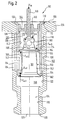
- Fig. 2 shows a second embodiment of a control valve 100, with which the exhaust gas recirculation between an outlet of an internal combustion engine (Not shown) and the intake manifold of the air intake or fuel processing system can be interrupted.
- the Control valve 100 has an approximately cylindrical valve housing 102, a stepped through bore 104 is formed in the longitudinal direction thereof that is on the two end faces 106 and 108 of the valve housing 102 is open.
- the stepped through hole 104 is close to that in FIG. 2 First end face 106 shown above a portion 110 of larger diameter on, which merges into the first end face 106 and a paragraph 112 forms.
- Paragraph 112 forms the transition to a second section 114 medium diameter, which is about two thirds of the Total length of the valve housing 102 extends and into a third section 116 smaller diameter passes with the through hole 104 ends at the second end face 108.
- the second section 114 are three annular recesses evenly distributed over its length 118, 120 and 122 formed, the third annular recess 122 the transition to the third section 116 of smaller diameter forms.
- valve housing 102 has a transverse to its longitudinal direction extending connecting bore 124 formed in the region of the second annular recess 120 opens into the through hole 104. On the connection bore 124 becomes one with the exhaust of the internal combustion engine connected pipeline connected.
- connection 128 is formed, to which one with related to the intake manifold of the internal combustion engine Return line can be connected.
- a hollow cylindrical insert 130 is inserted therein.
- the end of the insert 130 shown at the top in FIG. 2 is radial bent outwards and forms a peripheral edge 132 with which the insert 130 is supported on the shoulder 112 of the through hole 104.
- a bore 134 provided with the connection bore 124 of the valve housing 102 is aligned so that the insert 130 with its continuous Longitudinal bore 136 communicates with the connection bore 124.
- the longitudinal bore 136 is also stepped and points close its edge 132 on a shoulder 138, which in a bore section 140 smaller diameter passes.
- the bore section 140 is smaller Diameter ends immediately before the bore 134 and goes in a larger diameter bore section 142 extending up to extends to the end face of the insert 130.
- a guide insert 144 is inserted, which is attached supports the paragraph 138 and in the middle a guide bush 146 having.
- a valve tappet 148 is guided in the guide bushing 146 with one end out of the guide bush 146 towards the first Front 106 protrudes, which can be coupled to the actuator.
- valve lifter 148 At the other end of valve lifter 148, which extends into insert 130 a valve body 150 attached.
- the valve body 150 was manufactured by deep drawing and has one hollow conical section 152, at the free end of a radial outwardly projecting first sealing collar 154 is formed.
- the hollow cone-shaped section 152 forms a second sealing collar 156, which also protrudes radially outwards, into one hollow bell-shaped portion 158 with which the valve body 150 is attached to the valve lifter 148.
- a plurality of openings 160 are formed which are aligned with the interior of the hollow-conical section 152 are in flow connection, which is open at its end face shown in Fig. 2 below, which in a pressure equalization channel 161 is formed in the valve body 150.
- the first Sealing collar 154 of valve body 150 has a first chamfer 162, the inner circumferential edge formed on the end face of the insert 130 the longitudinal bore 136 abuts.
- the second sealing collar 156 has on its circumferential surface a second chamfer 164, which with the paragraph between the smaller diameter bore section 140 and is in contact with the larger diameter bore portion 142.
- the length of the larger diameter bore section 142 is so dimensioned that the two sealing collars 154 and 156 of the valve body 150 gas-tight against the insert 130 when the valve body 150 moved by the actuator into its closed position shown in FIG. 2 is.
- the bore section 142 delimits a larger diameter an exhaust gas inlet 166, which is in the closed position of the valve body 150 is closed by the two sealing collars 154 and 156.
- the third annular recess 122 and the third section smaller Diameter 116 of the through hole 104 form a first chamber 168, which, as already explained, with the intake manifold of the internal combustion engine communicates.
- the guide insert 144 forms with the bore section 140 of smaller diameter of the longitudinal bore 136 of the insert 130, a second chamber 170 through which second sealing collar 156 is closed when the valve body 150 is moved into its closed position, as shown in Fig. 2.
- pressure forces F in1 and F in1 act on the sealing collars 154 and 156 in this control valve 100 as a result of the pressure acting in the exhaust gas inlet 166, said pressure forces running in the opposite direction to one another in the direction of movement of the valve body 150. Since the effective area on the two sealing collars 154 and 156 is dimensioned such that the two compressive forces F in1 and F in2 are approximately of the same size, these equalize.
- the pressure acting in the first chamber 158 and the second chamber 170 generates on the sealing collars 154 and 156 and on the inside and outside of the bell-shaped section 152 and the atmospheric pressure acting on the end face of the valve lifter 148 in the direction of movement of the valve body 150 Compression forces F ex1 and F ex2 as well as F ex3 , F ex4 and F at .
- the effective areas on which the pressure acting in the first chamber 168 and the second chamber 170 and the atmospheric pressure acting on the end face of the valve lifter 60 act are dimensioned such that the in Compensate the direction of movement of the valve body 150 acting forces F ex1 and F ex2 as well as F ex3 , F ex4 and F at .
- the actuator for moving the valve body 150 between its closed position and its release position only gas forces in the valve body 150 which are low compared to the pressure force caused by the atmospheric pressure, frictional forces and spring forces by which the valve body 150 is held in its closed position will have to overcome.
- control valve 100 as well pressure of the first chamber 168 and the second chamber 170 through the one of the openings 160 and the hollow cone-shaped section 152 formed pressure equalization channel 161 compensated so that on one additional flow channel or bypass between the two chambers 168 and 170 can be dispensed with.
- the actuator holds the valve body 150 in the closed position shown in Fig. 2, in which the exhaust gas inlet 166 at least approximately gastight from the two chambers 168 and 170 is separated.
- the valve body 150 in its longitudinal direction from the closed position to its release position moves in the sealing collars 154 and 156 from their contact surfaces are moved away on the insert 130 so that between the valve body 150 and the inner wall of the longitudinal bore 136 annular openings through which the exhaust gas from the exhaust gas inlet 166 can flow into the first chamber 168 and the second chamber 170.
- the opening 160 in the bell-shaped section 158 of the Valve body 150 a pressure equalization and a mass flow from the first Chamber 168 through the pressure equalization channel 161 to the second Chamber 170 allows.
- the exhaust gas flows through the first chamber 168 then in the intake manifold of the internal combustion engine.
- valve body 150 moved back to its closed position with the help of the actuator, in which the sealing collars 154 and 156 the flow connection between interrupt the exhaust gas inlet 166 and the two chambers 168 and 170.
- the pressure equalization takes place between the first and second Chamber 168 and 170 in turn through openings 160 and Pressure equalization channel 161.
- valve body 150 it is also possible to use the valve body 150 so that the second chamber 170 also in the release position is separated from the exhaust gas inlet 166 so that no exhaust gas in can flow directly into the second chamber 170.
- the pressure equalization this modification also takes place between the two chambers 168 and 170 of the second embodiment through the pressure equalization channel 161 serving hollow valve body 150 and the openings 160.
- the hollow valve body 150 need not necessarily be deep drawn. He can also consist of several individual components, for example made by turning be formed, for example by welding together are connected.
Landscapes
- Engineering & Computer Science (AREA)
- Chemical & Material Sciences (AREA)
- Combustion & Propulsion (AREA)
- Mechanical Engineering (AREA)
- General Engineering & Computer Science (AREA)
- Fluid-Driven Valves (AREA)
- Valve Device For Special Equipments (AREA)
- Exhaust-Gas Circulating Devices (AREA)
Abstract
Description
- Fig. 1
- eine geschnittene Seitenansicht eines ersten Ausführungsbeispieles eines erfindungsgemäßen Steuerventils, bei dem nur eine von zwei Kammern mit einem Abgaseinlaß verbindbar ist, und
- Fig. 2
- eine geschnittene Seitenansicht eines zweiten Ausführungsbeispiels eines erfindungsgemäßen Steuerventils mit einem tiefgezogenen Ventilkörper.
- 10
- Steuerventil
- 12
- Ventilgehäuse
- 14
- Gehäuseseite
- 16
- elektromagnetischer Aktuator
- 18
- Schraube
- 20
- Schraube
- 22
- Abgaseinlaß
- 24
- Kanal
- 26
- erster Anschlußflansch
- 28
- erste Kammer
- 30
- erste Öffnung
- 32
- zweiter Anschlußflansch
- 34
- erster Absatz
- 36
- zweiter Absatz
- 38
- Einsatz
- 40
- hülsenförmiger Abschnitt
- 42
- Ventilring
- 44
- Aufnahme
- 46
- Aussparung
- 48
- tellerförmiger Abschnitt
- 50
- Dichtungsring
- 52
- Führungseinsatz
- 54
- Führungsbuchse
- 56
- Gehäuseplatte
- 58
- Feder
- 60
- Ventilstößel
- 62
- Ventilkörper
- 64
- Anker
- 66
- Druckfeder
- 68
- Magnetwicklung
- 70
- Ventilteller
- 72
- Buchse
- 74
- Fase
- 76
- Ventileinsatz
- 78
- Buchsenabschnitt
- 80
- Stützbund
- 82
- Ringabschnitt
- 84
- zweite Kammer
- 86
- Druckausgleichskanal
- 88
- erste Druckausgleichsöffnung
- 90
- zweite Druckausgleichsöffnung
- Fin1
- am Ventilteller angreifende Druckkraft
- Fin2
- am Ventileinsatz angreifende Druckkraft
- Fex1
- am Ventilteller angreifende Druckkraft
- Fex2
- am Ventileinsatz angreifende Druckkraft
- Fat
- am Ventilstößel angreifende atmosphärische Druckkraft
- 100
- Steuerventil
- 102
- Ventilgehäuse
- 104
- Durchgangsbohrung
- 106
- erste Stirnseite
- 108
- zweite Stirnseite
- 110
- erster Abschnitt größeren Durchmessers
- 112
- Absatz
- 114
- zweiter Abschnitt mittleren Durchmessers
- 116
- dritter Abschnitt kleineren Durchmessers
- 118
- erste ringförmige Aussparung
- 120
- zweite ringförmige Aussparung
- 122
- dritte ringförmige Aussparung
- 124
- Anschlußbohrung
- 126
- Bund
- 128
- Anschluß
- 130
- Einsatz
- 132
- Rand
- 134
- Bohrung
- 136
- Längsbohrung
- 138
- Absatz
- 140
- Bohrungsabschnitt kleineren Durchmessers
- 142
- Bohrungsabschnitt größeren Durchmessers
- 144
- Führungseinsatz
- 146
- Führungsbuchse
- 148
- Ventilstößel
- 150
- Ventilkörper
- 152
- hohlkegelförmiger Abschnitt
- 154
- erster Dichtungsbund
- 156
- zweiter Dichtungsbund
- 158
- glockenförmiger Abschnitt
- 160
- Öffnungen
- 161
- Druckausgleichskanal
- 162
- erste Fase
- 164
- zweite Fase
- 166
- Abgaseinlaß
- 168
- erste Kammer
- 170
- zweite Kammer
- Fin1
- am ersten Dichtungsbund angreifende Druckkraft
- Fin2
- am Ventileinsatz angreifende Druckkraft
- Fex1
- am ersten Dichtungsbund angreifende erste Druckkraft
- Fex2
- am ersten Dichtungsbund angreifende zweite Druckkraft
- Fex3
- am zweiten Dichtungsbund angreifende erste Druckkraft
- Fex4
- am zweiten Dichtungsbund angreifende zweite Druckkraft
- Fat
- am Ventilstößel angreifende atmosphärische Druckkraft
Claims (11)
- Steuerventil zur Abgasrückführung in eine Luftansaug- bzw. Kraftstoffaufbereitungsanlage einer Verbrennungskraftmaschine,mit einem Ventilgehäuse(12; 102), in dem ein mit einem Auslaß der Verbrennungskraftmaschine verbindbarer Abgaseinlaß (22; 166), eine mit der Kraftstoffaufbereitungsanlage verbindbare erste Kammer (28; 168) und eine mit der ersten Kammer (28; 168) in Strömungsverbindung stehende zweite Kammer (84; 170) ausgebildet ist, wobei die erste Kammer (28; 168) und die zweite Kammer (84; 170) jeweils eine in den Abgaseinlaß (22; 166) mündende Öffnung (30; 136, 142) aufweisen,mit einem im Ventilgehäuse (12; 102) verschieblich gelagerten, sich durch die Öffnungen (30; 136, 142) erstreckenden Ventilkörper (62; 150), an dem zwei Ventilelemente (70, 76; 154, 156) zum Verschließen der Öffnungen (30; 136, 142) vorgesehen sind, undmit einem Aktuator (16), der zum hin und her Bewegen des Ventilkörpers (62; 150) zwischen einer Freigabestellung und einer Schließstellung zum Öffnen und Schließen mindestens einer der Öffnung (30; 136, 142) aktivierbar ist,
dadurch gekennzeichnet,daß im Ventilkörper (62; 150) mindestens ein Druckausgleichskanal (86, 161) ausgebildet ist, der die beiden Kammern (28, 84; 168, 170) im Ventilgehäuse (12; 102) miteinander verbindet. - Steuerventil nach Anspruch 1,
dadurch gekennzeichnet,daß die in die beiden Kammern (28, 84; 168, 170) zeigenden Seiten der beiden Ventilelemente (70, 76; 154, 156) derart gestaltet sind,daß die von dem in den Kammern (28, 84; 168, 170) wirkenden Druck an den Ventilelementen (70, 76; 154, 156) verursachten Druckkräfte (Fex1, Fex2, Fex3, Fex4), die in Bewegungsrichtung des Ventilkörpers (62; 150) wirken, zumindest annähernd gleich groß sind. - Steuerventil nach Anspruch 2,
dadurch gekennzeichnet,daß am Ventilkörper (62; 150) eine durch den atmosphärischen Druck verursachte Druckkraft (Fat) angreift, die in Bewegungsrichtun des Ventilkörpers (62; 150) wirkt und bei der Gestaltung der in die beiden Kammern (28, 84; 168, 170) zeigenden Seiten der beiden Ventilelemente (70, 76; 154, 156) mit berücksichtigt ist. - Steuerventil nach Anspruch 1,
dadurch gekennzeichnet,daß die in den Abgaseinlaß (22; 166) zeigenden Seiten der beiden Ventilelemente (70, 76; 154, 156) derart gestaltet sind, daß die von dem in dem Abgaseinlaß (22, 166) wirkenden Druck an den Ventilelementen (70, 76; 154, 156) verursachten Druckkräfte (Fin1 Fin2), die in Bewegungsrichtung des Ventilkörpers (62; 150) wirken, zumindest annähernd gleich groß sind. - Steuerventil nach Anspruch 1,
dadurch gekennzeichnet,daß das erste Ventilelement ein Ventilteller (70) zum Öffnen und Verschließen der Öffnung (30) zwischen dem Abgaseinlaß (22) und der ersten Kammer (28) ist, und daß das zweite Ventilelement ein mit dem Ventilkörper (62) fest verbundener Ventileinsatz (76) ist, der die Öffnung der zweiten Kammer (84) sowohl in der Freigabestellung als auch in der Schließstellung des Ventilkörpers (62) verschließt, wobei der Ventileinsatz (76) vorzugsweise in einer in den Abgaseinlaß (22) ragenden Hülse (40) verschieblich aufgenommen ist, in die die Öffnung der zweiten Kammer (84) zum Abgaseinlaß (22) mündet. - Steuerventil nach Anspruch 5,
dadurch gekennzeichnet,daß an dem Ventilteller (70) eine Buchse (72) vorgesehen ist, die auf einen Ventilstößel (60) des Ventilkörpers (62) aufgeschoben und an diesem befestigt ist, und daß der gleichfalls auf den Ventilstößel (60) aufgeschobene Ventileinsatz (76) zwischen einem vom Ventilstößel (60) radial nach außen abstehenden Stützbund (80) und einer Stirnseite der Buchse (72) eingespannt ist. - Steuerventil nach Anspruch 6,
dadurch gekennzeichnet,daß im Ventilstößel (60) der in Längsrichtung des Ventilstößels (60) verlaufende Druckausgleichskanal (86) ausgebildet ist, der an der in die erste Kammer (28) ragenden Stirnseite eine erste Druckausgleichsöffnung (88) und an dem durch die zweite Kammer (84) ragenden Abschnitt mindestens eine zweite Druckausgleichsöffnung (90) aufweist. - Steuerventil nach Anspruch 1,
dadurch gekennzeichnet,daß die beiden Ventilelemente die beiden Öffnung der Kammern 136; 142) in der Freigabestellung des Ventilkörpers (150) gleichzeitig freigeben und in der Schließstellung gleichzeitig zumindest annähernd gasdicht verschließen. - Steuerventil nach Anspruch 8,
dadurch gekennzeichnet,daß das erste Ventilelement und/oder das zweite Ventilelement ein vom Ventilkörper radial nach außen abstehender Bund (154, 156) ist, der an seiner Außenkante vorzugsweise eine abgeschrägte Ventilfläche (162, 164) aufweist, und daß an der Öffnung (136; 142) der ersten und/oder zweiten Kammer (168, 170) ein Ventilsitz ausgebildet ist, der zum gasdichten Verschließen der jeweiligen Öffnung (136, 142) mit dem Bund (154, 156) in Berührung kommt. - Steuerventil nach Anspruch 8,
dadurch gekennzeichnet,daß der Ventilkörper (150) ein Tiefziehteil ist, an dem als erstes Ventilelement ein erster Bund (154) und als zweites Ventilelement ein zweiter Bund (156) ausgeformt ist. - Steuerventil nach Anspruch 10,
dadurch gekennzeichnet,daß der Ventilkörper zwischen dem ersten und dem zweiten Bund (154, 156) einen hohlkegelförmigen ersten Abschnitt (152) aufweist, der zumindest teilweise im Abgaseinlaß (166) angeordnet ist, unddaß der zweite Bund (156) in einen glockenförmigen Abschnitt (158) übergeht, der mit dem ersten Abschnitt (152) in Strömungsverbindung steht und an dem mindestens eine mit der zweiten Kammer (170) in Verbindung stehende Öffnung (160) ausgebildet ist.
Applications Claiming Priority (2)
| Application Number | Priority Date | Filing Date | Title |
|---|---|---|---|
| DE19935483A DE19935483A1 (de) | 1999-07-28 | 1999-07-28 | Steuerventil zur Abgasrückführung |
| DE19935483 | 1999-07-28 |
Publications (3)
| Publication Number | Publication Date |
|---|---|
| EP1072784A2 true EP1072784A2 (de) | 2001-01-31 |
| EP1072784A3 EP1072784A3 (de) | 2001-10-10 |
| EP1072784B1 EP1072784B1 (de) | 2003-04-09 |
Family
ID=7916381
Family Applications (1)
| Application Number | Title | Priority Date | Filing Date |
|---|---|---|---|
| EP00115420A Expired - Lifetime EP1072784B1 (de) | 1999-07-28 | 2000-07-17 | Steuerventil zur Abgasrückführung |
Country Status (2)
| Country | Link |
|---|---|
| EP (1) | EP1072784B1 (de) |
| DE (2) | DE19935483A1 (de) |
Cited By (6)
| Publication number | Priority date | Publication date | Assignee | Title |
|---|---|---|---|---|
| EP1128054A3 (de) * | 2000-02-24 | 2002-08-28 | Delphi Technologies, Inc. | Dosierventilbaugruppe mit Druckausgleichvorrichtung für ein modulares Abgasrückführungsventil |
| EP1598543A1 (de) * | 2004-05-18 | 2005-11-23 | Pierburg GmbH | Regelbare Zwei-Wege-Ventilvorrichtung |
| WO2007048605A1 (de) * | 2005-10-29 | 2007-05-03 | Pierburg Gmbh | Schubumluftventilvorrichtung für eine brennkfraftmaschine |
| WO2011128191A1 (de) * | 2010-04-13 | 2011-10-20 | Pierbrug Gmbh | Anordnung eines ventils in einer bohrung eines kanalgehäuses |
| US8387383B2 (en) | 2005-10-29 | 2013-03-05 | Pierburg Gmbh | Ambient-air pulsed valve for internal combustion engines equipped with a turbocharger |
| WO2015055568A1 (de) * | 2013-10-14 | 2015-04-23 | Continental Automotive Gmbh | Ventil |
Citations (4)
| Publication number | Priority date | Publication date | Assignee | Title |
|---|---|---|---|---|
| DE3828998A1 (de) * | 1988-08-26 | 1990-03-08 | Zikesch Gmbh C H | Regelventil |
| EP0740064A1 (de) * | 1995-04-25 | 1996-10-30 | Pierburg Aktiengesellschaft | Abgasrückführsteuerventil |
| EP0900931A2 (de) * | 1997-09-04 | 1999-03-10 | General Motors Corporation | Abgasrückführungsventil |
| EP0928892A1 (de) * | 1998-01-12 | 1999-07-14 | Ranco Incorporated of Delaware | Druckkompensiertes Abgasrückführventil |
Family Cites Families (3)
| Publication number | Priority date | Publication date | Assignee | Title |
|---|---|---|---|---|
| DE2216562A1 (de) * | 1972-04-06 | 1973-11-08 | British Leyland Austin Morris | Brennkraftmaschine mit abgasrueckfuehrung |
| DE4039351A1 (de) * | 1990-12-10 | 1992-06-11 | Pierburg Gmbh | Elektromagnetisches steuerventil fuer abgasrueckfuehrung |
| JPH10274105A (ja) * | 1997-03-28 | 1998-10-13 | Nippon Soken Inc | Egr制御弁およびそれを用いた排気ガス再循環装置 |
-
1999
- 1999-07-28 DE DE19935483A patent/DE19935483A1/de not_active Withdrawn
-
2000
- 2000-07-17 EP EP00115420A patent/EP1072784B1/de not_active Expired - Lifetime
- 2000-07-17 DE DE50001684T patent/DE50001684D1/de not_active Expired - Fee Related
Patent Citations (4)
| Publication number | Priority date | Publication date | Assignee | Title |
|---|---|---|---|---|
| DE3828998A1 (de) * | 1988-08-26 | 1990-03-08 | Zikesch Gmbh C H | Regelventil |
| EP0740064A1 (de) * | 1995-04-25 | 1996-10-30 | Pierburg Aktiengesellschaft | Abgasrückführsteuerventil |
| EP0900931A2 (de) * | 1997-09-04 | 1999-03-10 | General Motors Corporation | Abgasrückführungsventil |
| EP0928892A1 (de) * | 1998-01-12 | 1999-07-14 | Ranco Incorporated of Delaware | Druckkompensiertes Abgasrückführventil |
Non-Patent Citations (1)
| Title |
|---|
| PATENT ABSTRACTS OF JAPAN vol. 1999, no. 01, 29. Januar 1999 (1999-01-29) & JP 10 274105 A (NIPPON SOKEN INC;DENSO CORP), 13. Oktober 1998 (1998-10-13) * |
Cited By (9)
| Publication number | Priority date | Publication date | Assignee | Title |
|---|---|---|---|---|
| EP1128054A3 (de) * | 2000-02-24 | 2002-08-28 | Delphi Technologies, Inc. | Dosierventilbaugruppe mit Druckausgleichvorrichtung für ein modulares Abgasrückführungsventil |
| EP1598543A1 (de) * | 2004-05-18 | 2005-11-23 | Pierburg GmbH | Regelbare Zwei-Wege-Ventilvorrichtung |
| WO2007048605A1 (de) * | 2005-10-29 | 2007-05-03 | Pierburg Gmbh | Schubumluftventilvorrichtung für eine brennkfraftmaschine |
| US8387383B2 (en) | 2005-10-29 | 2013-03-05 | Pierburg Gmbh | Ambient-air pulsed valve for internal combustion engines equipped with a turbocharger |
| WO2011128191A1 (de) * | 2010-04-13 | 2011-10-20 | Pierbrug Gmbh | Anordnung eines ventils in einer bohrung eines kanalgehäuses |
| JP2013524096A (ja) * | 2010-04-13 | 2013-06-17 | ピールブルク ゲゼルシャフト ミット ベシュレンクテル ハフツング | 通路ハウジングに設けられた孔内に配置された弁 |
| EP2558751B1 (de) | 2010-04-13 | 2015-10-07 | Pierburg GmbH | Anordnung eines ventils in einer bohrung eines kanalgehäuses |
| WO2015055568A1 (de) * | 2013-10-14 | 2015-04-23 | Continental Automotive Gmbh | Ventil |
| CN105658931A (zh) * | 2013-10-14 | 2016-06-08 | 大陆汽车有限责任公司 | 阀 |
Also Published As
| Publication number | Publication date |
|---|---|
| EP1072784B1 (de) | 2003-04-09 |
| EP1072784A3 (de) | 2001-10-10 |
| DE50001684D1 (de) | 2003-05-15 |
| DE19935483A1 (de) | 2001-02-01 |
Similar Documents
| Publication | Publication Date | Title |
|---|---|---|
| DE102005042679B4 (de) | Bypassventil für Verbrennungskraftmaschinen | |
| EP1579137B1 (de) | Ventil zum steuern eines fluids | |
| EP1431567B1 (de) | Brennstoffeinspritzventil für Verbrennungskraftmaschinen | |
| EP2291717B1 (de) | Druckregelventil | |
| DE4231239A1 (de) | Vorrichtung zur Regelung der Leerlaufdrehzahl einer Brennkraftmaschine | |
| WO2004044467A1 (de) | Elektromagnetisches hydraulikventil, insbesondere 3/2-wegeschaltventil zur steuerung eines variablen ventiltriebes einer brennkraftmaschine | |
| DE202018104140U1 (de) | Regelvorrichtung für einen Abgasturbolader | |
| EP1700058B1 (de) | Ventil zum steuern eines fluids | |
| DE102020206644A1 (de) | Elektromagnetventil, insbesondere für schlupfgeregelte Kraftfahrzeugbremsanlagen | |
| WO2009053219A1 (de) | Brennstoffeinspritzventil | |
| EP3280904B1 (de) | Gasventil | |
| DE102015206206A1 (de) | Gasventil | |
| DE102008005523A1 (de) | Kraftstoffinjektor | |
| EP1072784B1 (de) | Steuerventil zur Abgasrückführung | |
| DE19604889A1 (de) | Druckbegrenzungsventil | |
| DE102009027841A1 (de) | Kraftstoffeinspritzventil | |
| WO2011076471A1 (de) | Magnetventil sowie fahrerassistenzeinrichtung mit einem derartigen magnetventil | |
| WO2022028965A1 (de) | Ventil für fliessfähige medien | |
| DE60201800T2 (de) | Lagermodul für Abgasrückführsteuerventil | |
| DE102004010183A1 (de) | Einspritzventil | |
| WO2020020836A1 (de) | Ventil | |
| DE102017207845A1 (de) | Ventil zum Zumessen eines Fluids | |
| DE102017000316B3 (de) | Abblaseventil | |
| DE102018201148B4 (de) | Schaltventil für ein Aggregatelager eines Kraftfahrzeugs sowie entsprechendes Aggregatelager | |
| WO2020244875A1 (de) | Ventileinrichtung |
Legal Events
| Date | Code | Title | Description |
|---|---|---|---|
| PUAI | Public reference made under article 153(3) epc to a published international application that has entered the european phase |
Free format text: ORIGINAL CODE: 0009012 |
|
| AK | Designated contracting states |
Kind code of ref document: A2 Designated state(s): AT BE CH CY DE DK ES FI FR GB GR IE IT LI LU MC NL PT SE Kind code of ref document: A2 Designated state(s): DE FR GB IT |
|
| AX | Request for extension of the european patent |
Free format text: AL;LT;LV;MK;RO;SI |
|
| PUAL | Search report despatched |
Free format text: ORIGINAL CODE: 0009013 |
|
| AK | Designated contracting states |
Kind code of ref document: A3 Designated state(s): AT BE CH CY DE DK ES FI FR GB GR IE IT LI LU MC NL PT SE |
|
| AX | Request for extension of the european patent |
Free format text: AL;LT;LV;MK;RO;SI |
|
| 17P | Request for examination filed |
Effective date: 20011207 |
|
| 17Q | First examination report despatched |
Effective date: 20020405 |
|
| AKX | Designation fees paid |
Free format text: DE FR GB IT |
|
| GRAH | Despatch of communication of intention to grant a patent |
Free format text: ORIGINAL CODE: EPIDOS IGRA |
|
| GRAH | Despatch of communication of intention to grant a patent |
Free format text: ORIGINAL CODE: EPIDOS IGRA |
|
| GRAA | (expected) grant |
Free format text: ORIGINAL CODE: 0009210 |
|
| AK | Designated contracting states |
Designated state(s): DE FR GB IT |
|
| REG | Reference to a national code |
Ref country code: GB Ref legal event code: FG4D Free format text: NOT ENGLISH |
|
| GBT | Gb: translation of ep patent filed (gb section 77(6)(a)/1977) |
Effective date: 20030409 |
|
| ET | Fr: translation filed | ||
| PLBE | No opposition filed within time limit |
Free format text: ORIGINAL CODE: 0009261 |
|
| STAA | Information on the status of an ep patent application or granted ep patent |
Free format text: STATUS: NO OPPOSITION FILED WITHIN TIME LIMIT |
|
| 26N | No opposition filed |
Effective date: 20040112 |
|
| PG25 | Lapsed in a contracting state [announced via postgrant information from national office to epo] |
Ref country code: GB Free format text: LAPSE BECAUSE OF NON-PAYMENT OF DUE FEES Effective date: 20040717 |
|
| GBPC | Gb: european patent ceased through non-payment of renewal fee |
Effective date: 20040717 |
|
| PG25 | Lapsed in a contracting state [announced via postgrant information from national office to epo] |
Ref country code: IT Free format text: LAPSE BECAUSE OF NON-PAYMENT OF DUE FEES Effective date: 20050717 |
|
| PGFP | Annual fee paid to national office [announced via postgrant information from national office to epo] |
Ref country code: FR Payment date: 20090710 Year of fee payment: 10 |
|
| PGFP | Annual fee paid to national office [announced via postgrant information from national office to epo] |
Ref country code: DE Payment date: 20090709 Year of fee payment: 10 |
|
| REG | Reference to a national code |
Ref country code: FR Ref legal event code: ST Effective date: 20110331 |
|
| PG25 | Lapsed in a contracting state [announced via postgrant information from national office to epo] |
Ref country code: DE Free format text: LAPSE BECAUSE OF NON-PAYMENT OF DUE FEES Effective date: 20110201 |
|
| REG | Reference to a national code |
Ref country code: DE Ref legal event code: R119 Ref document number: 50001684 Country of ref document: DE Effective date: 20110201 |
|
| PG25 | Lapsed in a contracting state [announced via postgrant information from national office to epo] |
Ref country code: FR Free format text: LAPSE BECAUSE OF NON-PAYMENT OF DUE FEES Effective date: 20100802 |