EP1071108A2 - Elektromagnetischer Aktor, insbesondere elektromagnetischer Auslöser, insbesondere für einen Leitungsschutzschalter - Google Patents
Elektromagnetischer Aktor, insbesondere elektromagnetischer Auslöser, insbesondere für einen Leitungsschutzschalter Download PDFInfo
- Publication number
- EP1071108A2 EP1071108A2 EP00114808A EP00114808A EP1071108A2 EP 1071108 A2 EP1071108 A2 EP 1071108A2 EP 00114808 A EP00114808 A EP 00114808A EP 00114808 A EP00114808 A EP 00114808A EP 1071108 A2 EP1071108 A2 EP 1071108A2
- Authority
- EP
- European Patent Office
- Prior art keywords
- spring
- arm
- armature
- rocker
- actuator
- Prior art date
- Legal status (The legal status is an assumption and is not a legal conclusion. Google has not performed a legal analysis and makes no representation as to the accuracy of the status listed.)
- Granted
Links
Images
Classifications
-
- H—ELECTRICITY
- H01—ELECTRIC ELEMENTS
- H01H—ELECTRIC SWITCHES; RELAYS; SELECTORS; EMERGENCY PROTECTIVE DEVICES
- H01H71/00—Details of the protective switches or relays covered by groups H01H73/00 - H01H83/00
- H01H71/10—Operating or release mechanisms
- H01H71/12—Automatic release mechanisms with or without manual release
- H01H71/24—Electromagnetic mechanisms
- H01H71/2463—Electromagnetic mechanisms with plunger type armatures
Definitions
- the invention relates to an electromagnetic actuator according to the preamble of the claim 1.
- Such actuators are used on a large scale, especially in circuit breakers, used to detect a short circuit and switch it off.
- the actuator or Triggers have a yoke and inside the yoke a coil that has an armature and surrounds a nucleus. If a short circuit occurs, the anchor will be against the core pulled and the movement of the armature on a contact lever or on movable Transfer contact piece and / or to a key switch; when the movement of the Switch lock is only transferred to the contact piece, the contact piece return to the on position after the short circuit has ended; about the Switch lock, the movable contact piece is opened permanently.
- a captive magnet is used to set the tripping point or the tripping current used; for magnetic releases there are also arrangements with an external one Cuff spring.
- the magnetic triggers which serve as short interrupters, normally have a magnet for captivation.
- the disadvantage here is the high cost of the magnet; the holding force of the magnet is limited by its geometry, and the response value is polarity dependent. Furthermore, the force curve cannot be changed, since practically no force acts on the anchor after the magnet has been torn off.
- the object of the invention is to provide an actuator of the type mentioned at which the release is independent of the pole and the force course of the bondage for different Variants can be adjusted.
- rocker in her knee is rotatably mounted.
- the axis of rotation of the rocker is located radially next to the anchor.
- the seesaw is approximately L-shaped, with its arm coupled to the anchor approximately vertical approximately parallel to the central axis of the armature and its arm coupled with the spring to get lost.
- the anchor jumps so that the dead center position can be reached or exceeded against the direction of force of the spring.
- Another advantageous embodiment of the invention may consist in that the The rocker is mounted on the yoke, in the same way the spring can with its other Be attached to the yoke at the end.
- the actuator which is then used as a trigger z. B. used in a breaker is reset by a contact pressure spring that is operated directly by the trigger Contact lever is assigned to sufficient when switched on To generate contact pressure.
- the actuator is used as a trigger in a circuit breaker used, then it is by means of the switch toggle over the switch lock of the contact lever deferred.
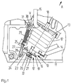
- the actuator according to the invention which has the reference number 10 in FIG. 1, is in one Housing 11 of a circuit breaker housed.
- the actuator 10 has a Yoke 12, one of which has a yoke web running parallel to the longitudinal direction of the actuator 10 shows up under supervision.
- Inside the yoke there is a coil 13 with a coil feed line 14 and a coil lead 15.
- the coil 13 surrounds a plunger 16, the ends 17 and 18 of which axially project beyond the actuator or trigger 10.
- the armature has a guide plate 19 extending transversely to the longitudinal axis and an in Distance to this holding plate 20, through which an intermediate space 21 is formed, into which a first arm 22 of a rocker 23 engages, so that the first arm 22 with the anchor 16 is positively coupled.
- the rocker 23 has a second one running approximately perpendicular to the first arm 22 Arm 24; it is on a projection 25 of the yoke 12 in a receptacle 26 with it Rotation axis 27 rotatably mounted.
- At the free end of the second Armes 24 is hooked one end 28 of a tension spring 29, the other end 31 of a projection 30 is also attached to the yoke.
- the connecting line V between the attachment point 30, 31 and the axis of rotation 27 is a dead center line.
- the spring 29 acts there is the dead center line V here on the left, a force on the one hand on the second arm 24, which the rocker 23 tries to turn clockwise, and on the other hand over the arm 22 a force on the armature 16, whereby the armature in the ready to trip shown in Fig. 1 Position is held.
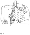
- the spring acts on the rocker a torque that runs counterclockwise, so that the switch-off movement of the armature is additionally accelerated by the force of the spring.
Landscapes
- Physics & Mathematics (AREA)
- Electromagnetism (AREA)
- Breakers (AREA)
- Valve Device For Special Equipments (AREA)
- Switches That Are Operated By Magnetic Or Electric Fields (AREA)
- Electronic Switches (AREA)
- Iron Core Of Rotating Electric Machines (AREA)
- Magnetically Actuated Valves (AREA)
- Driving Mechanisms And Operating Circuits Of Arc-Extinguishing High-Tension Switches (AREA)
Abstract
Description
- Fig. 1
- den Aktor in auslösebereiter Stellung, und
- Fig. 2
- den Aktor in ausgelöster Stellung.
Claims (10)
- Elektomagnetischer Aktor, insbesondere elektromagnetischer Auslöser für einen Leitungsschutzschalter oder dgl, mit einem Joch, einer Spule, einem Anker, einem Kern und einer Fesselfeder, dadurch gekennzeichnet, daß eine bezogen auf den Aktor ortsfest drehbar gelagerte Wippe (23) vorgesehen ist, deren erster Arm (22) mit dem Anker (16) gekoppelt ist und an derem zweiten Arm (24) ein Ende einer Fesselfeder (29) angreift, deren anderes Ende ebenfalls ortsfest festgelegt ist, und daß die Wippe (23) so angeordnet ist, daß der Anlenkpunkt (28) der Feder (29) am zweiten Arm auf eine durch den Drehpunkt und den Anlenkpunkt verlaufende Totpunktlinie (V) beim Auslösevorgang hinschwenkt, so daß die Kraft der den Anker (16) in dessen Ruhestellung festhaltenden Feder sich beim Auslösevorgang verringert.
- Aktor nach Anspruch 1, dadurch gekennzeichnet, daß die Wippe (23) in ihrem Knie drehbar gelagert ist.
- Aktor nach Anspruch 2, dadurch gekennzeichnet, daß die Drehachse (27) der Wippe (23) radial neben dem Anker liegt.
- Aktor nach einem der vorigen Ansprüche, dadurch gekennzeichnet, daß der Anlenkpunkt der Fesselfeder (29) an der Wippe (23) die Totpunktlinie (V) überquert, sodaß die Feder den Anker in Auslöserichtung zusätzlich mit beschleunigt.
- Aktor nach einem der vorigen Ansprüche, dadurch gekennzeichnet, daß die Wippe (23) etwa eine L-Form besitzt, deren mit dem Anker (16) gekuppelter erster Arm (22) etwa senkrecht zur Mittelache des Ankers (16) und deren mit der Feder (29) gekuppelter zweiter Arma (24) etwa parallel zur Mittelachse des Ankers (16) verlaufen.
- Aktor nach Anspruch 5, dadurch gekennzeichnet, daß der zweite Arm (24) entgegen der Kraftrichtung der Fesselfeder (29) vorspringt.
- Aktor nach Anspruch 6, dadurch gekennzeichnet, daß der zweite Arm (24) in Auslöserichtung des Aktors vorspringt.
- Aktor nach Anspruch 6, dadurch gekennzeichnet, daß der zweite Arm entgegen der Auslöserichtung des Aktors vorspringt.
- Aktor nach einem der vorigen Ansprüche, dadurch gekennzeichnet, daß die Wippe (23) am Joch (12) gelagert ist.
- Aktor nach Anspruch 9, dadurch gekennzeichnet, daß die Feder mit ihrem anderen Ende ebenfalls am Joch aufgehängt ist.
Applications Claiming Priority (2)
| Application Number | Priority Date | Filing Date | Title |
|---|---|---|---|
| DE19934094 | 1999-07-21 | ||
| DE19934094A DE19934094A1 (de) | 1999-07-21 | 1999-07-21 | Elektromagnetischer Aktor, insbesondere elektromagnetischer Auslöser, insbesondere für einen Leitungsschutzschalter |
Publications (3)
| Publication Number | Publication Date |
|---|---|
| EP1071108A2 true EP1071108A2 (de) | 2001-01-24 |
| EP1071108A3 EP1071108A3 (de) | 2002-06-19 |
| EP1071108B1 EP1071108B1 (de) | 2003-08-27 |
Family
ID=7915478
Family Applications (1)
| Application Number | Title | Priority Date | Filing Date |
|---|---|---|---|
| EP00114808A Expired - Lifetime EP1071108B1 (de) | 1999-07-21 | 2000-07-11 | Elektromagnetischer Aktor, insbesondere elektromagnetischer Auslöser, insbesondere für einen Leitungsschutzschalter |
Country Status (5)
| Country | Link |
|---|---|
| EP (1) | EP1071108B1 (de) |
| AT (1) | ATE248433T1 (de) |
| DE (2) | DE19934094A1 (de) |
| HU (1) | HUP0002802A2 (de) |
| PL (1) | PL341552A1 (de) |
Family Cites Families (5)
| Publication number | Priority date | Publication date | Assignee | Title |
|---|---|---|---|---|
| DE2024143A1 (de) * | 1970-05-16 | 1971-12-02 | Siemens Ag | Schaltgerät mit elektromagnetischem Auslöser |
| DE3619239A1 (de) * | 1986-06-07 | 1987-12-10 | Kloeckner Moeller Elektrizit | Schnellausloeser fuer leitungsschutzschalter |
| DE3833128A1 (de) * | 1988-09-29 | 1990-04-05 | Siemens Ag | Elektromagnetischer ausloeser, insbesondere fuer leitungsschutzschalter |
| DE4312950A1 (de) * | 1993-04-21 | 1994-10-27 | Abb Patent Gmbh | Magnetischer Auslöser für ein elektrisches Schaltgerät |
| DE4445419A1 (de) * | 1994-12-20 | 1996-06-27 | Abb Patent Gmbh | Elektrisches Installationsgerät, insbesondere Leitungsschutzschalter |
-
1999
- 1999-07-21 DE DE19934094A patent/DE19934094A1/de not_active Withdrawn
-
2000
- 2000-07-11 DE DE50003421T patent/DE50003421D1/de not_active Expired - Lifetime
- 2000-07-11 AT AT00114808T patent/ATE248433T1/de not_active IP Right Cessation
- 2000-07-11 EP EP00114808A patent/EP1071108B1/de not_active Expired - Lifetime
- 2000-07-19 PL PL00341552A patent/PL341552A1/xx unknown
- 2000-07-20 HU HU0002802A patent/HUP0002802A2/hu unknown
Also Published As
| Publication number | Publication date |
|---|---|
| EP1071108B1 (de) | 2003-08-27 |
| PL341552A1 (en) | 2001-01-29 |
| ATE248433T1 (de) | 2003-09-15 |
| HUP0002802A2 (hu) | 2001-02-28 |
| DE50003421D1 (de) | 2003-10-02 |
| HU0002802D0 (en) | 2000-09-28 |
| DE19934094A1 (de) | 2001-01-25 |
| EP1071108A3 (de) | 2002-06-19 |
Similar Documents
| Publication | Publication Date | Title |
|---|---|---|
| DE69403022T2 (de) | Einstellvorrichtung des Auslöseansprechwerts eines mehrpoligen Schutzschalters | |
| DE102013211539B4 (de) | Schaltmechanik und elektromechanisches Schutzschaltgerät | |
| DE69808446T2 (de) | Auslösemechanismus für überlastrelais | |
| DE7402760U (de) | Auslöse-Betätigungsglied für Stromkreisunterbrecher | |
| DE102007040163A1 (de) | Schaltgerät mit einer Schaltwelle zur Lagerung einer Drehkontaktbrücke sowie mehrpolige Schaltgeräteanordnung | |
| DE3323474C2 (de) | Stromkreisunterbrecher | |
| DE2504954B2 (de) | Mechanisches sprungwerk, insbesondere fuer kleine hochleistungs-selbstschalter | |
| DE1538529A1 (de) | Mehrpoliger UEberstromschalter | |
| DE102008049442B4 (de) | Drehkontaktsystem für ein Schaltgerät, insbesondere für ein Leistungsschaltgerät, mit einem radial von innen aufgebrachten schließenden Drehmoment | |
| EP2764526B1 (de) | Schaltgeräteauslöseeinrichtung | |
| EP2634788B1 (de) | Leistungsschalter mit einem Schaltschloss | |
| DE69121467T2 (de) | Mehrpoliger Überlastschalter | |
| DE3851093T2 (de) | Mehrpoliger Schalter. | |
| WO2007057030A1 (de) | Magnetostriktives elektrisches schaltgerät | |
| DE1938929A1 (de) | Stromunterbrecher | |
| AT412926B (de) | Joch für ein magnetsystem einer kurzschlussauslöseeinrichtung | |
| EP1073083B1 (de) | Elektromagnetischer Auslöser | |
| EP1071108A2 (de) | Elektromagnetischer Aktor, insbesondere elektromagnetischer Auslöser, insbesondere für einen Leitungsschutzschalter | |
| EP1045416A2 (de) | Elektromagnetischer Auslöser für ein elektrisches Schaltgerät | |
| DE102016110094B4 (de) | Installationsschaltgerät mit einem elektromagnetischen Auslöser | |
| DE20214922U1 (de) | Leistungsschalter mit Kurzschlussschnellstauslösern | |
| DE102012210745A1 (de) | Auslösemechanismus | |
| DE102010004641B4 (de) | Elektromagnetisches Auslösesystem und Installationsschaltgerät mit einem elektromagnetischen Auslösesystem | |
| DE102017202790B4 (de) | Elektromechanisches Schutzschaltgerät | |
| DE102006042187B4 (de) | Unmittelbarer Auslösemechanismus für einen mit einem gegossenen Gehäuse versehenen Leistungsschalter |
Legal Events
| Date | Code | Title | Description |
|---|---|---|---|
| PUAI | Public reference made under article 153(3) epc to a published international application that has entered the european phase |
Free format text: ORIGINAL CODE: 0009012 |
|
| 17P | Request for examination filed |
Effective date: 20000727 |
|
| AK | Designated contracting states |
Kind code of ref document: A2 Designated state(s): AT BE CH CY DE DK ES FI FR GB GR IE IT LI LU MC NL PT SE |
|
| AX | Request for extension of the european patent |
Free format text: AL;LT;LV;MK;RO;SI PAYMENT 20000727 |
|
| RAP1 | Party data changed (applicant data changed or rights of an application transferred) |
Owner name: ABB PATENT GMBH |
|
| PUAL | Search report despatched |
Free format text: ORIGINAL CODE: 0009013 |
|
| AK | Designated contracting states |
Kind code of ref document: A3 Designated state(s): AT BE CH CY DE DK ES FI FR GB GR IE IT LI LU MC NL PT SE |
|
| AX | Request for extension of the european patent |
Free format text: AL;LT;LV;MK;RO;SI PAYMENT 20000727 |
|
| RIC1 | Information provided on ipc code assigned before grant |
Free format text: 7H 01H 71/24 A, 7H 01H 71/10 B |
|
| R17P | Request for examination filed (corrected) |
Effective date: 20020525 |
|
| 17Q | First examination report despatched |
Effective date: 20020903 |
|
| GRAH | Despatch of communication of intention to grant a patent |
Free format text: ORIGINAL CODE: EPIDOS IGRA |
|
| GRAH | Despatch of communication of intention to grant a patent |
Free format text: ORIGINAL CODE: EPIDOS IGRA |
|
| AKX | Designation fees paid |
Designated state(s): AT BE CH CY DE DK ES FI FR GB GR IE IT LI LU MC NL PT SE |
|
| AXX | Extension fees paid |
Extension state: SI Payment date: 20000727 |
|
| GRAA | (expected) grant |
Free format text: ORIGINAL CODE: 0009210 |
|
| AK | Designated contracting states |
Designated state(s): AT BE CH CY DE DK ES FI FR GB GR IE IT LI LU MC NL PT SE |
|
| AX | Request for extension of the european patent |
Extension state: SI |
|
| PG25 | Lapsed in a contracting state [announced via postgrant information from national office to epo] |
Ref country code: IE Free format text: LAPSE BECAUSE OF FAILURE TO SUBMIT A TRANSLATION OF THE DESCRIPTION OR TO PAY THE FEE WITHIN THE PRESCRIBED TIME-LIMIT Effective date: 20030827 Ref country code: CY Free format text: LAPSE BECAUSE OF FAILURE TO SUBMIT A TRANSLATION OF THE DESCRIPTION OR TO PAY THE FEE WITHIN THE PRESCRIBED TIME-LIMIT Effective date: 20030827 Ref country code: FI Free format text: LAPSE BECAUSE OF FAILURE TO SUBMIT A TRANSLATION OF THE DESCRIPTION OR TO PAY THE FEE WITHIN THE PRESCRIBED TIME-LIMIT Effective date: 20030827 Ref country code: NL Free format text: LAPSE BECAUSE OF FAILURE TO SUBMIT A TRANSLATION OF THE DESCRIPTION OR TO PAY THE FEE WITHIN THE PRESCRIBED TIME-LIMIT Effective date: 20030827 |
|
| REG | Reference to a national code |
Ref country code: GB Ref legal event code: FG4D Free format text: NOT ENGLISH |
|
| REG | Reference to a national code |
Ref country code: CH Ref legal event code: EP |
|
| GBT | Gb: translation of ep patent filed (gb section 77(6)(a)/1977) | ||
| REG | Reference to a national code |
Free format text: GERMAN Ref country code: IE Ref legal event code: FG4D |
|
| REF | Corresponds to: |
Ref document number: 50003421 Country of ref document: DE Date of ref document: 20031002 Kind code of ref document: P |
|
| PG25 | Lapsed in a contracting state [announced via postgrant information from national office to epo] |
Ref country code: GR Free format text: LAPSE BECAUSE OF FAILURE TO SUBMIT A TRANSLATION OF THE DESCRIPTION OR TO PAY THE FEE WITHIN THE PRESCRIBED TIME-LIMIT Effective date: 20031127 Ref country code: SE Free format text: LAPSE BECAUSE OF FAILURE TO SUBMIT A TRANSLATION OF THE DESCRIPTION OR TO PAY THE FEE WITHIN THE PRESCRIBED TIME-LIMIT Effective date: 20031127 Ref country code: DK Free format text: LAPSE BECAUSE OF FAILURE TO SUBMIT A TRANSLATION OF THE DESCRIPTION OR TO PAY THE FEE WITHIN THE PRESCRIBED TIME-LIMIT Effective date: 20031127 |
|
| PG25 | Lapsed in a contracting state [announced via postgrant information from national office to epo] |
Ref country code: ES Free format text: LAPSE BECAUSE OF FAILURE TO SUBMIT A TRANSLATION OF THE DESCRIPTION OR TO PAY THE FEE WITHIN THE PRESCRIBED TIME-LIMIT Effective date: 20031208 |
|
| PG25 | Lapsed in a contracting state [announced via postgrant information from national office to epo] |
Ref country code: PT Free format text: LAPSE BECAUSE OF FAILURE TO SUBMIT A TRANSLATION OF THE DESCRIPTION OR TO PAY THE FEE WITHIN THE PRESCRIBED TIME-LIMIT Effective date: 20040127 |
|
| NLV1 | Nl: lapsed or annulled due to failure to fulfill the requirements of art. 29p and 29m of the patents act | ||
| REG | Reference to a national code |
Ref country code: IE Ref legal event code: FD4D |
|
| ET | Fr: translation filed | ||
| PGFP | Annual fee paid to national office [announced via postgrant information from national office to epo] |
Ref country code: GB Payment date: 20040622 Year of fee payment: 5 |
|
| PLBE | No opposition filed within time limit |
Free format text: ORIGINAL CODE: 0009261 |
|
| STAA | Information on the status of an ep patent application or granted ep patent |
Free format text: STATUS: NO OPPOSITION FILED WITHIN TIME LIMIT |
|
| PG25 | Lapsed in a contracting state [announced via postgrant information from national office to epo] |
Ref country code: LU Free format text: LAPSE BECAUSE OF NON-PAYMENT OF DUE FEES Effective date: 20040711 Ref country code: AT Free format text: LAPSE BECAUSE OF NON-PAYMENT OF DUE FEES Effective date: 20040711 |
|
| PG25 | Lapsed in a contracting state [announced via postgrant information from national office to epo] |
Ref country code: LI Free format text: LAPSE BECAUSE OF NON-PAYMENT OF DUE FEES Effective date: 20040731 Ref country code: BE Free format text: LAPSE BECAUSE OF NON-PAYMENT OF DUE FEES Effective date: 20040731 Ref country code: CH Free format text: LAPSE BECAUSE OF NON-PAYMENT OF DUE FEES Effective date: 20040731 Ref country code: MC Free format text: LAPSE BECAUSE OF NON-PAYMENT OF DUE FEES Effective date: 20040731 |
|
| 26N | No opposition filed |
Effective date: 20040528 |
|
| BERE | Be: lapsed |
Owner name: *ABB PATENT G.M.B.H. Effective date: 20040731 |
|
| REG | Reference to a national code |
Ref country code: CH Ref legal event code: PL |
|
| PG25 | Lapsed in a contracting state [announced via postgrant information from national office to epo] |
Ref country code: IT Free format text: LAPSE BECAUSE OF NON-PAYMENT OF DUE FEES Effective date: 20050711 Ref country code: GB Free format text: LAPSE BECAUSE OF NON-PAYMENT OF DUE FEES Effective date: 20050711 |
|
| GBPC | Gb: european patent ceased through non-payment of renewal fee |
Effective date: 20050711 |
|
| BERE | Be: lapsed |
Owner name: *ABB PATENT G.M.B.H. Effective date: 20040731 |
|
| REG | Reference to a national code |
Ref country code: FR Ref legal event code: PLFP Year of fee payment: 16 |
|
| PGFP | Annual fee paid to national office [announced via postgrant information from national office to epo] |
Ref country code: FR Payment date: 20150626 Year of fee payment: 16 |
|
| PG25 | Lapsed in a contracting state [announced via postgrant information from national office to epo] |
Ref country code: FR Free format text: LAPSE BECAUSE OF NON-PAYMENT OF DUE FEES Effective date: 20160801 |
|
| REG | Reference to a national code |
Ref country code: FR Ref legal event code: ST Effective date: 20170331 |
|
| PGFP | Annual fee paid to national office [announced via postgrant information from national office to epo] |
Ref country code: DE Payment date: 20190719 Year of fee payment: 20 |
|
| REG | Reference to a national code |
Ref country code: DE Ref legal event code: R071 Ref document number: 50003421 Country of ref document: DE |