EP1071019A2 - Verfahren und Anordnung zur Datenübertragung zwischen verschiedenen Speichereinheiten von Positionsmesseinrichtungen - Google Patents
Verfahren und Anordnung zur Datenübertragung zwischen verschiedenen Speichereinheiten von Positionsmesseinrichtungen Download PDFInfo
- Publication number
- EP1071019A2 EP1071019A2 EP00114703A EP00114703A EP1071019A2 EP 1071019 A2 EP1071019 A2 EP 1071019A2 EP 00114703 A EP00114703 A EP 00114703A EP 00114703 A EP00114703 A EP 00114703A EP 1071019 A2 EP1071019 A2 EP 1071019A2
- Authority
- EP
- European Patent Office
- Prior art keywords
- data transmission
- mem1
- unit
- mem2
- data
- Prior art date
- Legal status (The legal status is an assumption and is not a legal conclusion. Google has not performed a legal analysis and makes no representation as to the accuracy of the status listed.)
- Granted
Links
Images


Classifications
-
- G—PHYSICS
- G05—CONTROLLING; REGULATING
- G05B—CONTROL OR REGULATING SYSTEMS IN GENERAL; FUNCTIONAL ELEMENTS OF SUCH SYSTEMS; MONITORING OR TESTING ARRANGEMENTS FOR SUCH SYSTEMS OR ELEMENTS
- G05B19/00—Program-control systems
- G05B19/02—Program-control systems electric
- G05B19/04—Program control other than numerical control, i.e. in sequence controllers or logic controllers
- G05B19/042—Program control other than numerical control, i.e. in sequence controllers or logic controllers using digital processors
-
- G—PHYSICS
- G05—CONTROLLING; REGULATING
- G05B—CONTROL OR REGULATING SYSTEMS IN GENERAL; FUNCTIONAL ELEMENTS OF SUCH SYSTEMS; MONITORING OR TESTING ARRANGEMENTS FOR SUCH SYSTEMS OR ELEMENTS
- G05B2219/00—Program-control systems
- G05B2219/20—Pc systems
- G05B2219/25—Pc structure of the system
- G05B2219/25081—Clone, copy configuration from first device, in teach mode, to second identical device
-
- G—PHYSICS
- G05—CONTROLLING; REGULATING
- G05B—CONTROL OR REGULATING SYSTEMS IN GENERAL; FUNCTIONAL ELEMENTS OF SUCH SYSTEMS; MONITORING OR TESTING ARRANGEMENTS FOR SUCH SYSTEMS OR ELEMENTS
- G05B2219/00—Program-control systems
- G05B2219/20—Pc systems
- G05B2219/25—Pc structure of the system
- G05B2219/25109—Eeprom loaded from external device with configuration data
Definitions
- the present invention relates to a method and an arrangement for Data transmission between different storage units of position measuring devices.
- a linear position measuring device sold by the applicant, which is based on an optical scanning principle is within the scanning unit in addition to various components that are used to generate the scanning signals serve, also arranged a memory unit in the form of an EEPROM.
- the storage unit is usually a series of specific data of the respective position measuring device. This data will either by the respective user or by the manufacturer of the position measuring device written in the storage unit. These include, for example Data regarding the zero point setting, number of cycles, scale section etc. If such a scanning unit now fails for any reason, so the specific data required for operation must be newly stored in the storage unit of the respective exchange scanning unit. In the case of a large number of such stored data or more specific to the measuring system This means an enormous amount of information. In addition sometimes difficulties arise in the reconstruction of the original Data.
- the object of the present invention is therefore to be as simple as possible and to provide a fail-safe procedure or a corresponding arrangement, which it is in the event of the necessary replacement of such a storage unit a position measuring device enables the data from the storage unit to be replaced in the new storage unit.
- an automatic transmission or an automatic copying of the data of the first storage unit to be exchanged provided in the new, second storage unit. This is particularly so then easily possible if the storage units are replaced was not caused by defects in the first storage unit; for example, an exchange due to other problems with a scanning unit may be required when the storage unit is in the scanning unit is arranged.
- Another advantage is that even in the event of a defective Signal processing unit or processor on the part of a to be replaced Scanning unit an automated transfer of data into the new storage unit is possible.
- the present invention is not limited to any one Scanning principle for generating position-dependent signals in the respective Position measuring device limited, but can be used both in optical, magnetic, capacitive or inductive position measuring devices become. Furthermore, the present invention can also be used in conjunction be used with position measuring devices in which the Storage units are not arranged on the side of the scanning unit.
- FIG. 1 A schematic diagram of a position measuring device is shown in FIG. 1 shown.
- the position measuring device comprises a scale M, in contrast, a scanning unit AE is arranged to be movable in the measuring direction x is.
- a scanning unit AE By scanning a measuring graduation arranged on the M scale position-dependent scanning signals are generated in the scanning unit AE, via a line L to a downstream evaluation unit AWE Further processing will be transferred. More details about each scan are not explained here since these are not essential to the invention.
- the present invention is of course independent of the type of generated position-dependent scanning signals. For example, can be provided be only incremental position signals with the help of the position measuring device to generate, only absolute position signals, combinations of these, etc.
- the present invention is also not suitable for use in linear measuring arrangements limited, i.e. it is also possible to use the same in rotary Use measuring arrangements.
- the position measuring device shown is preferably connected used with a numerically controlled machine tool e.g. to determine the relative position of the tool and workpiece.
- the present invention will now be described using an exemplary embodiment are explained in more detail, which is shown in Figures 2-4.
- the storage units with the specific data of the position measuring devices are accordingly in this embodiment in arranged the scanning units.
- the scanning unit is not essential to the invention; the storage unit can for example in a rotary position measuring device be arranged in the housing, on a circuit board etc.
- FIG. 2 shows the two scanning units AE1 and AE2 of a position measuring device, the first scanning unit being based on AE1 a defect is replaced by the second scanning unit AE2 shall be. Only the new scanning unit AE2 is over when exchanged the line L with the downstream evaluation unit (not shown in FIG. 2) connected and is among other things also supplied with power via line L; on the other hand, the scanning unit AE1 to be replaced is already on the output side no longer connected to the evaluation unit.
- Via a schematically indicated Data transmission line DL are the two scanning units AE1 and AE2 connected to each other, for which purpose on the part of the two scanning units AE1, AE2 provided suitable detachable electrical connections are. This can e.g. to suitable plug connections or the like. act.
- the data transmission line DL in turn consists of this Embodiment of a total of four sub-lines TL1 - TL4, which for Transmission of various information or for partial power supply serve the scanning unit AE1 to be replaced.
- the sub-line TL3 is used to transfer data via the sub-line
- TL2 becomes a clock signal for synchronization the data transmission transmitted;
- the sub-line TL4 connects the two ground connections of the scanning units AE1, AE2 to each other while over the sub-line TL1, the two connections of the + 5V Scanning units AE1, AE2 are connected to each other.
- the sub-line TL1 are also visual display means in the illustrated embodiment AM1, AM2 integrated in the form of two LEDs. On the function of the display means AM1, AM2 is described below in connection with the detailed description of the method according to the invention discussed in more detail.
- the two scanning units AE1 are each completely identical; the most important components of these two assemblies are as follows briefly explained. Not shown in FIGS. 2 and 3 For the sake of clarity, those elements of the scanning units AE1, AE2, which are used to generate the position-dependent scanning signals serve. In the case of optical or photoelectric position measuring devices this is, for example, a light source, one or more Scanning divisions and one or more optoelectronic detector elements Etc..
- each of the two scanning units AE1, AE2 comprises a processor unit CPU1, CPU2, a signal processing unit SVE1, SVE2, a memory unit MEM1, MEM2 and several switching elements SE1 1 , SE1 2 , SE1 3 , SE1 4 , SE2 1 , SE2 2 , SE2 3 , SE2 4 ;
- the processor units CPU1, CPU2 each serve, among other things, for synchronization or control of the signal processing sequences in the two scanning units AE1, AE2.
- the respectively detected scanning signals are processed and suitably processed for signal transmission to the evaluation unit.
- writable and readable memory units MEM1, MEM2 in turn, a wide variety of specific data of the respective position measuring device are stored, which are necessary for operating the position measuring device.
- the memory units MEM1, MEM2 are designed, for example, as EEPROMS.
- the data mentioned can be, for example, data relating to the measuring division section of an absolute position measuring device to be scanned with the respective scanning unit AE1, AE2;
- machine-specific data can also be stored therein, such as information on the number of cycles, zero point setting and much more.
- time-consuming New entry of the various data in the new or second storage unit MEM2 via a largely automated data transmission the data stored in the old or first memory unit MEM1 in the second memory unit MEM2 transmitted or copied.
- the relative time-consuming manual input and reconstruction of this data from the the first memory unit MEM1 is thus omitted.
- a first method step S1 the two scanning units AE1 and AE2 are connected to one another via a data transmission line DL.
- the new or second scanning unit AE1 is connected to the evaluation unit via the line L.
- the processor unit CPU2 of the new scanning unit AE2 then checks whether access to the memory unit MEM1 of the first scanning unit AE1 is possible at all, or whether the two scanning units AE1 and AE2 are correctly connected to one another. If this is not the case, an initialization program begins in the processor unit CPU1 in accordance with step S4a in order to put the processor unit into a functional operating state.
- step S4 If, on the other hand, access to the first memory unit MEM 1 is possible, at least part of the data is transferred from the first memory unit MEM1 to the second memory unit MEM2 in accordance with method step S4, so that after the data transfer has taken place in the second memory unit MEM2 at least partially the specific ones Data of the first memory unit MEM1 are contained.
- the second processor unit CPU2 is then used in step S5 to check whether the data transmission has been carried out correctly. This can be done, for example, by checking certain parts of the transmission protocol. Depending on this check, display means AM1, AM2 are then activated in step S6 in order to indicate whether the copying process was correct.
- the display means AM1, AM2 are activated via the processor unit CPU2, which for this purpose controls at least the switching element SE2 4 in a suitable manner.
- the display means AM1, AM2 in the exemplary embodiment shown are the visual display means AM1, AM2 integrated into the data transmission line DL, which are designed as LEDs. It is indicated, for example, by the LEDs lighting continuously, that the data transmission has been carried out correctly. In contrast, a blinking mode of the LEDs indicates that the data transmission was faulty. It is also possible to display or code the respective type of error during data transmission using different flashing modes. For example, blinking twice and then pausing may indicate a read error; blinking three times and then pausing indicates that there is a typo, etc.
- the respective user can the method according to the invention once more or possibly even more Carry out several times until there is a correct data transfer.
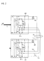
- FIG. 3 shows the detailed circuit arrangements of the two Scanning units AE1 and AE2 during the data transmission shown.
- the second scanning unit is AE2 with the downstream one - Not shown - connected to the evaluation unit; in connection with the present invention is only the power supply new, second scanning unit AE2 via the two lines + 5V, GND from Importance.
- the transistor T2 On the side of the second scanning unit AE2, the transistor T2 is turned on for data transmission. The basis of this is a resistor at + 5V; the emitter on GND. The line GND * is identical to GND up to 0.1V.
- the switching element SE2 5 At the control input of the switching element SE2 5 (not shown in FIG. 2) there is a logic LOW level, which causes the switching element SE2 5 to remain open. The two other switching elements SE2 2 and SE2 3 therefore remain closed.
- the address lines A0 2 , A1 2 , TEST 2 and A2 2 of the memory unit MEM2 are each at a logic LOW level. A sufficient power supply to the memory unit MEM2 is thus ensured, among other things, by the circuitry explained.
- the scanning unit AE1 to be exchanged is connected to the scanning unit AE2 via the sub-lines TL1-TL4 of the data transmission line DL.
- the connection variant shown ensures that the scanning unit AE1 is not connected to GND but only to GND *. Due to the selected component configuration, there is a resistance of approx. 300 ⁇ between + 5V and GND, which in turn means that all GND connections have a potential of almost + 5V. This in turn has the effect that the switching element SE1 1 designed as transistor T1 blocks in the first scanning unit AE1. A logic HIGH level is consequently present at the control input of the switching element SE1 5 , so that the switching element SE1 5 is closed.
- the address lines A0 1 , A1 1 and TEST 1 of the memory unit MEM1 are in turn all at a logic LOW level.
- Address line A2 1 is at a logic HIGH level in this state due to the selected wiring.
- the two memory units MEM1, MEM2 can therefore be differentiated in the above-mentioned method step S3 via the different levels of the address lines A2 1 (LOW) and A2 2 (HIGH).
- the circuit arrangement described also ensures that in the case the data transmission, the current consumption is only about the current consumption a storage unit and the current consumption of the switching elements increases. This is important insofar as the subordinate evaluation unit, the usually ensures the power supply of the scanning units, only is designed to supply a single scanning unit.
Landscapes
- Physics & Mathematics (AREA)
- General Physics & Mathematics (AREA)
- Engineering & Computer Science (AREA)
- Automation & Control Theory (AREA)
- Arrangements For Transmission Of Measured Signals (AREA)
- Small-Scale Networks (AREA)
- Transmission And Conversion Of Sensor Element Output (AREA)
- Time-Division Multiplex Systems (AREA)
Abstract
Description
- Figur 1
- eine schematische Prinzipskizze einer Positionsmeßeinrichtung;
- Figur 2
- eine schematische Darstellung einer ersten und zweiten Abtasteinheit, die gegeneinander ausgetauscht werden;
- Figur 3
- die detaillierten Schaltungsanordnungen zweier Abtasteinheiten während der Datenübertragung;
- Figur 4
- ein Flußdiagramm zur Erläuterung eines Ausführungsbeispieles des erfindungsgemäßen Verfahrens.
Die Prozessoreinheiten CPU1, CPU2 dienen dabei jeweils u.a. zur Synchronisation bzw. Steuerung der Signalverarbeitungsabläufe in den beiden Abtasteinheiten AE1, AE2. In den Signalverarbeitungseinheiten SVE1, SVE2 werden die jeweils detektierten Abtastsignale verarbeitetet und zur Signalübertragung an die Auswerteeinheit geeignet aufbereitet. In den beschreib- und auslesbaren Speichereinheiten MEM1, MEM2 wiederum werden verschiedenste spezifische Daten der jeweiligen Positionsmeßeinrichtung abgespeichert, die zum Betrieb der Positionsmeßeinrichtung erforderlich sind. Die Speichereinheiten MEM1, MEM2 sind beispielsweise als EEPROMS ausgebildet. Bei den erwähnten Daten kann es sich etwa um Daten bzgl. des mit der jeweiligen Abtasteinheit AE1, AE2 abzutastenden Meßteilungsabschnittes einer absoluten Positionsmeßeinrichtung handeln; desweiteren können maschinenspezifische Daten ebenso darin abgelegt werden, wie etwa Angaben zur Taktanzahl, Nullpunkteinstellung uvm.. Im Zusammenhang mit dem bislang erläuterten Aufbau der Abtasteinheiten und den eingesetzten Speichereinheiten sei im übrigen ergänzend auf die EP 0 660 209 B1 der Anmelderin verwiesen. Die Funktion und Bedeutung der verschiedenen Schaltelemente SE11, SE12, SE13, SE14, SE21, SE22, SE23, SE24 wird im Verlauf der nachfolgenden Beschreibung des erfindungsgemäßen Verfahrens bzw. der erfindungsgemäßen Anordnung anhand von Figur 4 und Figur 3 noch detaillierter erläutert.
Claims (18)
- Verfahren zur Datenübertragung zwischen Speichereinheiten (MEM1, MEM2) einer oder mehrerer Positionsmeßeinrichtungen, wobei in den Speichereinheiten (MEM1, MEM2) jeweils spezifische Daten der Positionsmeßeinrichtung abspeicherbar sind und über eine Datenübertragungsleitung (DL) eine Übertragung von Daten aus einer ersten Speichereinheit (MEM1) in eine zweite Speichereinheit (MEM2) erfolgt, so daß nach der erfolgten Datenübertragung in der zweiten Speichereinheit (MEM2) zumindest teilweise die spezifischen Daten der ersten Speichereinheit (MEM1) enthalten sind.
- Verfahren nach Anspruch 1, wobei die Übertragung der Daten automatisch erfolgt, sobald erfolgreich überprüft wurde, ob ein Zugriff auf die erste Speichereinheit (MEM1) mit darin abgespeicherten Daten möglich ist.
- Verfahren nach Anspruch 1, wobei über Anzeigemittel (AM1, AM2) angezeigt wird, ob die Datenübertragung korrekt verlaufen ist.
- Verfahren nach Anspruch 3, wobei die Anzeigemittel (AM1, AM2) als visuelle Anzeigemittel in Form mindestens einer LED ausgebildet sind, die in die Datenübertragungsleitung (DL) integriert sind.
- Verfahren nach Anspruch 4, wobei eine korrekte Datenübertragung durch dauerhaftes Einschalten der LED visualisiert wird, während eine nicht-korrekte Datenübertragung durch Blinken der LED visualisiert wird.
- Verfahren nach Anspruch 5, wobei im Fall der nicht-korrekten Datenübertragung mehrere Blinkmodi verfügbar sind, denen jeweils verschiedene Fehlerarten zugeordnet sind.
- Verfahren nach Anspruch 3, wobei über die Anzeigemittel (AM1, AM2) auch die Art eines eventuell aufgetretenen Fehlers bei der Datenübertragung angezeigt wird.
- Verfahren nach Anspruch 2, wobei die Speichereinheiten (MEM1, MEM2) jeweils in einer ersten und zweiten Abtasteinheit (AE1, AE2) einer Positionsmeßeinrichtung angeordnet sind.
- Verfahren nach Anspruch 9, wobei im Fall der möglichen Datenübertragung auf Seiten der ersten Abtasteinheit (AE1) sichergestellt ist, daß lediglich die erste Speichereinheit (MEM1) und ein oder mehrere Schaltelemente (SE11 - SE15) mit Strom versorgt werden.
- Verfahren nach Anspruch 8 mit folgenden Verfahrensschritten:a) Verbinden der ersten und zweiten Abtasteinheit (AE1, AE2) mittels einer Datenübertragungsleitung (DL);b) Verbinden der zweiten Abtasteinheit (AE2) mit einer Versorgungsleitung (L);c) Überprüfen, ob von der zweiten Abtasteinheit (AE2) aus der Zugriff auf die erste Speichereinheit (MEM1) mit darin abgespeicherten Daten möglich ist;d) zumindest teilweises Übertragen der Daten aus der ersten Speichereinheit (MEM1) in die zweite Speichereinheit (MEM2), sofern in Schritt c) festgestellt wurde, daß ein Zugriff auf die erste Speichereinheit (MEM1) möglich ist;e) Aktivieren von Anzeigemitteln (AM1, AM2), die anzeigen, ob die Datenübertragung korrekt oder nicht-korrekt verlaufen ist.
- Anordnung zur Datenübertragung zwischen Speichereinheiten (MEM1, MEM2) einer oder mehrerer Positionsmeßeinrichtungen, wobei in den Speichereinheiten (MEM1, MEM2) jeweils spezifische Daten der Positionsmeßeinrichtung abspeicherbar sind und die Speichereinheiten (MEM1, MEM2) mittels einer Datenübertragungsleitung (DL) miteinander verbunden sind, über die eine Übertragung von Daten aus einer ersten Speichereinheit (MEM1) in eine zweite Speichereinheit (MEM2) erfolgt, so daß nach der erfolgten Datenübertragung in der zweiten Speichereinheit (MEM2) zumindest teilweise die spezifischen Daten der ersten Speichereinheit (MEM1) enthalten sind.
- Anordnung nach Anspruch 11, die mindestens ein Anzeigemittel (AM1, AM2) umfaßt, welches anzeigt, ob die Datenübertragung korrekt verlaufen ist.
- Anordnung nach Anspruch 12, wobei das Anzeigemittel (AM1, AM2) als visuelles Anzeigemittel in Form mindestens einer in die Datenübertragungsleitung (DL) integrierten LED ausgebildet ist.
- Anordnung nach Anspruch 11, wobei die Speichereinheiten (MEM1, MEM2) in einer ersten und zweiten Abtasteinheit (AE1, AE2) angeordnet sind.
- Anordnung nach Anspruch 14, wobei die Abtasteinheiten (AE1, AE2) desweiteren jeweils eine Prozessoreinheit (CPU1, CPU2) umfassen.
- Anordnung nach Anspruch 12 und 15, wobei die Prozessoreinheit (CPU1, CPU2) mit dem Anzeigemittel (AM1, AM2) verbunden ist und die Prozessoreinheit (CPU1, CPU2) derart ausgebildet ist, daß diese in Abhängigkeit vom korrekten oder nicht-korrekten Verlauf der Datenübertragung das Anzeigemittel (AM1, AM2) aktiviert.
- Anordnung nach Anspruch 14, wobei die Abtasteinheiten (AE1, AE2) jeweils lösbare elektrische Verbindungselemente für die Datenübertragungsleitung (DL) aufweisen.
- Anordnung nach Anspruch 14, die ferner mehrere Schaltelemente (SE11 - SE15, SE21 - SE25) in den Abtasteinheiten (AE1, AE2) umfaßt, die derart ansteuerbar sind, daß zumindest die erste und zweite Speichereinheit (MEM1, MEM2) in den beiden Abtasteinheiten (AE1, AE2) während der Datenübertragung mit Strom versorgbar ist.
Applications Claiming Priority (2)
| Application Number | Priority Date | Filing Date | Title |
|---|---|---|---|
| DE19933963 | 1999-07-20 | ||
| DE19933963A DE19933963A1 (de) | 1999-07-20 | 1999-07-20 | Verfahren und Anordnung zur Datenübertragung zwischen verschiedenen Speichereinheiten von Positionsmeßeinrichtungen |
Publications (3)
| Publication Number | Publication Date |
|---|---|
| EP1071019A2 true EP1071019A2 (de) | 2001-01-24 |
| EP1071019A3 EP1071019A3 (de) | 2004-02-04 |
| EP1071019B1 EP1071019B1 (de) | 2006-03-29 |
Family
ID=7915397
Family Applications (1)
| Application Number | Title | Priority Date | Filing Date |
|---|---|---|---|
| EP00114703A Expired - Lifetime EP1071019B1 (de) | 1999-07-20 | 2000-07-08 | Verfahren und Anordnung zur Datenübertragung zwischen verschiedenen Speichereinheiten von Positionsmesseinrichtungen |
Country Status (6)
| Country | Link |
|---|---|
| US (1) | US6738802B1 (de) |
| EP (1) | EP1071019B1 (de) |
| JP (1) | JP4780820B2 (de) |
| AT (1) | ATE322042T1 (de) |
| DE (2) | DE19933963A1 (de) |
| ES (1) | ES2261126T3 (de) |
Cited By (1)
| Publication number | Priority date | Publication date | Assignee | Title |
|---|---|---|---|---|
| EP1731976A3 (de) * | 2005-06-03 | 2007-12-26 | Bomag Gmbh | Konfigurationsverfahren für Steuergeräte |
Families Citing this family (3)
| Publication number | Priority date | Publication date | Assignee | Title |
|---|---|---|---|---|
| DE10244923B4 (de) * | 2002-09-25 | 2015-02-26 | Dr. Johannes Heidenhain Gmbh | Positionsmesseinrichtung und Verfahren zur Positionsbestimmung |
| US20060174051A1 (en) * | 2005-02-02 | 2006-08-03 | Honeywell International Inc. | Method and apparatus for a redundancy approach in a processor based controller design |
| EP2138806A1 (de) * | 2008-06-27 | 2009-12-30 | SICK STEGMANN GmbH | Positionsmessvorrichtung |
Family Cites Families (26)
| Publication number | Priority date | Publication date | Assignee | Title |
|---|---|---|---|---|
| US3020457A (en) * | 1951-10-11 | 1962-02-06 | Robert C Kelley | Remote control servosystem |
| DE1925427A1 (de) * | 1968-05-25 | 1970-01-15 | Fujitsu Ltd | Datenuebertragungsvorrichtung zum UEbertragen von Daten zwischen Informationsspeichern |
| EP0088789B1 (de) * | 1981-09-18 | 1987-08-05 | CHRISTIAN ROVSING A/S af 1984 | Multiprozessor-rechnersystem |
| DE3318977A1 (de) * | 1983-05-25 | 1984-11-29 | Siemens AG, 1000 Berlin und 8000 München | Messwertaufnehmer mit einem betriebsdaten enthaltenden informationstraeger |
| JPS63101931A (ja) * | 1986-10-17 | 1988-05-06 | Minolta Camera Co Ltd | プログラム制御方式 |
| DE3641631A1 (de) * | 1986-12-04 | 1988-06-16 | Licentia Gmbh | Verfahren zur vermeidung der verwertung von fehlerhaften daten bei einer datenuebertragung auf ein fahrzeug |
| JPH01122797U (de) * | 1988-02-17 | 1989-08-21 | ||
| US5109485A (en) * | 1988-08-30 | 1992-04-28 | Ncr Corporation | Method for transferring data between memories |
| US5123017A (en) * | 1989-09-29 | 1992-06-16 | The United States Of America As Represented By The Administrator Of The National Aeronautics And Space Administration | Remote maintenance monitoring system |
| US5675672A (en) * | 1990-06-26 | 1997-10-07 | Seiko Epson Corporation | Two dimensional linker for character string data |
| US5392447A (en) * | 1992-01-10 | 1995-02-21 | Eastman Kodak Compay | Image-based electronic pocket organizer with integral scanning unit |
| JPH0766887A (ja) * | 1993-08-24 | 1995-03-10 | Hitachi Home Tec Ltd | 自動通報システム |
| DE4342377B4 (de) * | 1993-12-13 | 2010-08-12 | Dr. Johannes Heidenhain Gmbh | Anordnung und Verfahren zur seriellen Datenübertragung einer Positionsmeßeinrichtung |
| US5629868A (en) * | 1994-02-07 | 1997-05-13 | Le Groupe Videotron Ltee | Method of programming local control |
| SE502364C2 (sv) * | 1994-08-11 | 1995-10-09 | Kvaser Consultant Ab | Förfarande och anordning vid modul anslutbar till seriellt och digitalt nätverksystem |
| US5491540A (en) * | 1994-12-22 | 1996-02-13 | Hewlett-Packard Company | Replacement part with integral memory for usage and calibration data |
| JPH09326871A (ja) * | 1996-06-05 | 1997-12-16 | Matsushita Electric Ind Co Ltd | 伝送制御装置 |
| JP3758754B2 (ja) * | 1996-08-02 | 2006-03-22 | 富士ゼロックス株式会社 | 情報蓄積再生装置および情報蓄積再生方法 |
| DE19639316A1 (de) * | 1996-09-25 | 1998-03-26 | Heidenhain Gmbh Dr Johannes | Positionsmeßsystem und Meßverfahren |
| US5896492A (en) * | 1996-10-28 | 1999-04-20 | Sun Microsystems, Inc. | Maintaining data coherency between a primary memory controller and a backup memory controller |
| DE19711216C1 (de) * | 1997-03-18 | 1998-05-07 | Heidenhain Gmbh Dr Johannes | Verfahren und Vorrichtung zur Übertragung von Daten zwischen einer Positionsmeßeinrichtung und einer Auswerteeinheit |
| DE19711218C1 (de) * | 1997-03-18 | 1998-04-09 | Heidenhain Gmbh Dr Johannes | Verfahren und Vorrichtung zur Übertragung von Daten zwischen einer Positionsmeßeinrichtung und einer Auswerteeinheit |
| DE19711215C1 (de) * | 1997-03-18 | 1998-05-07 | Heidenhain Gmbh Dr Johannes | Verfahren und Vorrichtung zur Umschaltung zwischen verschiedenen Ausgangssignal-Arten einer Positionsmeßeinrichtung |
| US5933347A (en) * | 1997-06-13 | 1999-08-03 | Allen-Bradley Company Llc | Industrial controller with program synchronized updating of back-up controller |
| AU8928998A (en) * | 1997-10-15 | 1999-05-06 | Pittway Corporation | Apparatus for and method of displaying information |
| US6170044B1 (en) * | 1997-12-19 | 2001-01-02 | Honeywell Inc. | Systems and methods for synchronizing redundant controllers with minimal control disruption |
-
1999
- 1999-07-20 DE DE19933963A patent/DE19933963A1/de not_active Withdrawn
-
2000
- 2000-07-08 AT AT00114703T patent/ATE322042T1/de not_active IP Right Cessation
- 2000-07-08 DE DE50012465T patent/DE50012465D1/de not_active Expired - Lifetime
- 2000-07-08 ES ES00114703T patent/ES2261126T3/es not_active Expired - Lifetime
- 2000-07-08 EP EP00114703A patent/EP1071019B1/de not_active Expired - Lifetime
- 2000-07-17 JP JP2000215787A patent/JP4780820B2/ja not_active Expired - Fee Related
- 2000-07-20 US US09/620,158 patent/US6738802B1/en not_active Expired - Fee Related
Cited By (2)
| Publication number | Priority date | Publication date | Assignee | Title |
|---|---|---|---|---|
| EP1731976A3 (de) * | 2005-06-03 | 2007-12-26 | Bomag Gmbh | Konfigurationsverfahren für Steuergeräte |
| US8555375B2 (en) | 2005-06-03 | 2013-10-08 | Bomag Gmbh | Configuration method for control units |
Also Published As
| Publication number | Publication date |
|---|---|
| JP2001056897A (ja) | 2001-02-27 |
| ES2261126T3 (es) | 2006-11-16 |
| DE19933963A1 (de) | 2001-02-01 |
| US6738802B1 (en) | 2004-05-18 |
| EP1071019A3 (de) | 2004-02-04 |
| JP4780820B2 (ja) | 2011-09-28 |
| DE50012465D1 (de) | 2006-05-18 |
| ATE322042T1 (de) | 2006-04-15 |
| EP1071019B1 (de) | 2006-03-29 |
Similar Documents
| Publication | Publication Date | Title |
|---|---|---|
| DE3111852C2 (de) | ||
| EP3961318B1 (de) | Verfahren zur konfiguration einer modularen sicherheitsschaltvorrichtung | |
| DE19701310B4 (de) | Vorrichtung und Verfahren zur Datenübertragung und zur Umschaltung zwischen verschiedenen Betriebsmodi eines Meßwertaufnehmers | |
| EP0629773A1 (de) | Diagnoseverfahren für Kraftfahrzeuge zum Überprüfen elektronisch gesteuerter Systeme | |
| EP0997800A1 (de) | Gerät zur Verwendung in einem industriellen Prozess und Anlage mit solchen Geräten sowie Verfahren zum Simulieren des Betriebs einer solchen Anlage | |
| DE3806794A1 (de) | Mehrfunktionspruefvorrichtung zur feststellung von stoerungen | |
| DE3702408C2 (de) | ||
| DE3727549C2 (de) | ||
| DE3419273C2 (de) | ||
| DE102006005365A1 (de) | Verfahren zum Aktualisieren der Firmware von Feldgeräten | |
| EP1071019B1 (de) | Verfahren und Anordnung zur Datenübertragung zwischen verschiedenen Speichereinheiten von Positionsmesseinrichtungen | |
| EP0436818B1 (de) | Diagnosesystem für eine digitale Steuereinrichtung | |
| EP4432034B1 (de) | Verfahren und system zur erkennung einer konfiguration einer modularen sicherheitssteuerung | |
| DE10147166A1 (de) | System und Verfahren zur Programmierung eines Automatisierungssystems basierend auf Impulsdiagrammen | |
| DE19607101A1 (de) | Elektronisches Gerät und Einrichtung zur Datenübertragung zwischen zwei gleichartig aufgebauten elektronischen Geräten | |
| DE4026581A1 (de) | Integriertes steuerungssystem fuer eine textilmaschine mit einer vielzahl von separat angetriebenen spindeln | |
| DE2005884A1 (de) | Vorrichtung und Verfahren zur Feststellung von Fehlern in elektronischen Datenverarbeitungsanlagen | |
| EP1131685B1 (de) | Verfahren zum überprüfen einer ausgabeeinheit | |
| DE3413330A1 (de) | Verfahren zur ueberwachung und lokalisierung eines fehlers der fabrikationszyklen einer automatischen fertigungsstrasse und vorrichtung zu seiner durchfuehrung | |
| DE3638256A1 (de) | Schaltung zur erzeugung kuenstlicher fehler fuer eine datenverarbeitungsanlage | |
| EP0544148B1 (de) | Verfahren zum Programmieren von programmierbaren integrierten Schaltkreisen | |
| DE29914463U1 (de) | Projektierungseinheit für korrespondierende Diagnosedatensätze eines Systems mit Steuerungseinheit und Bedien- und/oder Beobachtungseinheit, und System mit Mitteln zum Versionsvergleich von zugeordneten Diagnosedatensätzen | |
| DE10226876B4 (de) | Vorrichtung und Verfahren zur Überprüfung eines Bussystems | |
| DE102004033266A1 (de) | Positionsmesseinrichtung und Verfahren zur Positionsmessung | |
| EP0645710A2 (de) | Verfahren zur Funktionsprüfung signaltechnisch nicht sicherer Speicher für mindestens zweikanalig abgespeicherte Nutzdaten und Einrichtung zur Durchführung des Verfahrens |
Legal Events
| Date | Code | Title | Description |
|---|---|---|---|
| PUAI | Public reference made under article 153(3) epc to a published international application that has entered the european phase |
Free format text: ORIGINAL CODE: 0009012 |
|
| AK | Designated contracting states |
Kind code of ref document: A2 Designated state(s): AT BE CH CY DE DK ES FI FR GB GR IE IT LI LU MC NL PT SE |
|
| AX | Request for extension of the european patent |
Free format text: AL;LT;LV;MK;RO;SI |
|
| PUAL | Search report despatched |
Free format text: ORIGINAL CODE: 0009013 |
|
| AK | Designated contracting states |
Kind code of ref document: A3 Designated state(s): AT BE CH CY DE DK ES FI FR GB GR IE IT LI LU MC NL PT SE |
|
| AX | Request for extension of the european patent |
Extension state: AL LT LV MK RO SI |
|
| RIC1 | Information provided on ipc code assigned before grant |
Ipc: 7G 05B 19/00 B Ipc: 7G 06F 13/00 A |
|
| 17P | Request for examination filed |
Effective date: 20040804 |
|
| AKX | Designation fees paid |
Designated state(s): AT BE CH CY DE DK ES FI FR GB GR IE IT LI LU MC NL PT SE |
|
| 17Q | First examination report despatched |
Effective date: 20050329 |
|
| GRAP | Despatch of communication of intention to grant a patent |
Free format text: ORIGINAL CODE: EPIDOSNIGR1 |
|
| GRAS | Grant fee paid |
Free format text: ORIGINAL CODE: EPIDOSNIGR3 |
|
| GRAA | (expected) grant |
Free format text: ORIGINAL CODE: 0009210 |
|
| AK | Designated contracting states |
Kind code of ref document: B1 Designated state(s): AT BE CH CY DE DK ES FI FR GB GR IE IT LI LU MC NL PT SE |
|
| PG25 | Lapsed in a contracting state [announced via postgrant information from national office to epo] |
Ref country code: IE Free format text: LAPSE BECAUSE OF FAILURE TO SUBMIT A TRANSLATION OF THE DESCRIPTION OR TO PAY THE FEE WITHIN THE PRESCRIBED TIME-LIMIT Effective date: 20060329 Ref country code: NL Free format text: LAPSE BECAUSE OF FAILURE TO SUBMIT A TRANSLATION OF THE DESCRIPTION OR TO PAY THE FEE WITHIN THE PRESCRIBED TIME-LIMIT Effective date: 20060329 |
|
| REG | Reference to a national code |
Ref country code: GB Ref legal event code: FG4D Free format text: NOT ENGLISH |
|
| REG | Reference to a national code |
Ref country code: CH Ref legal event code: NV Representative=s name: TROESCH SCHEIDEGGER WERNER AG Ref country code: CH Ref legal event code: EP |
|
| GBT | Gb: translation of ep patent filed (gb section 77(6)(a)/1977) |
Effective date: 20060329 |
|
| REG | Reference to a national code |
Ref country code: IE Ref legal event code: FG4D Free format text: LANGUAGE OF EP DOCUMENT: GERMAN |
|
| REF | Corresponds to: |
Ref document number: 50012465 Country of ref document: DE Date of ref document: 20060518 Kind code of ref document: P |
|
| PG25 | Lapsed in a contracting state [announced via postgrant information from national office to epo] |
Ref country code: DK Free format text: LAPSE BECAUSE OF FAILURE TO SUBMIT A TRANSLATION OF THE DESCRIPTION OR TO PAY THE FEE WITHIN THE PRESCRIBED TIME-LIMIT Effective date: 20060629 Ref country code: SE Free format text: LAPSE BECAUSE OF FAILURE TO SUBMIT A TRANSLATION OF THE DESCRIPTION OR TO PAY THE FEE WITHIN THE PRESCRIBED TIME-LIMIT Effective date: 20060629 |
|
| PG25 | Lapsed in a contracting state [announced via postgrant information from national office to epo] |
Ref country code: BE Free format text: LAPSE BECAUSE OF NON-PAYMENT OF DUE FEES Effective date: 20060731 Ref country code: MC Free format text: LAPSE BECAUSE OF NON-PAYMENT OF DUE FEES Effective date: 20060731 |
|
| PG25 | Lapsed in a contracting state [announced via postgrant information from national office to epo] |
Ref country code: PT Free format text: LAPSE BECAUSE OF FAILURE TO SUBMIT A TRANSLATION OF THE DESCRIPTION OR TO PAY THE FEE WITHIN THE PRESCRIBED TIME-LIMIT Effective date: 20060829 |
|
| NLV1 | Nl: lapsed or annulled due to failure to fulfill the requirements of art. 29p and 29m of the patents act | ||
| REG | Reference to a national code |
Ref country code: IE Ref legal event code: FD4D |
|
| REG | Reference to a national code |
Ref country code: ES Ref legal event code: FG2A Ref document number: 2261126 Country of ref document: ES Kind code of ref document: T3 |
|
| PLBE | No opposition filed within time limit |
Free format text: ORIGINAL CODE: 0009261 |
|
| STAA | Information on the status of an ep patent application or granted ep patent |
Free format text: STATUS: NO OPPOSITION FILED WITHIN TIME LIMIT |
|
| 26N | No opposition filed |
Effective date: 20070102 |
|
| EN | Fr: translation not filed | ||
| PG25 | Lapsed in a contracting state [announced via postgrant information from national office to epo] |
Ref country code: AT Free format text: LAPSE BECAUSE OF NON-PAYMENT OF DUE FEES Effective date: 20060708 |
|
| BERE | Be: lapsed |
Owner name: DR. JOHANNES HEIDENHAIN G.M.B.H. Effective date: 20060731 |
|
| PG25 | Lapsed in a contracting state [announced via postgrant information from national office to epo] |
Ref country code: FR Free format text: LAPSE BECAUSE OF FAILURE TO SUBMIT A TRANSLATION OF THE DESCRIPTION OR TO PAY THE FEE WITHIN THE PRESCRIBED TIME-LIMIT Effective date: 20070309 Ref country code: GR Free format text: LAPSE BECAUSE OF FAILURE TO SUBMIT A TRANSLATION OF THE DESCRIPTION OR TO PAY THE FEE WITHIN THE PRESCRIBED TIME-LIMIT Effective date: 20060630 |
|
| PG25 | Lapsed in a contracting state [announced via postgrant information from national office to epo] |
Ref country code: FI Free format text: LAPSE BECAUSE OF FAILURE TO SUBMIT A TRANSLATION OF THE DESCRIPTION OR TO PAY THE FEE WITHIN THE PRESCRIBED TIME-LIMIT Effective date: 20060329 |
|
| PG25 | Lapsed in a contracting state [announced via postgrant information from national office to epo] |
Ref country code: LU Free format text: LAPSE BECAUSE OF NON-PAYMENT OF DUE FEES Effective date: 20060708 |
|
| PG25 | Lapsed in a contracting state [announced via postgrant information from national office to epo] |
Ref country code: FR Free format text: LAPSE BECAUSE OF FAILURE TO SUBMIT A TRANSLATION OF THE DESCRIPTION OR TO PAY THE FEE WITHIN THE PRESCRIBED TIME-LIMIT Effective date: 20060329 Ref country code: CY Free format text: LAPSE BECAUSE OF FAILURE TO SUBMIT A TRANSLATION OF THE DESCRIPTION OR TO PAY THE FEE WITHIN THE PRESCRIBED TIME-LIMIT Effective date: 20060329 |
|
| PGFP | Annual fee paid to national office [announced via postgrant information from national office to epo] |
Ref country code: CH Payment date: 20110725 Year of fee payment: 12 |
|
| PGFP | Annual fee paid to national office [announced via postgrant information from national office to epo] |
Ref country code: IT Payment date: 20110722 Year of fee payment: 12 |
|
| REG | Reference to a national code |
Ref country code: CH Ref legal event code: PL |
|
| PG25 | Lapsed in a contracting state [announced via postgrant information from national office to epo] |
Ref country code: LI Free format text: LAPSE BECAUSE OF NON-PAYMENT OF DUE FEES Effective date: 20120731 Ref country code: CH Free format text: LAPSE BECAUSE OF NON-PAYMENT OF DUE FEES Effective date: 20120731 |
|
| PG25 | Lapsed in a contracting state [announced via postgrant information from national office to epo] |
Ref country code: IT Free format text: LAPSE BECAUSE OF NON-PAYMENT OF DUE FEES Effective date: 20120708 |
|
| PGFP | Annual fee paid to national office [announced via postgrant information from national office to epo] |
Ref country code: ES Payment date: 20130729 Year of fee payment: 14 |
|
| PGFP | Annual fee paid to national office [announced via postgrant information from national office to epo] |
Ref country code: GB Payment date: 20130719 Year of fee payment: 14 |
|
| PGFP | Annual fee paid to national office [announced via postgrant information from national office to epo] |
Ref country code: DE Payment date: 20140721 Year of fee payment: 15 |
|
| GBPC | Gb: european patent ceased through non-payment of renewal fee |
Effective date: 20140708 |
|
| PG25 | Lapsed in a contracting state [announced via postgrant information from national office to epo] |
Ref country code: GB Free format text: LAPSE BECAUSE OF NON-PAYMENT OF DUE FEES Effective date: 20140708 |
|
| REG | Reference to a national code |
Ref country code: ES Ref legal event code: FD2A Effective date: 20150828 |
|
| PG25 | Lapsed in a contracting state [announced via postgrant information from national office to epo] |
Ref country code: ES Free format text: LAPSE BECAUSE OF NON-PAYMENT OF DUE FEES Effective date: 20140709 |
|
| REG | Reference to a national code |
Ref country code: DE Ref legal event code: R119 Ref document number: 50012465 Country of ref document: DE |
|
| PG25 | Lapsed in a contracting state [announced via postgrant information from national office to epo] |
Ref country code: DE Free format text: LAPSE BECAUSE OF NON-PAYMENT OF DUE FEES Effective date: 20160202 |