EP1070766A1 - Substrate for displays and method for its manufacture - Google Patents
Substrate for displays and method for its manufacture Download PDFInfo
- Publication number
- EP1070766A1 EP1070766A1 EP00402066A EP00402066A EP1070766A1 EP 1070766 A1 EP1070766 A1 EP 1070766A1 EP 00402066 A EP00402066 A EP 00402066A EP 00402066 A EP00402066 A EP 00402066A EP 1070766 A1 EP1070766 A1 EP 1070766A1
- Authority
- EP
- European Patent Office
- Prior art keywords
- substrate
- target
- thin film
- displays
- electrical resistance
- Prior art date
- Legal status (The legal status is an assumption and is not a legal conclusion. Google has not performed a legal analysis and makes no representation as to the accuracy of the status listed.)
- Withdrawn
Links
Images


Classifications
-
- C—CHEMISTRY; METALLURGY
- C03—GLASS; MINERAL OR SLAG WOOL
- C03C—CHEMICAL COMPOSITION OF GLASSES, GLAZES OR VITREOUS ENAMELS; SURFACE TREATMENT OF GLASS; SURFACE TREATMENT OF FIBRES OR FILAMENTS MADE FROM GLASS, MINERALS OR SLAGS; JOINING GLASS TO GLASS OR OTHER MATERIALS
- C03C17/00—Surface treatment of glass, not in the form of fibres or filaments, by coating
- C03C17/34—Surface treatment of glass, not in the form of fibres or filaments, by coating with at least two coatings having different compositions
- C03C17/3411—Surface treatment of glass, not in the form of fibres or filaments, by coating with at least two coatings having different compositions with at least two coatings of inorganic materials
- C03C17/3429—Surface treatment of glass, not in the form of fibres or filaments, by coating with at least two coatings having different compositions with at least two coatings of inorganic materials at least one of the coatings being a non-oxide coating
- C03C17/3435—Surface treatment of glass, not in the form of fibres or filaments, by coating with at least two coatings having different compositions with at least two coatings of inorganic materials at least one of the coatings being a non-oxide coating comprising a nitride, oxynitride, boronitride or carbonitride
-
- C—CHEMISTRY; METALLURGY
- C23—COATING METALLIC MATERIAL; COATING MATERIAL WITH METALLIC MATERIAL; CHEMICAL SURFACE TREATMENT; DIFFUSION TREATMENT OF METALLIC MATERIAL; COATING BY VACUUM EVAPORATION, BY SPUTTERING, BY ION IMPLANTATION OR BY CHEMICAL VAPOUR DEPOSITION, IN GENERAL; INHIBITING CORROSION OF METALLIC MATERIAL OR INCRUSTATION IN GENERAL
- C23C—COATING METALLIC MATERIAL; COATING MATERIAL WITH METALLIC MATERIAL; SURFACE TREATMENT OF METALLIC MATERIAL BY DIFFUSION INTO THE SURFACE, BY CHEMICAL CONVERSION OR SUBSTITUTION; COATING BY VACUUM EVAPORATION, BY SPUTTERING, BY ION IMPLANTATION OR BY CHEMICAL VAPOUR DEPOSITION, IN GENERAL
- C23C14/00—Coating by vacuum evaporation, by sputtering or by ion implantation of the coating forming material
- C23C14/06—Coating by vacuum evaporation, by sputtering or by ion implantation of the coating forming material characterised by the coating material
- C23C14/0676—Oxynitrides
-
- C—CHEMISTRY; METALLURGY
- C23—COATING METALLIC MATERIAL; COATING MATERIAL WITH METALLIC MATERIAL; CHEMICAL SURFACE TREATMENT; DIFFUSION TREATMENT OF METALLIC MATERIAL; COATING BY VACUUM EVAPORATION, BY SPUTTERING, BY ION IMPLANTATION OR BY CHEMICAL VAPOUR DEPOSITION, IN GENERAL; INHIBITING CORROSION OF METALLIC MATERIAL OR INCRUSTATION IN GENERAL
- C23C—COATING METALLIC MATERIAL; COATING MATERIAL WITH METALLIC MATERIAL; SURFACE TREATMENT OF METALLIC MATERIAL BY DIFFUSION INTO THE SURFACE, BY CHEMICAL CONVERSION OR SUBSTITUTION; COATING BY VACUUM EVAPORATION, BY SPUTTERING, BY ION IMPLANTATION OR BY CHEMICAL VAPOUR DEPOSITION, IN GENERAL
- C23C14/00—Coating by vacuum evaporation, by sputtering or by ion implantation of the coating forming material
- C23C14/22—Coating by vacuum evaporation, by sputtering or by ion implantation of the coating forming material characterised by the process of coating
- C23C14/34—Sputtering
- C23C14/3407—Cathode assembly for sputtering apparatus, e.g. Target
- C23C14/3414—Metallurgical or chemical aspects of target preparation, e.g. casting, powder metallurgy
Definitions
- the present invention relates to a method of manufacturing a substrate for displays and a substrate for displays manufactured by the same method, and more particularly, to a method of manufacturing a substrate for displays, which has a film formed thereon to prevent electrification of the substrate surface, and a substrate for displays manufactured by the same method.
- Conventional substrates for displays for use in field emission displays including surface-conduction electron-emitter devices (SED), and plasma display panels (PDP) had the disadvantage that the substrate surface is prone to electrification attributable to the driving method of the FED or PDP, i.e., due to application of a high electric field between the substrates for generation of light or due to exposure of the surface of the substrate to plasma.
- the electrification can cause generation of a spark, leading to a shortened service life of a display element.
- the electrification of the substrate surface depends on the surface electrical resistance of the substrate.
- a thin film of a metal oxynitride having a surface electrical resistance controlled to a desired value suitable for anti-electrification is formed by sputtering using a metal target in a mixture gas atmosphere of oxygen and nitrogen.
- the surface electrical resistance of the thin film is controlled to a desired value by changing the mixing ratio of oxygen and nitrogen in the mixture gas atmosphere.
- the present invention provides a method of manufacturing a substrate for displays, comprising the steps of preparing a target from a metal oxide, and forming a thin film of a metal oxynitride on a surface of the substrate by sputtering using the target in an atmosphere of a mixture gas of an inert gas and nitrogen, a mixing ratio of the inert gas and nitrogen in the atmosphere being adjusted such that the thin film has a desired surface electrical resistance.
- the method of the present invention it is possible to easily control the value of the surface electrical resistance of the anti-electrification thin film formed on the surface of the substrate to a desired value.
- the inert gas is contained in the atmosphere in an amount of 5 to 95 volume %.
- the desired surface electrical resistance is 1.0 x 10 8 to 1.0 x 10 2 ⁇ / ⁇ .
- the target is formed of at least two kinds of metal oxides.
- one kind of the two kinds of metal oxides is an oxide of an element selected from the group consisting of titanium and zirconium.
- the other kind of the two kinds of metal oxides is an oxide of an element selected from the group consisting of niobium, vanadium, tantalum, yttrium, and tungsten.
- one kind of the two kinds of metal oxides is contained in the target in an amount of 70 to 99.5 weight %.
- the other kind of the two kinds of metal oxides is contained in the target in an amount of 0.5 to 30 weight %.
- the method of manufacturing a substrate for displays further comprises the step of forming at least one anti-movable ion thermodiffusion film stacked on the thin film formed on the surface of the substrate.
- the anti-movable ion thermodiffusion film is formed of a compound selected from the group consisting of an oxide of silicon, an oxynitride of silicon, or a nitride of silicon.
- the anti-movable ion thermodiffusion film has a total film thickness of 20 to 1000nm.
- the present invention provides a substrate for displays manufactured by preparing a target from a metal oxide, and forming a thin film of a metal oxynitride on a surface of the substrate by sputtering using the target in an atmosphere of a mixture gas of an inert gas and nitrogen, a mixing ratio of said inert gas and nitrogen in said atmosphere being adjusted such that said thin film has a desired surface electrical resistance.
- the substrate for displays of the present invention no electrification of the substrate surface can occur, making it possible to obtain a substrate for displays at a low cost without shortening of the life of the display element.
- the present inventors conducted extensive studies on a method of manufacturing a substrate for displays, which includes forming a thin film of a metal oxynitride having a desired surface electrical resistance on a surface of the substrate by sputtering using a target in a gas atmosphere containing nitrogen.
- the inventors reached a finding that if the target is formed of a metal oxide, the gas atmosphere is formed of a mixture of an inert gas and nitrogen, and the mixing ratio of the inert gas and oxygen of the gas atmosphere is adjusted such that the thin film has a desired surface electrical resistance, the change of the surface electrical resistance of the anti-electrification thin film becomes moderate relative to the change in the mixing ratio of the inert gas and nitrogen, thus making it possible to easily control the surface electrical resistance of the thin film to a desired value
- the content of the inert gas in the gas atmosphere is 5 to 95 volume %, it is possible to form the thin film of a metal oxynitride on the surface of the substrate in a reliable manner.
- the present inventors also found that if the target is formed of at least two kinds of metal oxides, one of which is a metal oxide of either titanium or zirconium, and the other is a metal oxide of one of niobium, vanadium, tantalum, yttrium, and tungsten, and if the content of the former metal oxide is 70 to 99.5 weight %, and the content of the latter metal oxide is 0.5 to 30 weight %, then it is possible to control the value of the surface electrical resistance to a desired value in a more reliable manner.
- the thin film is formed on the surface of the substrate by sputtering using a titanium oxide-based target containing 0.5 to 30 weight % of niobium in an atmosphere of an argon and nitrogen mixture gas, it is possible to control the value of the surface electrical resistance in an especially reliable manner.
- the niobium oxide content is less than 0.5 weight %, a stable electric discharge cannot be conducted during sputtering.
- the electric conductivity of the target does not change significantly.
- the present invention is based upon the above findings.
- FIG. 1 is a sectional view of the field emission element.
- numeral 10 designates a glass substrate which has an element-formed surface on which a thin film 11 is formed by sputtering, to prevent electrification of the surface of the glass substrate 10.
- the substrate 10 is formed of soda-lime glass, and has a thickness of, for example, 3mm.
- the thin film 11 has a thickness of, for example, 10nm.
- the element electrodes 12 and 13 may be formed by a combination of a film forming technique such as CVD and a patterning technique such as photolithography and etching, or may be formed by a printing technique.
- the shape of the element electrodes 12 and 13 is designed according to the application of the field emission element.
- a conductive film 14 is formed between the element electrodes 12 and 13, by means of photolithography or etching.
- the conductive film 14 and the element electrodes 12 and 13 partially overlap with each other so that they are preferably electrically well connected to each other.
- An electron emitting part 15 having a higher electrical resistance than the conductive film 14 is formed in a part of the conductive film 14, by an electroforming method.
- the electron emitting part 15 and its neighboring area are coated with a thin film 16.
- the thin film 16, which is formed of carbon or a carbon compound, is formed after the formation of the electron emitting part 15, by an electric activation method.
- the thin film 11 is formed of at least two kinds of metal oxynitrides, one of which is a metal oxynitride of either titanium or zirconium (TiON, ZrON), and the other is a metal oxynitride of one of niobium, vanadium, tantalum, yttrium, and tungsten (NbON, VaON, TaON, YON, or WON).
- TiON, ZrON zirconium
- tungsten NbON, VaON, TaON, YON, or WON.
- the formation of the thin film 11 on the surface of the substrate 10 by sputtering is carried out using a metal oxide target in a gas atmosphere of a mixture of an inert gas and nitrogen, while the mixing ratio of the inert gas and nitrogen in the gas atmosphere is adjusted such that the thin film 14 exhibits a desired surface electrical resistance.
- the surface electrical resistance of the thin film 11 is in a range of 1.0 x10 8 to 1.0 x10 12 ⁇ / ⁇ . This range allows electric charges of the substrate surface to be dissipated, so that the shortening of the life of the display element due to the electrification of the substrate surface can be suppressed. That is, the display element can fully withstand practical use.
- the surface electrical resistance of the metal oxide target is 10 ⁇ / ⁇ or less. This enables the formation of the thin film 11 to be controlled in a reliable manner.
- the thin film 11 may be formed by stacking at least one alkali-ion passivation film 11b (anti-movable ion thermodiffusion film) containing a compound selected from the group consisting of SiO 2 an oxynitride of silicon (SiON), and a nitride of silicon, on the above described thin film ha formed of at least two kinds of the metal oxynitrides.
- a compound selected from the group consisting of SiO 2 an oxynitride of silicon (SiON), and a nitride of silicon on the above described thin film ha formed of at least two kinds of the metal oxynitrides. This prevents not only electrification of the surface of the substrate but also abnormal operation of the display element due to alkali-ion thermodiffusion.
- the total film thickness of the at least one alkali-ion passivation film 11b is 20 to 1000nm. If the total film thickness is less than 20nm, it is not possible to prevent abnormal operation of the display element due to alkali-ion thermodiffusion, while if the total film thickness is more than 1000nm, the effect of preventing alkali-ion thermodiffusion is not significantly improved.
- the stacking order of the at least two layers 11a and 11b can be selected as desired.
- substrates 10 constructed as above were prepared from a soda-lime glass material having a thickness of 3mm (consisting essentially of 72 weight % of SiO 2 , 13 weight % of Na 2 O, 8 weight % of CaO, 4 weight % of MgO, 1.8 weight % of Al 2 O 3 and 0.9 weight % of K 2 O). Then, thin films 11 were formed on surfaces of the substrates 10 by sputtering, using targets and mixture gas atmospheres shown in Table 1.
- Table 1 contains Example 1 in which sputtering was conducted using a Nb 2 O 5 -TiO 2 target (the Nb 2 O 5 content is 2.5 weight %) in an argon-nitrogen mixture gas atmosphere, Comparative Example 1 in which sputtering was conducted using a Nb 2 O 5 -TiO 2 target in an argon-oxygen mixture gas atmosphere, and Comparative Example 2 in which sputtering was conducted using a Ti target in a nitrogen-oxygen mixture gas atmosphere.
- the flow rate ratio (A/(A+B)) of a first gas component flow rate A was varied from 0 to 100% (that is, (B/(A+B)) of the other gas component flow rate B was varied from 100 to 0 %).
- TiO 2 titanium oxide
- Nb 2 O 5 2.5 weight % niobium oxide
- 2 weight % of an organic binder was added to the TiO 2 and Nb 2 O 5 mixture, followed by agitating in a vibrating mill for 2 hours.
- water was added to the resulting mixture to granulate the same, followed by conducting cold hydrostatic molding under a pressure of 3.5 ton/cm 2 .
- the resulting molded piece was then heated to 400°C to degrease the same, followed by presintering in an oxygen atmosphere at 1400°C for 5 hours.
- the presintered piece was charged into a crucible, which was then sealed.
- the presintered piece in the crucible was subjected to hot isotropic press working in an argon atmosphere containing a slight amount of oxygen gas, at 1350 °C and under a pressure of 50MPa, thereby preparing a Nb 2 O 5 -TiO 2 sintered body target.
- the obtained Nb 2 O 5 -TiO 2 target showed a relative density of 96% or more as a result of measurement according to Archimedes Method, and showed a surface electrical resistance of approximately 2 ⁇ / ⁇ as a result of measurement according to the four terminal method.
- the Nb 2 O 5 -TiO 2 target prepared as above was set in an in-line type sputtering apparatus comprised of a preliminary evacuation chamber and a sputter chamber.
- the sputter chamber was evacuated to 5.0 x10 -4 Pa or less by a rotary pump and a cryopump.
- a substrate 10 which was cleaned in advance and had a thickness of 3mm, was inserted into the preliminary evacuation chamber, followed by evacuating the chamber to 0.3 Pa or less.
- the substrate 10 was moved into the sputter chamber, and an argon gas was introduced into the chamber at a rate of 50cm 3 /min.
- SCCM standard cubic centimeters per minute
- a thin film 11 of a mixture of titanium oxynitride and niobium oxynitride having a thickness of 10nm was formed in the same manner as above, by introducing argon gas at 47.5 SCCM and nitrogen gas at 2.5 SCCM into the sputter chamber to adjust the pressure to 0.3 Pa.
- the surface electrical resistance of this thin film 11 was 2.54 x 10 8 ⁇ / ⁇ .
- thin films 11 having a thickness of 10nm were formed on surfaces of the substrates 10 as Example 1 and Comparative Example 1, according to various gas flow rate ratios indicated in Table 1, and the surface electrical resistance of each example was measured (however, for Comparative Example 1, argon gas and oxygen gas were introduced as components of the atmosphere gas, according to gas flow rate ratios indicated in Table 1).
- a thin film 11 was formed by using a Ti target and an in-line type sputtering apparatus comprised of a preliminary evacuation chamber and a sputter chamber. More specifically, a metal titanium target was set in the sputter chamber, and then the sputter chamber was evacuated to 5.0 x 10 -4 Pa or less by a rotary pump and a cryopump. Then, a substrate 10 with a thickness of 3mm, which was cleaned in advance, was inserted into the preliminary evacuation chamber and the chamber was evacuated to 0.3 Pa or less. Next, the substrate 10 was moved into the sputter chamber, into which a nitrogen gas was introduced at a rate of 50 SCCM to adjust the pressure to 0.3 Pa.
- a thin film 11 of titanium oxynitride having a thickness of 10nm was formed in the same manner as above, by introducing nitrogen gas at 47.5 SCCM and oxygen gas at 2.5 SCCM into the sputter chamber to adjust the pressure to 0.3 Pa.
- the surface electrical resistance of this thin film 11 was 3.0 x 10 15 ⁇ / ⁇ .
- thin films 11 having a thickness of 10nm were formed on surfaces of substrates 10, according to gas flow rate ratios indicated in Table 1.
- the surface electrical resistance of each example was measured.
- Example 1 and Comparative Examples 1 and 2 are shown in Table 1. Further, the measurement results of Example 1 and Comparative Examples 1 and 2 in Table 1 are shown in graphs of FIG. 3, FIG. 4 and FIG. 5, respectively.
- Example 1 in which the metal and oxygen are supplied from the target and nitrogen is supplied from the mixture gas atmosphere, is able to obtain good results of the value of surface electrical resistance of the thin film 11, whereas, Comparative Example 1, in which the metal and oxygen are supplied from the target, but nitrogen is not supplied from the mixture gas atmosphere, and Comparative Example 2, in which the metal is supplied from the target, but neither nitrogen nor oxygen is supplied from the mixture gas atmosphere, are not able to obtain satisfactory surface electrical resistance values.
- Example 1 the rate of change of the surface electrical resistance of the thin film 11 is gentle compared with the rate of change of the gas flow rate ratio between argon and oxygen in the mixture gas atmosphere. Therefore, a desired surface resistance value of the thin film 11 can be obtained simply by adjusting the flow rate ratio (mixing ratio of argon and oxygen) as a parameter.
- Table 2 shows measurement results of the surface electrical resistance of thin films 11 prepared according to Example 1 and Comparative Example 2.
- Example 1 ten thin films 11, each having a thickness of 10nm, were formed by sputtering using a Nb 2 O 5 -TiO 2 target in an argon-oxygen mixture gas atmosphere with the gas flow rate ratio at 95 volume %.
- Comparative Example 2 ten thin films 11, each having a thickness of 10nm, were formed by sputtering using a Ti target in an oxygen-nitrogen mixture gas atmosphere with the gas flow rate ratio at 95 volume %.
- a V 2 O 5 -TiO 2 target (containing 0.5 weight % of V 2 O 5 ), a WO 3 -TiO 2 target (containing 5 weight % of WO 3 ), a Y 2 O 3 -TiO 2 target (containing 10 weight % of Y 2 O 3 ), and a Ta 2 O 5 -TiO 2 target (containing 8 weight % of Ta 2 O 5 ) were used, respectively.
- These targets were each subjected to sputtering in an argon-nitrogen mixture gas atmosphere while altering the gas flow rate ratio between 0 to 100%, to thereby form thin films 11 on substrates 10.
- the surface electrical resistance of each of the thin films 11 was measured and the results are shown in Table 3.
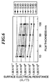
- Table 4 shows measurements results of the surface electrical resistance of thin films 11 prepared by sputtering in an argon-nitrogen mixture gas atmosphere using a Nb 2 O 5 -TiO 2 target (as in Example 1), with the thickness of the film being set to 10, 30, 50, and 100nm.
- the measurement results of Table 4 are shown in a graph of FIG. 6.
Landscapes
- Chemical & Material Sciences (AREA)
- Organic Chemistry (AREA)
- Engineering & Computer Science (AREA)
- Materials Engineering (AREA)
- Chemical Kinetics & Catalysis (AREA)
- Mechanical Engineering (AREA)
- Metallurgy (AREA)
- General Chemical & Material Sciences (AREA)
- Life Sciences & Earth Sciences (AREA)
- Geochemistry & Mineralogy (AREA)
- Physical Vapour Deposition (AREA)
- Surface Treatment Of Glass (AREA)
- Electrodes For Cathode-Ray Tubes (AREA)
- Cathode-Ray Tubes And Fluorescent Screens For Display (AREA)
- Cold Cathode And The Manufacture (AREA)
Abstract
A method of manufacturing a substrate for
displays is provided, which can easily control the
surface electrical resistance of the anti-electrification
film (11) formed on a surface of the
substrate (10), and a substrate for displays manufactured by
the same method. The film is formed by preparing a
target from a metal oxide, and forming a thin film of a
metal oxynitride on a surface of the substrate by
sputtering using the target in an atmosphere of a
mixture gas of an inert gas and nitrogen, a mixing ratio
of the inert gas and nitrogen in the atmosphere being
adjusted such that the thin film has a desired surface
electrical resistance.
Description
- The present invention relates to a method of manufacturing a substrate for displays and a substrate for displays manufactured by the same method, and more particularly, to a method of manufacturing a substrate for displays, which has a film formed thereon to prevent electrification of the substrate surface, and a substrate for displays manufactured by the same method.
- Conventional substrates for displays for use in field emission displays (FED) including surface-conduction electron-emitter devices (SED), and plasma display panels (PDP) had the disadvantage that the substrate surface is prone to electrification attributable to the driving method of the FED or PDP, i.e., due to application of a high electric field between the substrates for generation of light or due to exposure of the surface of the substrate to plasma. The electrification can cause generation of a spark, leading to a shortened service life of a display element. The electrification of the substrate surface depends on the surface electrical resistance of the substrate.
- To prevent the shortening of the life of the display element caused by electrification of the substrate surface, it has been proposed to form, on a surface of the substrate, a thin film of a metal oxynitride having a surface electrical resistance controlled to a desired value suitable for anti-electrification. The formation of the thin film of the metal oxynitride on the surface of the substrate is performed by sputtering using a metal target in a mixture gas atmosphere of oxygen and nitrogen. The surface electrical resistance of the thin film is controlled to a desired value by changing the mixing ratio of oxygen and nitrogen in the mixture gas atmosphere.
- According to the conventional anti-electrification method, however, it was difficult to control the surface electrical resistance to a desired value because when the ratio of oxygen and nitrogen in the mixture gas atmosphere is changed during sputtering using the metal target, the surface electrical resistance of the thin film to be formed on the surface of the substrate changes drastically even with a small change in the mixing ratio of oxygen and nitrogen.
- It is therefore an object of the present invention to provide a method of manufacturing a substrate for displays, which can easily control the surface electrical resistance of the anti-electrification film formed on a surface of the substrate, and a substrate for displays manufactured by the same method.
- To attain the above object, the present invention provides a method of manufacturing a substrate for displays, comprising the steps of preparing a target from a metal oxide, and forming a thin film of a metal oxynitride on a surface of the substrate by sputtering using the target in an atmosphere of a mixture gas of an inert gas and nitrogen, a mixing ratio of the inert gas and nitrogen in the atmosphere being adjusted such that the thin film has a desired surface electrical resistance.
- According to the method of the present invention, it is possible to easily control the value of the surface electrical resistance of the anti-electrification thin film formed on the surface of the substrate to a desired value.
- Preferably, the inert gas is contained in the atmosphere in an amount of 5 to 95 volume %.
- As a result, it is possible to form an anti-electrification thin film of metal oxynitride on the surface of the substrate in a reliable and a highly reproducible manner, thereby making it possible to positively control the value of the surface electrical resistance of the thin film to a desired value.
- Preferably, the desired surface electrical resistance is 1.0 x 10⁸ to 1.0 x 10² Ω/□.
- As a result, electric charges of the surface of the substrate can be dissipated, thereby making it possible to suppress the shortening of the life of the display element due to electrification of the substrate surface, that is, the element can fully withstand practical use.
- In a preferred form of the present invention, the target is formed of at least two kinds of metal oxides.
- As a result, it is possible to control the surface electrical resistance value of the thin film to a desired value in a more reliable manner.
- Preferably, one kind of the two kinds of metal oxides is an oxide of an element selected from the group consisting of titanium and zirconium.
- Preferably, the other kind of the two kinds of metal oxides is an oxide of an element selected from the group consisting of niobium, vanadium, tantalum, yttrium, and tungsten.
- Preferably, one kind of the two kinds of metal oxides is contained in the target in an amount of 70 to 99.5 weight %.
- Still preferably, the other kind of the two kinds of metal oxides is contained in the target in an amount of 0.5 to 30 weight %.
- As a result, it is possible to control the surface electrical resistance of the thin film in a more reliable manner.
- In another preferred form of the present invention, the method of manufacturing a substrate for displays further comprises the step of forming at least one anti-movable ion thermodiffusion film stacked on the thin film formed on the surface of the substrate.
- As a result, it is possible to prevent electrification of the substrate surface, as well as prevent abnormal operation of the display element due to thermodiffusion of movable ions.
- Preferably, the anti-movable ion thermodiffusion film is formed of a compound selected from the group consisting of an oxide of silicon, an oxynitride of silicon, or a nitride of silicon.
- As a result, it is possible to positively prevent abnormal operation of the display element due to thermodiffusion of movable ions.
- Preferably, the anti-movable ion thermodiffusion film has a total film thickness of 20 to 1000nm.
- As a result, it is possible to effectively prevent abnormal operation of the display element due to thermodiffusion of movable ions.
- Further, the present invention provides a substrate for displays manufactured by preparing a target from a metal oxide, and forming a thin film of a metal oxynitride on a surface of the substrate by sputtering using the target in an atmosphere of a mixture gas of an inert gas and nitrogen, a mixing ratio of said inert gas and nitrogen in said atmosphere being adjusted such that said thin film has a desired surface electrical resistance.
- According to the substrate for displays of the present invention, no electrification of the substrate surface can occur, making it possible to obtain a substrate for displays at a low cost without shortening of the life of the display element.
- The above and other objects, features and advantages of the invention will become more apparent from the following detailed description taken in conjunction with the accompanying drawings.
-
- FIG. 1 is a sectional view of a flat-type surface-conduction electron-emitter device with a substrate for a display according to an embodiment of the present invention;
- FIG. 2 is a sectional view of a
thin film 11 appearing in FIG. 1; - FIG. 3 is a graph showing the surface electrical
resistance of the
thin film 11 in Example 1; - FIG. 4 is a graph showing the surface electrical
resistance of the
thin film 11 in Comparative Example 1; - FIG. 5 is a graph showing the surface electrical
resistance of the
thin film 11 in Comparative Example 2; and - FIG. 6 is a graph showing the surface electrical
resistance of a
thin film 11 identical with thethin film 11 in Example 1 but with different film thickness values. -
- The present invention will now be described in detail with reference to the drawings showing a preferred embodiment thereof.
- To attain the object, the present inventors conducted extensive studies on a method of manufacturing a substrate for displays, which includes forming a thin film of a metal oxynitride having a desired surface electrical resistance on a surface of the substrate by sputtering using a target in a gas atmosphere containing nitrogen. As a result, the inventors reached a finding that if the target is formed of a metal oxide, the gas atmosphere is formed of a mixture of an inert gas and nitrogen, and the mixing ratio of the inert gas and oxygen of the gas atmosphere is adjusted such that the thin film has a desired surface electrical resistance, the change of the surface electrical resistance of the anti-electrification thin film becomes moderate relative to the change in the mixing ratio of the inert gas and nitrogen, thus making it possible to easily control the surface electrical resistance of the thin film to a desired value
- Further, it was found that preferably, if the content of the inert gas in the gas atmosphere is 5 to 95 volume %, it is possible to form the thin film of a metal oxynitride on the surface of the substrate in a reliable manner.
- Further, the present inventors also found that if the target is formed of at least two kinds of metal oxides, one of which is a metal oxide of either titanium or zirconium, and the other is a metal oxide of one of niobium, vanadium, tantalum, yttrium, and tungsten, and if the content of the former metal oxide is 70 to 99.5 weight %, and the content of the latter metal oxide is 0.5 to 30 weight %, then it is possible to control the value of the surface electrical resistance to a desired value in a more reliable manner.
- In particular, if the thin film is formed on the surface of the substrate by sputtering using a titanium oxide-based target containing 0.5 to 30 weight % of niobium in an atmosphere of an argon and nitrogen mixture gas, it is possible to control the value of the surface electrical resistance in an especially reliable manner. In this case, if the niobium oxide content is less than 0.5 weight %, a stable electric discharge cannot be conducted during sputtering. On the other hand, even if the niobium oxide content is above 30 weight %, the electric conductivity of the target does not change significantly.
- The present invention is based upon the above findings.
- The structure of a flat-type surface-conduction electron-emitter device (field emission element) with a substrate for a display according to an embodiment of the present invention will now be described in detail with reference to FIG. 1. FIG. 1 is a sectional view of the field emission element.
- In FIG. 1,
numeral 10 designates a glass substrate which has an element-formed surface on which athin film 11 is formed by sputtering, to prevent electrification of the surface of theglass substrate 10. Thesubstrate 10 is formed of soda-lime glass, and has a thickness of, for example, 3mm. Thethin film 11 has a thickness of, for example, 10nm. - A pair of
element electrodes thin film 11. Theelement electrodes - The shape of the
element electrodes - A
conductive film 14 is formed between theelement electrodes conductive film 14 and theelement electrodes electron emitting part 15 having a higher electrical resistance than theconductive film 14 is formed in a part of theconductive film 14, by an electroforming method. - The
electron emitting part 15 and its neighboring area are coated with athin film 16. Thethin film 16, which is formed of carbon or a carbon compound, is formed after the formation of theelectron emitting part 15, by an electric activation method. - The
thin film 11 is formed of at least two kinds of metal oxynitrides, one of which is a metal oxynitride of either titanium or zirconium (TiON, ZrON), and the other is a metal oxynitride of one of niobium, vanadium, tantalum, yttrium, and tungsten (NbON, VaON, TaON, YON, or WON). "ON" in the terms TION and such does not mean a stoichiometric representation, but simply implies that both of oxygen and nitrogen are contained. The same applies to the term "ON" mentioned hereinafter. - The formation of the
thin film 11 on the surface of thesubstrate 10 by sputtering is carried out using a metal oxide target in a gas atmosphere of a mixture of an inert gas and nitrogen, while the mixing ratio of the inert gas and nitrogen in the gas atmosphere is adjusted such that thethin film 14 exhibits a desired surface electrical resistance. - It is preferable that the surface electrical resistance of the
thin film 11 is in a range of 1.0 x10⁸ to 1.0 x10¹² Ω/□. This range allows electric charges of the substrate surface to be dissipated, so that the shortening of the life of the display element due to the electrification of the substrate surface can be suppressed. That is, the display element can fully withstand practical use. - It is preferable that the surface electrical resistance of the metal oxide target is 10 Ω/□ or less. This enables the formation of the
thin film 11 to be controlled in a reliable manner. - Further, as shown in FIG. 2, the
thin film 11 may be formed by stacking at least one alkali-ion passivation film 11b (anti-movable ion thermodiffusion film) containing a compound selected from the group consisting of SiO2 an oxynitride of silicon (SiON), and a nitride of silicon, on the above described thin film ha formed of at least two kinds of the metal oxynitrides. This prevents not only electrification of the surface of the substrate but also abnormal operation of the display element due to alkali-ion thermodiffusion. - It is preferable that the total film thickness of the at least one alkali-
ion passivation film 11b is 20 to 1000nm. If the total film thickness is less than 20nm, it is not possible to prevent abnormal operation of the display element due to alkali-ion thermodiffusion, while if the total film thickness is more than 1000nm, the effect of preventing alkali-ion thermodiffusion is not significantly improved. - In the
thin film 11, the stacking order of the at least twolayers - The following experiments were conducted in order to confirm the above described findings of the present invention.
- First,
substrates 10 constructed as above were prepared from a soda-lime glass material having a thickness of 3mm (consisting essentially of 72 weight % of SiO2, 13 weight % of Na2O, 8 weight % of CaO, 4 weight % of MgO, 1.8 weight % of Al2O3 and 0.9 weight % of K2O). Then,thin films 11 were formed on surfaces of thesubstrates 10 by sputtering, using targets and mixture gas atmospheres shown in Table 1.EXAMPLE ACCORDING TO PRESENT INVENTION COMPARATIVE EXAMPLES 1 1 2 TARGET Nb2O5-TiO2 Nb2O5-TiO2 Ti GAS FLOW RATE A (SCCM) GAS FLOW RATE B (SCCM) GAS FLOW RATE RATIO A/(A+B) SURFACE ELECTRICAL RESISTANCE (Ω/□) A:Ar, B:N2 SURFACE ELECTRICAL RESISTANCE (Ω/□) A:Ar, B:O2 SURFACE ELECTRICAL RESISTANCE (Ω/□) A:N2, B:O2 0 50 0.00 3.80 × 10⁷ 6.00 × 10¹⁶ 6.30 × 10¹⁶ 2.5 47.5 0.05 1.49 × 10⁹ 5.50 × 10¹⁶ 5.85 × 10¹⁶ 10 40 0.20 2.94 × 10⁹ 5.00 × 10¹⁶ 5.40 × 10¹⁶ 20 30 0.40 1.66 × 10¹⁰ 2.00 × 10¹⁶ 3.00 × 10¹⁶ 25 25 0.50 7.65 × 10⁹ 1.00 × 10¹⁶ 2.30 × 10¹⁶ 30 20 0.60 1.00 × 10⁹ 9.00 × 10¹⁵ 2.00 × 10¹⁶ 40 10 0.80 5.00 × 10⁸ 6.88 × 10¹⁵ 6.00 × 10¹⁵ 47.5 2.5 0.95 2.54 × 10⁸ 3.44 × 10¹⁵ 3.00 × 10¹⁵ 50 0 1.00 8.00 × 10⁶ 8.00 × 10⁶ 2.00 × 10⁵ - Table 1 contains Example 1 in which sputtering was conducted using a Nb2O5-TiO2 target (the Nb2O5 content is 2.5 weight %) in an argon-nitrogen mixture gas atmosphere, Comparative Example 1 in which sputtering was conducted using a Nb2O5-TiO2 target in an argon-oxygen mixture gas atmosphere, and Comparative Example 2 in which sputtering was conducted using a Ti target in a nitrogen-oxygen mixture gas atmosphere. In each example, the flow rate ratio (A/(A+B)) of a first gas component flow rate A was varied from 0 to 100% (that is, (B/(A+B)) of the other gas component flow rate B was varied from 100 to 0 %).
- The method of preparing one of the above targets will be explained with reference to the Nb2O5-TiO2 target as an example. The other targets were prepared in similar manners.
- First, a fine powder of 97.5 weight % of titanium oxide (TiO2) and a fine powder of 2.5 weight % niobium oxide (Nb2O5) were thoroughly mixed. Then, 2 weight % of an organic binder was added to the TiO2 and Nb2O5 mixture, followed by agitating in a vibrating mill for 2 hours. Then, water was added to the resulting mixture to granulate the same, followed by conducting cold hydrostatic molding under a pressure of 3.5 ton/cm2. The resulting molded piece was then heated to 400°C to degrease the same, followed by presintering in an oxygen atmosphere at 1400°C for 5 hours. Further, the presintered piece was charged into a crucible, which was then sealed. The presintered piece in the crucible was subjected to hot isotropic press working in an argon atmosphere containing a slight amount of oxygen gas, at 1350 °C and under a pressure of 50MPa, thereby preparing a Nb2O5-TiO2 sintered body target.
- The obtained Nb2O5-TiO2 target showed a relative density of 96% or more as a result of measurement according to Archimedes Method, and showed a surface electrical resistance of approximately 2 Ω/□ as a result of measurement according to the four terminal method.
- Next, the method of forming the
thin film 11 of Example 1 by sputtering will be described. - The Nb2O5-TiO2 target prepared as above was set in an in-line type sputtering apparatus comprised of a preliminary evacuation chamber and a sputter chamber. The sputter chamber was evacuated to 5.0 x10⁻⁴ Pa or less by a rotary pump and a cryopump. Then, a
substrate 10, which was cleaned in advance and had a thickness of 3mm, was inserted into the preliminary evacuation chamber, followed by evacuating the chamber to 0.3 Pa or less. Then, thesubstrate 10 was moved into the sputter chamber, and an argon gas was introduced into the chamber at a rate of 50cm3/min. (standard cubic centimeters per minute) (hereinafter referred to as "SCCM"), to adjust the pressure to 0.3 Pa. Then, electric power was supplied from a direct current source to a cathode holding the target to cause an electric discharge of the target, while thesubstrate 10 was passed over the target, to form athin film 11 of a mixture of titanium oxide and niobium oxide having a thickness of 10nm on a surface of thesubstrate 10. The surface electrical resistance of thethin film 11 was 8.00 x10⁶ Ω/□. - Further, a
thin film 11 of a mixture of titanium oxynitride and niobium oxynitride having a thickness of 10nm was formed in the same manner as above, by introducing argon gas at 47.5 SCCM and nitrogen gas at 2.5 SCCM into the sputter chamber to adjust the pressure to 0.3 Pa. The surface electrical resistance of thisthin film 11 was 2.54 x 10⁸ Ω/□. - In the same manner,
thin films 11 having a thickness of 10nm were formed on surfaces of thesubstrates 10 as Example 1 and Comparative Example 1, according to various gas flow rate ratios indicated in Table 1, and the surface electrical resistance of each example was measured (however, for Comparative Example 1, argon gas and oxygen gas were introduced as components of the atmosphere gas, according to gas flow rate ratios indicated in Table 1). - Next, the method of forming the
thin film 11 of Comparative Example 2 by sputtering will be described. - A
thin film 11 was formed by using a Ti target and an in-line type sputtering apparatus comprised of a preliminary evacuation chamber and a sputter chamber. More specifically, a metal titanium target was set in the sputter chamber, and then the sputter chamber was evacuated to 5.0 x 10⁻⁴ Pa or less by a rotary pump and a cryopump. Then, asubstrate 10 with a thickness of 3mm, which was cleaned in advance, was inserted into the preliminary evacuation chamber and the chamber was evacuated to 0.3 Pa or less. Next, thesubstrate 10 was moved into the sputter chamber, into which a nitrogen gas was introduced at a rate of 50 SCCM to adjust the pressure to 0.3 Pa. Then, electric power was supplied from a direct current source to a cathode holding the Ti target to cause an electric discharge of the Ti target, while thesubstrate 10 was passed over the target, to form athin film 11 of titanium oxynitride having a thickness of 10nm on a surface of thesubstrate 10. The surface electrical resistance of thisthin film 11 was 2.0 x 10⁵ Ω/□. - Further, a
thin film 11 of titanium oxynitride having a thickness of 10nm was formed in the same manner as above, by introducing nitrogen gas at 47.5 SCCM and oxygen gas at 2.5 SCCM into the sputter chamber to adjust the pressure to 0.3 Pa. The surface electrical resistance of thisthin film 11 was 3.0 x 10¹⁵ Ω/□. - In the sante manner,
thin films 11 having a thickness of 10nm were formed on surfaces ofsubstrates 10, according to gas flow rate ratios indicated in Table 1. The surface electrical resistance of each example was measured. - The measurement results of Example 1 and Comparative Examples 1 and 2 are shown in Table 1. Further, the measurement results of Example 1 and Comparative Examples 1 and 2 in Table 1 are shown in graphs of FIG. 3, FIG. 4 and FIG. 5, respectively.
- According to FIG. 3, when sputtering is conducted in an argon-nitrogen mixture gas atmosphere using a Nb2O5-TiO2 target as in Example 1, insofar as the gas flow rate ratio (A/(A+B)) varies from 5 to 95 volume % (in the case of nitrogen gas , insofar as the gas flow rate ratio (B/(A+B)) varies from 95 to 5 volume %), the surface electrical resistance of the
thin film 11 falls steadily within 1.0 x 10⁸ to 1.0 x 10¹² Ω/□. However, when the gas flow ratio rate is less than 5 volume % or above 95 volume %, the surface electrical resistance of thethin film 11 falls below 1.0x 10⁸ Ω/□. - Thus, it can be seen from FIG. 3 that when the gas flow rate ratio (A/(A+B)) is within the range of 5 to 95 volume %, it is possible to obtain a
thin film 11 having a surface electrical resistance of 1.0 x 10⁸ to 1.0 x 10¹² Ω/□. - Further, it can be seen from FIG. 4 and FIG. 5 that when sputtering is conducted in an argon-oxygen mixture gas atmosphere using a Nb2O5-TiO2 target, as in Comparative Example 1, and when sputtering is conducted in a nitrogen-oxygen mixture gas atmosphere using a Ti target, as in Comparative Example 2, it is not possible to keep the surface electrical resistance within 1.0 x 10⁸ to 1.0 x 10¹² Ω/□, irrespective of the gas flow rate ratio.
- According to the above experiments, while a metal, oxygen, and nitrogen are needed to generate a metal oxynitride, Example 1, in which the metal and oxygen are supplied from the target and nitrogen is supplied from the mixture gas atmosphere, is able to obtain good results of the value of surface electrical resistance of the
thin film 11, whereas, Comparative Example 1, in which the metal and oxygen are supplied from the target, but nitrogen is not supplied from the mixture gas atmosphere, and Comparative Example 2, in which the metal is supplied from the target, but neither nitrogen nor oxygen is supplied from the mixture gas atmosphere, are not able to obtain satisfactory surface electrical resistance values. - Further, it can be understood that in Example 1 according to the present invention, the rate of change of the surface electrical resistance of the
thin film 11 is gentle compared with the rate of change of the gas flow rate ratio between argon and oxygen in the mixture gas atmosphere. Therefore, a desired surface resistance value of thethin film 11 can be obtained simply by adjusting the flow rate ratio (mixing ratio of argon and oxygen) as a parameter. - On the other hand, in Comparative Example 1 and Comparative Example 2, as the gas flow rate ratio (A/(A+B)) was changed from 95 volume % to 100 volume %, the surface electrical resistance of the
thin film 11 changed drastically, which made it impossible to steadily keep the surface electrical resistance of the thin film within the range of 1.0 x 10⁸ to 1.0 x 10¹² Ω/□ in a reliable manner (FIG. 4 and FIG. 5). - Table 2 shows measurement results of the surface electrical resistance of
thin films 11 prepared according to Example 1 and Comparative Example 2. In Example 1, tenthin films 11, each having a thickness of 10nm, were formed by sputtering using a Nb2O5-TiO2 target in an argon-oxygen mixture gas atmosphere with the gas flow rate ratio at 95 volume %. In Comparative Example 2, tenthin films 11, each having a thickness of 10nm, were formed by sputtering using a Ti target in an oxygen-nitrogen mixture gas atmosphere with the gas flow rate ratio at 95 volume %.EXAMPLE ACCORDING TO PRESENT INVENTION COMPARATIVE EXAMPLE 1 2 TARGET Nb2O5-TiO2 Ti GAS ATMOSPHERE A:Ar, B:N2 A:O2, B:N2 SURFACE ELECTRICAL RESISTANCE (Ω/□) 7.65 × 10⁹ 5.82 × 10¹⁴ 1.00 × 10⁹ 1.16 × 10¹⁵ 3.00 × 10⁹ 1.25 × 10⁶ 5.00 × 10⁹ 6.52 × 10¹¹ 2.90 × 10⁹ 6.52 × 10⁵ 2.30 × 10⁹ 5.82 × 10⁴ 2.10 × 10⁹ 5.82 × 10¹⁴ 5.00 × 10⁹ 1.16 × 10¹⁵ 1.70 × 10⁹ 1.75 × 10¹⁵ 1.90 × 10⁹ 2.33 × 10¹⁵ AVERAGE (Ω/□) 3.25 × 10⁹ 7.56 × 10¹⁴ STANDARD DEVIATION (Ω/□) 2.03 × 10⁹ 8.25 × 10¹⁴ - It can be seen from Table 2 that while the
thin films 11 according to Example 1 show substantially constant values of the surface electrical resistance, thethin films 11 according to Comparative Example 2, of which the nitrogen gas atmosphere contains just 5 volume % of oxygen gas, show drastic changes in surface electrical resistance between them. - Next, as Examples 2 to 5, a V2O5-TiO2 target (containing 0.5 weight % of V2O5), a WO3-TiO2 target (containing 5 weight % of WO3), a Y2O3-TiO2 target (containing 10 weight % of Y2O3), and a Ta2O5-TiO2 target (containing 8 weight % of Ta2O5) were used, respectively. These targets were each subjected to sputtering in an argon-nitrogen mixture gas atmosphere while altering the gas flow rate ratio between 0 to 100%, to thereby form
thin films 11 onsubstrates 10. The surface electrical resistance of each of thethin films 11 was measured and the results are shown in Table 3.
- It can be seen from Table 3 that in all Examples 2 to 5, as the gas flow rate ratio varies from 5 to 95 volume % (in the case of the nitrogen gas, as the gas flow rate ratio varies from 95 to 5 volume %), the surface electrical resistance of the
thin film 11 is steadily kept within the range of 1.0 x 10⁸ to 1.0 x 10¹² Ω/□ in a reliable manner. On the other hand, when the gas flow rate ratio is below 5 volume % or above 95 volume %, the surface electrical resistance falls below 1.0 x 10⁸ Ω/□. - In Examples 1 to 5 in Tables 1 and 3, when the metal oxides constituting components other than the main component of the target (Nb2O5, V2O5, WO3, Y2O3, and Ta2O5) are contained in a range of 0.5 to 10 weight %, in other words, when the metal oxide (TiO2) which constitutes the main component of the target is contained in a range of 90 to 99.5 weight %, the value of the surface electrical resistance of the
thin film 11 is controlled to a desired range. - Table 4 shows measurements results of the surface electrical resistance of
thin films 11 prepared by sputtering in an argon-nitrogen mixture gas atmosphere using a Nb2O5-TiO2 target (as in Example 1), with the thickness of the film being set to 10, 30, 50, and 100nm. The measurement results of Table 4 are shown in a graph of FIG. 6.GAS FLOW RATE RATIO A/(A+B) SURFACE ELECTRICAL RESISTANCE (Ω/□) FILM THICKNESS 10nm FILM THICKNESS 30nm FILM THICKNESS 50nm FILM THICKNESS 100nm 0.00 3.80 × 10⁷ 1.27 × 10⁷ 7.60 × 10⁶ 3.80 × 10⁶ 0.05 1.49 × 10⁹ 4.97 × 10⁸ 2.98 × 10⁸ 1.49 × 10⁸ 0.20 2.94 × 10⁹ 9.81 × 10⁸ 5.88 × 10⁸ 2.94 × 10⁸ 0.40 1.66 × 10¹⁰ 5.53 × 10⁹ 3.32 × 10⁹ 1.66 × 10⁹ 0.50 7.65 × 10⁹ 2.55 × 10⁹ 1.53 × 10⁹ 7.65 × 10⁸ 0.60 1.00 × 10⁹ 3.33 × 10⁸ 2.00 × 10⁸ 1.00 × 10⁸ 0.80 5.00 × 10⁸ 1.67 × 10⁸ 1.00 × 10⁸ 5.00 × 10⁷ 0.95 2.54 × 10⁸ 8.47 × 10⁷ 5.08 × 10⁷ 2.54 × 10⁷ 1.00 8.00 × 10⁶ 2.67 × 10⁶ 1.60 × 10⁶ 8.00 × 10⁵ - It can be seen from FIG. 6 that there is no significant change in the surface electrical resistance even when the thickness of the
thin film 11 increases, and that in examples being low in surface electrical resistance, the surface electrical resistance increases when the film thickness of thethin film 11 is reduced. Further, although there is no specific limit to the film thickness of thethin film 11, basically a thin film is preferable in terms of the manufacturing cost, and the film thickness may be adjusted appropriately to a desired thickness.
Claims (22)
- A method of manufacturing a substrate for displays, comprising the steps of:preparing a target from a metal oxide; andforming a thin film of a metal oxynitride on a surface of the substrate by sputtering using said target in an atmosphere of a mixture gas of an inert gas and nitrogen, a mixing ratio of said inert gas and nitrogen in said atmosphere being adjusted such that said thin film has a desired surface electrical resistance.
- A method as claimed in claim 1, wherein said inert gas is contained in said atmosphere in an amount of 5 to 95 volume %.
- A method as claimed in claim 1 or 2, wherein said desired surface electrical resistance is 1.0 x 10⁸ to 1.0 x 10¹² Ω/□.
- A method as claimed in any of claims 1 to 3, wherein said target is formed of at least two kinds of metal oxides.
- A method as claimed in claim 4, wherein one kind of said two kinds of metal oxides is an oxide of an element selected from the group consisting of titanium and zirconium.
- A method as claimed in claim 5, wherein the other kind of said two kinds of metal oxides is an oxide of an element selected from the group consisting of niobium, vanadium, tantalum, yttrium, and tungsten.
- A method as claimed in claim 5 or 6, wherein said one kind of said two kinds of metal oxides is contained in said target in an amount of 70 to 99.5 weight %.
- A method as claimed in claim 6 or 7, wherein the other kind of said two kinds of metal oxides is contained in said target in an amount of 0.5 to 30 weight %.
- A method as claimed in any of claims 1 to 8, further comprising the step of forming at least one anti-movable ion thermodiffusion film stacked on said thin film formed on the surface of said substrate.
- A method as claimed in claim 9, wherein said anti-movable ion thermodiffusion film is formed of a compound selected from the group consisting of an oxide of silicon, an oxynitride of silicon, or a nitride of silicon.
- A method as claimed in claim 9 or 10, wherein said anti-movable ion thermodiffusion film has a total film thickness of 20 to 1000nm.
- A substrate for displays manufactured by preparing a target from a metal oxide, and forming a thin film of a metal oxynitride on a surface of the substrate by sputtering using said target in an atmosphere of a mixture gas of an inert gas and nitrogen, a mixing ratio of said inert gas and nitrogen in said atmosphere being adjusted such that said thin film has a desired surface electrical resistance.
- A substrate for displays as claimed in claim 12, wherein said inert gas is contained in said atmosphere in an amount of 5 to 95 volume %.
- A substrate for displays as claimed in claim 12 or 13, wherein said desired surface electrical resistance is 1.0 x 10⁸ to 1.0 x 10¹² Ω/□.
- A substrate for displays as claimed in any of claims 12 to 14, wherein said target is formed of at least two kinds of metal oxides
- A substrate for displays as claimed in claim 15, wherein one kind of said two kinds of metal oxides is an oxide of an element selected from the group consisting of titanium and zirconium.
- A substrate for displays as claimed in claim 16, wherein the other kind of said two kinds of metal oxides is an oxide of an element selected from the group consisting of niobium, vanadium, tantalum, yttrium, and tungsten.
- A substrate for displays as claimed in claim 16 or 17, wherein said one kind of said two kinds of metal oxides is contained in said target in an amount of 70 to 99.5 weight %.
- A substrate for displays as claimed in claim 16 or 17, wherein the other kind of said two kinds of metal oxides is is contained in said target in an amount of 0.5 to 30 weight %.
- A substrate for displays as claimed in any of claims 11 to 19, further comprising at least one anti-movable ion thermodiffusion film stacked on said thin film formed on the surface of said substrate.
- A substrate for displays as claimed in claim 20, wherein said anti-movable ion thermodiffusion film is formed of a compound selected from the group consisting of an oxide of silicon, an oxynitride of silicon, or a nitride of silicon.
- A substrate for displays as claimed in claim 20 or 21, wherein said anti-movable ion thermodiffusion film has a total film thickness of 20 to 1000nm.
Applications Claiming Priority (2)
| Application Number | Priority Date | Filing Date | Title |
|---|---|---|---|
| JP20917899A JP2001032064A (en) | 1999-07-23 | 1999-07-23 | Production of substrate for display and substrate for display produced by the producing method |
| JP20917899 | 1999-07-23 |
Publications (1)
| Publication Number | Publication Date |
|---|---|
| EP1070766A1 true EP1070766A1 (en) | 2001-01-24 |
Family
ID=16568636
Family Applications (1)
| Application Number | Title | Priority Date | Filing Date |
|---|---|---|---|
| EP00402066A Withdrawn EP1070766A1 (en) | 1999-07-23 | 2000-07-20 | Substrate for displays and method for its manufacture |
Country Status (6)
| Country | Link |
|---|---|
| US (1) | US6362084B1 (en) |
| EP (1) | EP1070766A1 (en) |
| JP (1) | JP2001032064A (en) |
| KR (1) | KR20010049856A (en) |
| CN (1) | CN1282091A (en) |
| TW (1) | TW593713B (en) |
Families Citing this family (10)
| Publication number | Priority date | Publication date | Assignee | Title |
|---|---|---|---|---|
| JP4596444B2 (en) * | 2001-03-23 | 2010-12-08 | 大日本印刷株式会社 | Method for forming electrode pattern by offset printing |
| JP3682920B2 (en) * | 2001-10-30 | 2005-08-17 | 富士通株式会社 | Manufacturing method of semiconductor device |
| JP3840251B2 (en) * | 2004-03-10 | 2006-11-01 | キヤノン株式会社 | ELECTRON EMITTING ELEMENT, ELECTRON SOURCE, IMAGE DISPLAY DEVICE, INFORMATION DISPLAY REPRODUCING DEVICE USING THE IMAGE DISPLAY DEVICE, AND METHOD FOR MANUFACTURING THE SAME |
| US20080271988A1 (en) * | 2004-06-29 | 2008-11-06 | Yasuo Hosoda | Thin Film Forming Sputtering Target, Dielectric Thin Film, Optical Disc and Production Method Therefor |
| TWI344167B (en) | 2007-07-17 | 2011-06-21 | Chunghwa Picture Tubes Ltd | Electron-emitting device and fabricating method thereof |
| TWI424074B (en) * | 2009-03-27 | 2014-01-21 | Jx Nippon Mining & Metals Corp | Ti-Nb-based sintered body sputtering target, Ti-Nb-based oxide thin film, and method for producing the same |
| EP2738815B1 (en) | 2012-11-30 | 2016-02-10 | Samsung Electronics Co., Ltd | Semiconductor materials, transistors including the same, and electronic devices including transistors |
| JP6859837B2 (en) * | 2017-05-09 | 2021-04-14 | 三菱マテリアル株式会社 | Oxide sputtering target |
| KR102021066B1 (en) | 2019-05-15 | 2019-11-04 | (주)왕선사람들 | Pettitoes using germanium bean-sprouts and manufacturing method thereof |
| KR102180266B1 (en) | 2020-06-30 | 2020-11-18 | (주)왕선사람들 | Pettitoes using germanium bean-sprouts and manufacturing method thereof |
Citations (4)
| Publication number | Priority date | Publication date | Assignee | Title |
|---|---|---|---|---|
| US4954744A (en) * | 1988-05-26 | 1990-09-04 | Canon Kabushiki Kaisha | Electron-emitting device and electron-beam generator making use |
| JPH06346076A (en) * | 1993-06-03 | 1994-12-20 | Riken Corp | Sliding part |
| JPH08162001A (en) * | 1994-12-09 | 1996-06-21 | Canon Inc | Electron source substrate, electron source, image forming device and manufacture |
| EP0913367A1 (en) * | 1996-06-11 | 1999-05-06 | Asahi Glass Company Ltd. | Light-absorbing antireflective body and process for the production thereof |
Family Cites Families (4)
| Publication number | Priority date | Publication date | Assignee | Title |
|---|---|---|---|---|
| JPS61172754A (en) * | 1985-01-26 | 1986-08-04 | Kyocera Corp | Thermal head |
| US5557313A (en) * | 1992-11-12 | 1996-09-17 | Tdk Corporation | Wear-resistant protective film for thermal head and method of producing the same |
| JPH09283866A (en) * | 1996-04-10 | 1997-10-31 | Nippon Sheet Glass Co Ltd | Substrate with transparent conductive film |
| US6046758A (en) * | 1998-03-10 | 2000-04-04 | Diamonex, Incorporated | Highly wear-resistant thermal print heads with silicon-doped diamond-like carbon protective coatings |
-
1999
- 1999-07-23 JP JP20917899A patent/JP2001032064A/en active Pending
-
2000
- 2000-07-17 TW TW089114265A patent/TW593713B/en not_active IP Right Cessation
- 2000-07-20 EP EP00402066A patent/EP1070766A1/en not_active Withdrawn
- 2000-07-20 US US09/619,329 patent/US6362084B1/en not_active Expired - Fee Related
- 2000-07-22 KR KR1020000042256A patent/KR20010049856A/en not_active Application Discontinuation
- 2000-07-24 CN CN00121464.0A patent/CN1282091A/en active Pending
Patent Citations (4)
| Publication number | Priority date | Publication date | Assignee | Title |
|---|---|---|---|---|
| US4954744A (en) * | 1988-05-26 | 1990-09-04 | Canon Kabushiki Kaisha | Electron-emitting device and electron-beam generator making use |
| JPH06346076A (en) * | 1993-06-03 | 1994-12-20 | Riken Corp | Sliding part |
| JPH08162001A (en) * | 1994-12-09 | 1996-06-21 | Canon Inc | Electron source substrate, electron source, image forming device and manufacture |
| EP0913367A1 (en) * | 1996-06-11 | 1999-05-06 | Asahi Glass Company Ltd. | Light-absorbing antireflective body and process for the production thereof |
Non-Patent Citations (3)
| Title |
|---|
| NGUYEN L Q ET AL: "A novel lithium conductor prepared by unbalanced magnetron r.f. sputtering", THIN SOLID FILMS,CH,ELSEVIER-SEQUOIA S.A. LAUSANNE, vol. 293, no. 1-2, 30 January 1997 (1997-01-30), pages 175 - 178, XP004080853, ISSN: 0040-6090 * |
| PATENT ABSTRACTS OF JAPAN vol. 1995, no. 03 28 April 1995 (1995-04-28) * |
| PATENT ABSTRACTS OF JAPAN vol. 1996, no. 10 31 October 1996 (1996-10-31) * |
Also Published As
| Publication number | Publication date |
|---|---|
| US6362084B1 (en) | 2002-03-26 |
| JP2001032064A (en) | 2001-02-06 |
| TW593713B (en) | 2004-06-21 |
| CN1282091A (en) | 2001-01-31 |
| KR20010049856A (en) | 2001-06-15 |
Similar Documents
| Publication | Publication Date | Title |
|---|---|---|
| EP0735152B1 (en) | Molybdenum-tungsten material for wiring, molybdenum-tungsten target for wiring, process for producing the same, and molybdenum-tungsten wiring thin film | |
| US7153453B2 (en) | Oxide sintered body, sputtering target, transparent conductive thin film and manufacturing method therefor | |
| JP4926977B2 (en) | Gallium oxide-zinc oxide sintered sputtering target | |
| US20160070033A1 (en) | Light-absorbing layer and layer system containing the layer, method for producing the layer system and a sputter target suited therefor | |
| KR100847410B1 (en) | Antistatic film, spacer using it and picture display unit | |
| EP1897969A1 (en) | Gallium oxide-zinc oxide sputtering target, method for forming transparent conductive film, and transparent conductive film | |
| US6362084B1 (en) | Method of manufacturing a substrate for displays and a substrate for displays manufactured by same | |
| EP3061739B1 (en) | Silicon nitride substrate and silicon nitride circuit board using same | |
| JP2004091265A (en) | Oxide sintered compact | |
| US7431808B2 (en) | Sputter target based on titanium dioxide | |
| KR20080015892A (en) | Gallium oxide-zinc oxide sputtering target, method of forming transparent conductive film and transparent conductive film | |
| KR20100135957A (en) | Molybdenum-niobium alloys, sputtering targets containing such alloys, methods of making such targets, thin films prepared therefrom and uses thereof | |
| TWI753835B (en) | Dielectrics for electrostatic chucks | |
| JP2004217990A (en) | Sputtering target, and production method therefor | |
| JP2004006221A (en) | Transparent conductive thin film, manufacturing method thereof, sintering body target for manufacturing the same, organic electroluminescent element and its manufacturing process | |
| JPH1088332A (en) | Sputtering target, transparent conductive coating and its production | |
| JPH07196365A (en) | Sintered ito, ito clear conductive layer and formation thereof | |
| JPH09176850A (en) | Sputtering device and production of dielectric film | |
| EP1004687B1 (en) | SUBSTRATE COATED WITH A TRANSPARENT CONDUCTIVE FILM and SPUTTERING TARGET FOR THE DEPOSITION OF SAID FILM | |
| KR0141194B1 (en) | Fabrication method of target for sputturing | |
| JP3472993B2 (en) | Sputtering target for forming indium tin oxide film and method for producing the same | |
| WO2008051846A1 (en) | Mixed chromium oxide-chromium metal sputtering target | |
| JP2005235751A (en) | Antistatic film, spacer using it, and image display device | |
| EP1380665B1 (en) | Method of using hydrogen and oxygen gas in sputter deposition of aluminum-containing films and aluminum-containing films derived therefrom | |
| JPH03232959A (en) | Production of thin film |
Legal Events
| Date | Code | Title | Description |
|---|---|---|---|
| PUAI | Public reference made under article 153(3) epc to a published international application that has entered the european phase |
Free format text: ORIGINAL CODE: 0009012 |
|
| AK | Designated contracting states |
Kind code of ref document: A1 Designated state(s): DE FR GB NL |
|
| AX | Request for extension of the european patent |
Free format text: AL;LT;LV;MK;RO;SI |
|
| 17P | Request for examination filed |
Effective date: 20010724 |
|
| AKX | Designation fees paid |
Free format text: DE FR GB NL |
|
| STAA | Information on the status of an ep patent application or granted ep patent |
Free format text: STATUS: THE APPLICATION IS DEEMED TO BE WITHDRAWN |
|
| 18D | Application deemed to be withdrawn |
Effective date: 20030201 |