EP1070675A2 - Winding machine for forming large-diameter reels of web material with mandrel insertion means - Google Patents
Winding machine for forming large-diameter reels of web material with mandrel insertion means Download PDFInfo
- Publication number
- EP1070675A2 EP1070675A2 EP00120695A EP00120695A EP1070675A2 EP 1070675 A2 EP1070675 A2 EP 1070675A2 EP 00120695 A EP00120695 A EP 00120695A EP 00120695 A EP00120695 A EP 00120695A EP 1070675 A2 EP1070675 A2 EP 1070675A2
- Authority
- EP
- European Patent Office
- Prior art keywords
- winding
- mandrel
- rolls
- rewinding machine
- reel
- Prior art date
- Legal status (The legal status is an assumption and is not a legal conclusion. Google has not performed a legal analysis and makes no representation as to the accuracy of the status listed.)
- Granted
Links
Images


Classifications
-
- B—PERFORMING OPERATIONS; TRANSPORTING
- B65—CONVEYING; PACKING; STORING; HANDLING THIN OR FILAMENTARY MATERIAL
- B65H—HANDLING THIN OR FILAMENTARY MATERIAL, e.g. SHEETS, WEBS, CABLES
- B65H19/00—Changing the web roll
- B65H19/22—Changing the web roll in winding mechanisms or in connection with winding operations
- B65H19/30—Lifting, transporting, or removing the web roll; Inserting core
- B65H19/305—Inserting core
-
- B—PERFORMING OPERATIONS; TRANSPORTING
- B65—CONVEYING; PACKING; STORING; HANDLING THIN OR FILAMENTARY MATERIAL
- B65H—HANDLING THIN OR FILAMENTARY MATERIAL, e.g. SHEETS, WEBS, CABLES
- B65H18/00—Winding webs
- B65H18/08—Web-winding mechanisms
- B65H18/14—Mechanisms in which power is applied to web roll, e.g. to effect continuous advancement of web
- B65H18/20—Mechanisms in which power is applied to web roll, e.g. to effect continuous advancement of web the web roll being supported on two parallel rollers at least one of which is driven
-
- B—PERFORMING OPERATIONS; TRANSPORTING
- B65—CONVEYING; PACKING; STORING; HANDLING THIN OR FILAMENTARY MATERIAL
- B65H—HANDLING THIN OR FILAMENTARY MATERIAL, e.g. SHEETS, WEBS, CABLES
- B65H2301/00—Handling processes for sheets or webs
- B65H2301/40—Type of handling process
- B65H2301/41—Winding, unwinding
- B65H2301/413—Supporting web roll
- B65H2301/4134—Both ends type arrangement
- B65H2301/41346—Both ends type arrangement separate elements engaging each end of the roll (e.g. chuck)
-
- B—PERFORMING OPERATIONS; TRANSPORTING
- B65—CONVEYING; PACKING; STORING; HANDLING THIN OR FILAMENTARY MATERIAL
- B65H—HANDLING THIN OR FILAMENTARY MATERIAL, e.g. SHEETS, WEBS, CABLES
- B65H2301/00—Handling processes for sheets or webs
- B65H2301/40—Type of handling process
- B65H2301/41—Winding, unwinding
- B65H2301/417—Handling or changing web rolls
- B65H2301/4171—Handling web roll
- B65H2301/41745—Handling web roll by axial movement of roll
-
- B—PERFORMING OPERATIONS; TRANSPORTING
- B65—CONVEYING; PACKING; STORING; HANDLING THIN OR FILAMENTARY MATERIAL
- B65H—HANDLING THIN OR FILAMENTARY MATERIAL, e.g. SHEETS, WEBS, CABLES
- B65H2301/00—Handling processes for sheets or webs
- B65H2301/40—Type of handling process
- B65H2301/41—Winding, unwinding
- B65H2301/417—Handling or changing web rolls
- B65H2301/418—Changing web roll
- B65H2301/4181—Core or mandrel supply
- B65H2301/41818—Core or mandrel supply mandrels circulating (cycling) in machine or system
-
- B—PERFORMING OPERATIONS; TRANSPORTING
- B65—CONVEYING; PACKING; STORING; HANDLING THIN OR FILAMENTARY MATERIAL
- B65H—HANDLING THIN OR FILAMENTARY MATERIAL, e.g. SHEETS, WEBS, CABLES
- B65H2301/00—Handling processes for sheets or webs
- B65H2301/40—Type of handling process
- B65H2301/41—Winding, unwinding
- B65H2301/417—Handling or changing web rolls
- B65H2301/418—Changing web roll
- B65H2301/4182—Core or mandrel insertion, e.g. means for loading core or mandrel in winding position
- B65H2301/41828—Core or mandrel insertion, e.g. means for loading core or mandrel in winding position in axial direction
-
- B—PERFORMING OPERATIONS; TRANSPORTING
- B65—CONVEYING; PACKING; STORING; HANDLING THIN OR FILAMENTARY MATERIAL
- B65H—HANDLING THIN OR FILAMENTARY MATERIAL, e.g. SHEETS, WEBS, CABLES
- B65H2404/00—Parts for transporting or guiding the handled material
- B65H2404/40—Shafts, cylinders, drums, spindles
- B65H2404/43—Rider roll construction
- B65H2404/434—Driven rider roll arrangement
-
- B—PERFORMING OPERATIONS; TRANSPORTING
- B65—CONVEYING; PACKING; STORING; HANDLING THIN OR FILAMENTARY MATERIAL
- B65H—HANDLING THIN OR FILAMENTARY MATERIAL, e.g. SHEETS, WEBS, CABLES
- B65H2405/00—Parts for holding the handled material
- B65H2405/40—Holders, supports for rolls
- B65H2405/42—Supports for rolls fully removable from the handling machine
- B65H2405/422—Trolley, cart, i.e. support movable on floor
Definitions
- the present invention relates to a winding or rewinding machine for the production of reels of wound weblike material, such as reels of paper, nonwoven or the like.
- the present invention relates to a machine of the kind that comprises a pair of lower supporting rolls on which is formed the roll or reel of weblike material or a plurality of axially aligned reels, and means for inserting winding cores into a cradle defined by said two rolls.
- Reels of weblike material of relatively large diameter are currently produced on winding or rewinding machines comprising a pair of motorized lower rolls, also known as traction rolls, on which is laid a tubular member or winding core on which the reel of material is formed. Above the two motorized lower rolls there is usually a movable third or pressure winding roll which follows the growth of the reel during winding and allows the pressure on it to be adjusted in order to achieve uniform winding.
- Machines of this kind are usually equipped with blades that cut the incoming weblike material to divide it into longitudinal strips which are then wound onto a plurality of separate, axially aligned winding cores in order to simultaneously produce a plurality of reels.
- This text will refer in a general way to the winding of a reel but it is intended that this term should be understood as meaning either a single reel or a plurality of axially aligned reels formed simultaneously by the winding of strips of weblike material.
- a mandrel is inserted inside the tubular winding core to stiffen the reel axially during the winding process.
- the invention relates to an improvement to the means for inserting winding cores into the winding cradle.
- a rewinding machine for the production of reels of wound weblike material, including a pair of lower winding rolls defining a winding cradle and insertion means for inserting an axial mandrel into said winding cradle, is provided with insertion means comprising a pair of shaped rolls with first actuators means which move said shaped rolls into contact with the outer surface of the mandrel and with second actuator means that rotate one or both of the shaped rolls in order to move the mandrel parallel to its own axis.
- the machine which is given the general reference 1, comprises a pair of side frames 3, 5 between which are pivoted two pairs of arms 7, 9.
- the pair of arms 7, pivoted about an axis A-A carries a first lower winding roll 11, while the second pair of arms 9, pivoted about an axis B-B, carries a second lower winding roll 13.
- the two winding rolls 11, 13 are positioned side by side and define a winding cradle for the reel of weblike material, as will be explained below. They can each be pivoted about their respective pivot axes A-A and B-B by means of a threaded bar and nut system with the general references 10 and 12, the threaded bar being hinged to its respective arm 7, 9.
- other types of actuators such as cylinder-and-piston actuators, can be used.
- a third winding roll 15 carried by a pair of pivoting arms 17 hinged about an axis C-C to the side frames 3, 5 of the machine.
- the number 16 denotes an actuator used to raise and lower the roll 15.
- the lower winding rolls 11, 13 are turned by two motors 21, 23 which (in the example illustrated) are set in fixed positions and connected to the axes of the lower winding rolls 11, 13 by two constant-velocity joints 25, 27 (see Fig. 2). In this way the two lower winding rolls 11, 13 are free to pivot about the axes A-A, B-B.
- the motors 21, 23 could be supported in line with their respective winding rolls 11, 13, or could be supported by the side frames 3, 5 coaxially with the pivot axes A-A and B-B of the arms 7, 9, with a belt or equivalent drive to pulleys keyed to the shafts of the two lower winding rolls 11, 13.
- a mandrel 31 mounted on the side frame 3 of the machine is another motor 29 used to turn a mandrel 31 indicated by dots and dashes in Fig. 2, located in an essentially fixed axial position such as to allow its insertion into a tubular core, or into a series of tubular cores lined up axially in the cradle defined between the lower winding rolls 11, 13.
- Fig. 7 shows a partially sectional view of the mechanical connection (omitted in order to simplify the drawing in Figs. 1 and 2) between the motor and the mandrel 31.
- the mandrel 31 is of expandable type (known to those skilled in the art) and is inserted into a sleeve 33 supported by bearings 35 in the side frame 3.
- Expansion of the mandrel 31 locks it axially inside the sleeve 33.
- a pulley 37 carrying a belt 39 which takes its motion from the motor 29 via a drive pulley 41.
- Axial movement of the mandrel 31 is obtained with an arrangement illustrated in Figs. 3 and 4 and omitted in order to keep the drawing clear in Figs. 1 and 2.
- Hinged to the side frame 3 are two supports 43 supporting respective geared motors 45 which drive two shaped rolls 47 covered in a material with a high coefficient of friction, rubber for example.
- the two supports 43 can be pivoted about respective hinges 49 by two cylinder-and-piston actuators 51. In this way the two shaped rolls 47 can be moved either into or out of contact with the cylindrical surface of the mandrel 31.
- the shaped rolls 47 are pressed against the surface of the mandrel and rotated by the geared motors 45.
- Figs. 3, 4 and 5, 6 the system can easily be adapted to mandrels 31 of different diameters, Figs. 5 and 6 showing a mandrel of larger diameter than that shown in Figs. 3 and 4.
- a winding core introducing means schematically depicted by a cylinder-and-piston system 61 whose rod 65 carries a V section.
- the tubular cores A are placed on the V section from the exterior by an insertion movement parallel to the axis of the tubular cores.
- the number 67 is a general reference for a system of adjustable blades located in the inlet zone where the weblike material N enters the machine 1.
- the blades are of a type known per se and will not be explained in further detail here.
- the carriage 71 On the output side of the machine 1 is a carriage 71 traveling on tracks 73 ending under the first lower winding roll 11.
- the carriage 71 is equipped with a pivoting cradle 75 designed to take the reels formed by the machine 1. Its pivoting is controlled by an actuator 77.
- the pivoting cradle 75 can be raised and lowered vertically to receive reels of varying dimensions.
- Fig. 8 Shown in Fig. 8 is the condition of the machine at the start of the winding cycle.
- a new tubular core A, or a series of axially aligned tubular cores A has been inserted into the winding cradle and the lower winding rolls 11, 13 are in their highest position, while the upper winding roll 15 is in its lowest position.
- the three rolls 11, 13, 15 are therefore in contact with the winding core or cores.
- the winding mandrel 31 has been inserted into the tubular cores and expanded so as to grip them.
- the rotation of the mandrel 31 by the motor 29 and the rotation of the lower winding rolls 21, 23 causes rotation of the tubular cores, on which a line of glue has previously been applied, in order that the starting end of the weblike material N will stick to them.
- the latter reaches the winding zone already cut by the blades 67 into longitudinal strips, so that one strip of weblike material is wound onto each of the tubular cores positioned on the mandrel 31. If it is wished to produce a single reel of large axial dimension, the weblike material N may reach the winding zone without first being cut. In this case one tubular winding core is placed on the winding mandrel 31.
- the lower winding rolls 11 and 13 are lowered by pivoting them about the axes A-A and B-B, by means of the threaded rod and nut actuators 10, 12.
- the upper winding roll 15 is gradually raised by the actuator 16.
- the axis of the developing reel is kept essentially stationary and coinciding with the axis of rotation of the mandrel 31.
- the gradual lowering and separating of the lower winding rolls 11, 13 increases the base on which the reel is supported during its formation, thereby giving it greater stability.
- Fig. 9 shows the condition of the machine when the winding cycle has been completed and the reel R has reached its final diameter.
- the lower winding rolls 11, 13 are in their lowest position, while the upper winding roll 15 is in the raised position.
- the reel R must be unloaded onto the cradle 75 of the carriage 71, the weblike material must be cut transversely to generate a new free end, and a new tubular core or new series of tubular cores must be inserted into the winding zone.
- the carriage 71 is brought up to the machine 1 by a movement in the direction shown by the arrow f71 (Fig. 9) along the tracks 73, and its top part, on which the cradle 75 is hinged, is raised to the position shown in Fig. 10.
- the mandrel 31 is reduced in size and withdrawn from inside the tubular cores A on which the reel R has been formed.
- the reel R is unloaded from the cradle 75 by rolling it in the direction of the arrow fR over the lower winding roll 11.
- a new series of cores A provided with a line of glue applied in a manner known per se, has been placed in readiness on the section 65 of the core introducing means.
- the weblike material has basically ceased to be fed in, except for a very small amount of material necessary to allow the reel R to roll into the tilting cradle 75 without tearing the weblike material.
- Fig. 11 shows the next stage, in which the reel R has been unloaded onto the cradle 75, and the latter has been pivoted by the actuator 77 and lowered back down.
- the lower winding roll 13 has again been lowered from the position of Fig. 10, for the purposes described later, the lower winding roll 11 is still in the down position and the upper winding roll 15 has been moved back down.
- a cutting system mounted on the pivoting arms 17 of the roll 15 can at this point cut the weblike material N transversely, between the reel R and the lower winding roll 13.
- the cutting means may for example comprise a system of air nozzles, a retractable blade or other means known per se or otherwise within the capabilities of those skilled in the art. Alternatively the material may also be cut by means arranged differently but known per se.
- the lowering of the lower winding roll 13 from the position of Fig. 10 to that of Fig. 11 allows the introducing means 63 of the cores A to be moved upward so that the V section 65 positions the new cores A in the winding zone, in line with the mandrel 31.
- the mandrel is inserted axially into the tubular cores so that the introducing means 63 can then be lowered.
- the tubular cores have been raised above the lower winding roll 13 and the introducing means 63 retracted, the winding rolls 11, 13 can be raised again to return to the position of Fig. 8.
- Lifting the cores into the winding zone may pinch the weblike material between the cores and the upper winding roll 15, and possibly also cause the weblike material to stick to the tubular cores because of the applied glue.
- Fig. 8 the position shown in Fig. 8 has been reached once again and a new winding cycle can be commenced.
- Cutting may conveniently be synchronized with the movements, described above, of the rolls 11, 13 and of the introducing means 63.
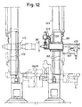
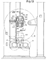
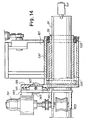
- Figs. 12-14 show a different embodiment of the mandrel withdrawal and insertion device. These figures show an arrangement in which the mandrel and its associated insertion and withdrawal system are mounted on a vertically mobile slide. This enables this withdrawal system also to be used in a machine in which the lower winding rolls 11 and 13 are of fixed axis.
- the withdrawal and insertion device constructed as in Figs. 4 and 5 could likewise be mounted on a raising and lowering system, for the same reasons.
- the mandrel, still numbered 31 is inserted axially into a sleeve still marked 33 and supported by bearings 135 in a housing 137.
- Fixed to the latter is a plate 139 supporting two horizontal guides 141. On these guides two slides 143 move in opposite directions along the guides 141 as shown by the arrow f143 (Fig. 13).
- the translational motion is provided by a motor 145 via a threaded bar 147.
- each slide 143 Mounted on each slide 143 is a pneumatic or hydraulic motor 151 providing motion to a respective shaped roll 153 equivalent to the shaped roll 47.
- the operation of the insertion and withdrawal device described above is similar to that of the device shown in Figs. 4 and 5.
- the shaped rolls 153 are pressed, by the motor 145, against the cylindrical surface of the mandrel 31, and rotation in either direction by the motors 143 causes withdrawal or insertion of the mandrel relative to the winding zone.
- a supporting roll 155 mounted idly on a projecting bracket 157.
- This roll serves as a support for the mandrel 31 when the latter is drawn out of the winding zone by the shaped rolls 153.
- the number 171 indicates a mating center able to move vertically up and down guides 173 on the opposite side frame from that where the shaped rolls 153 are located. The mating center holds the unsupported end of the mandrel 31.
- the embodiment of Figs. 12-14 is characterized by a reduction in the size and weight of the shaped rolls.
- a rewinding machine for the production of reels of wound weblike material, of the type that comprises in combination: a pair of lower winding rolls defining a winding cradle and means for inserting an axial mandrel into said winding cradle.
- the means for inserting the mandrel comprise a pair of shaped rolls with actuators which move said shaped rolls into contact with the outer surface of the mandrel and with other actuators that rotate one or both of the shaped rolls in order to move the mandrel parallel to its own axis, in such a way as to give this mandrel alternate movements of insertion into the winding cradle and withdrawal from the winding cradle. If the winding rolls have fixed axes the mandrel insertion and withdrawal means are vertically movable in order to follow the growth of the reel as it develops on the rolls.
Abstract
Description
- The present invention relates to a winding or rewinding machine for the production of reels of wound weblike material, such as reels of paper, nonwoven or the like.
- More specifically, the present invention relates to a machine of the kind that comprises a pair of lower supporting rolls on which is formed the roll or reel of weblike material or a plurality of axially aligned reels, and means for inserting winding cores into a cradle defined by said two rolls.
- Reels of weblike material of relatively large diameter are currently produced on winding or rewinding machines comprising a pair of motorized lower rolls, also known as traction rolls, on which is laid a tubular member or winding core on which the reel of material is formed. Above the two motorized lower rolls there is usually a movable third or pressure winding roll which follows the growth of the reel during winding and allows the pressure on it to be adjusted in order to achieve uniform winding.
- Machines of this kind are usually equipped with blades that cut the incoming weblike material to divide it into longitudinal strips which are then wound onto a plurality of separate, axially aligned winding cores in order to simultaneously produce a plurality of reels. This text will refer in a general way to the winding of a reel but it is intended that this term should be understood as meaning either a single reel or a plurality of axially aligned reels formed simultaneously by the winding of strips of weblike material.
- Machines of this kind are described, for example, in US-A-4,422,588, US-A-4,157,794, US-A-3,727,854, US-A-4,456,190, US-A-4,338,147, US-A-3,057,572, US-A-4,811,915, US-A-4,817,883, US-A-3,841,578, GB-A-2,087,362 and GB-A-2,050,317.
- In known rewinding machines of this type, the lower rolls have fixed axes and the reel of weblike material that is being wound grows with a gradual movement of the reel axis away from the winding cradle defined by the two lower winding rolls, also known as supporting rolls. US-A-3,841,578 also provides for a movement of the axes of the lower winding rolls, but this is only in order to allow insertion of the winding core which is inserted from below after a certain quantity of weblike material has been wound onto it.
- In many cases, owing to the great weight of material which is wound onto the reel, a mandrel is inserted inside the tubular winding core to stiffen the reel axially during the winding process.
- When a winding mandrel is used inside the tubular core, its vertical movement during the winding process places limits on its use and on the functions which it can perform during the winding.
- The invention relates to an improvement to the means for inserting winding cores into the winding cradle.
- According to the invention a rewinding machine for the production of reels of wound weblike material, including a pair of lower winding rolls defining a winding cradle and insertion means for inserting an axial mandrel into said winding cradle, is provided with insertion means comprising a pair of shaped rolls with first actuators means which move said shaped rolls into contact with the outer surface of the mandrel and with second actuator means that rotate one or both of the shaped rolls in order to move the mandrel parallel to its own axis.
- Further advantageous features and embodiments of the machine according to the invention are set forth in the dependent claims.
- A clearer understanding of the invention will be gained from the description and attached drawing, the latter showing a practical, non-restrictive example of an embodiment of the invention. In the drawing:
- Fig. 1 shows a schematic side view of the machine according to the invention;
- Fig. 2 shows a plan view on II-II as marked in Fig. 1;
- Fig. 3 shows a plan view of the withdrawal means for withdrawing the winding mandrel;
- Fig. 4 shows a front view on IV-IV as marked in Fig. 3;
- Figs. 5 and 6 show views similar to those of Figs. 3 and 4 for a larger-diameter mandrel;
- Fig. 7 shows a partly sectioned view on VII-VII as marked in Fig. 1, of the drive of the mandrel;
- Figs. 8-11 show various conditions of the machine in side view during the work cycle;
- Fig. 12 shows a side view of a different mandrel drive system;
- Fig. 13 shows a view on XIII-XIII as marked in Fig. 12; and
- Fig. 14 shows an enlarged section on XIV-XIV as marked in Fig. 13.
-
- The machine, which is given the
general reference 1, comprises a pair ofside frames arms arms 7, pivoted about an axis A-A, carries a firstlower winding roll 11, while the second pair ofarms 9, pivoted about an axis B-B, carries a secondlower winding roll 13. The twowinding rolls general references respective arm - Above the two
lower winding rolls third winding roll 15 carried by a pair of pivotingarms 17 hinged about an axis C-C to theside frames number 16 denotes an actuator used to raise and lower theroll 15. - The
lower winding rolls motors lower winding rolls velocity joints 25, 27 (see Fig. 2). In this way the twolower winding rolls motors respective winding rolls side frames arms lower winding rolls - Mounted on the
side frame 3 of the machine is anothermotor 29 used to turn amandrel 31 indicated by dots and dashes in Fig. 2, located in an essentially fixed axial position such as to allow its insertion into a tubular core, or into a series of tubular cores lined up axially in the cradle defined between thelower winding rolls mandrel 31. Themandrel 31 is of expandable type (known to those skilled in the art) and is inserted into asleeve 33 supported bybearings 35 in theside frame 3. Expansion of themandrel 31 locks it axially inside thesleeve 33. Keyed to the latter is apulley 37 carrying abelt 39 which takes its motion from themotor 29 via adrive pulley 41. With this arrangement, when themandrel 31 is not in its expanded condition, it can be slid axially through thesleeve 33 for insertion into and withdrawal from the winding zone defined between thelower winding rolls upper winding roll 15, while maintaining an essentially fixed axial position. - Axial movement of the
mandrel 31 is obtained with an arrangement illustrated in Figs. 3 and 4 and omitted in order to keep the drawing clear in Figs. 1 and 2. Hinged to theside frame 3 are twosupports 43 supporting respective gearedmotors 45 which drive twoshaped rolls 47 covered in a material with a high coefficient of friction, rubber for example. The twosupports 43 can be pivoted aboutrespective hinges 49 by two cylinder-and-piston actuators 51. In this way the twoshaped rolls 47 can be moved either into or out of contact with the cylindrical surface of themandrel 31. When it is wished to move themandrel 31 axially, theshaped rolls 47 are pressed against the surface of the mandrel and rotated by the gearedmotors 45. - As can be seen by comparison of Figs. 3, 4 and 5, 6, the system can easily be adapted to
mandrels 31 of different diameters, Figs. 5 and 6 showing a mandrel of larger diameter than that shown in Figs. 3 and 4. - Lower down, beneath the
lower winding rolls machine 1 stands is a winding core introducing means schematically depicted by a cylinder-and-piston system 61 whoserod 65 carries a V section. The tubular cores A (see Fig. 1) are placed on the V section from the exterior by an insertion movement parallel to the axis of the tubular cores. - The
number 67 is a general reference for a system of adjustable blades located in the inlet zone where the weblike material N enters themachine 1. The blades are of a type known per se and will not be explained in further detail here. - On the output side of the
machine 1 is acarriage 71 traveling ontracks 73 ending under the firstlower winding roll 11. Thecarriage 71 is equipped with apivoting cradle 75 designed to take the reels formed by themachine 1. Its pivoting is controlled by anactuator 77. Thepivoting cradle 75 can be raised and lowered vertically to receive reels of varying dimensions. - The operation of the machine will be described below with reference to Figs. 8-11. Shown in Fig. 8 is the condition of the machine at the start of the winding cycle. A new tubular core A, or a series of axially aligned tubular cores A, has been inserted into the winding cradle and the
lower winding rolls upper winding roll 15 is in its lowest position. The threerolls mandrel 31 has been inserted into the tubular cores and expanded so as to grip them. The rotation of themandrel 31 by themotor 29 and the rotation of the lower windingrolls blades 67 into longitudinal strips, so that one strip of weblike material is wound onto each of the tubular cores positioned on themandrel 31. If it is wished to produce a single reel of large axial dimension, the weblike material N may reach the winding zone without first being cut. In this case one tubular winding core is placed on the windingmandrel 31. - As the reel or reels of weblike material increase in diameter, the lower winding
rolls nut actuators roll 15 is gradually raised by theactuator 16. In this way the axis of the developing reel is kept essentially stationary and coinciding with the axis of rotation of themandrel 31. The gradual lowering and separating of the lower windingrolls - Fig. 9 shows the condition of the machine when the winding cycle has been completed and the reel R has reached its final diameter. The lower winding
rolls roll 15 is in the raised position. At this point the reel R must be unloaded onto thecradle 75 of thecarriage 71, the weblike material must be cut transversely to generate a new free end, and a new tubular core or new series of tubular cores must be inserted into the winding zone. - For this purpose the
carriage 71 is brought up to themachine 1 by a movement in the direction shown by the arrow f71 (Fig. 9) along thetracks 73, and its top part, on which thecradle 75 is hinged, is raised to the position shown in Fig. 10. Themandrel 31 is reduced in size and withdrawn from inside the tubular cores A on which the reel R has been formed. - The lower winding
roll 13, i.e. that furthest from thecarriage 71, is pivoted up about the axis B-B while the upper windingroll 15 may if desired be moved further upward to facilitate the unloading of the reel R. In this way the reel R is unloaded from thecradle 75 by rolling it in the direction of the arrow fR over the lower windingroll 11. In the meantime a new series of cores A, provided with a line of glue applied in a manner known per se, has been placed in readiness on thesection 65 of the core introducing means. - During unloading of the finished reel and insertion of the new cores A into the winding zone the weblike material has basically ceased to be fed in, except for a very small amount of material necessary to allow the reel R to roll into the tilting
cradle 75 without tearing the weblike material. - Fig. 11 shows the next stage, in which the reel R has been unloaded onto the
cradle 75, and the latter has been pivoted by theactuator 77 and lowered back down. The lower windingroll 13 has again been lowered from the position of Fig. 10, for the purposes described later, the lower windingroll 11 is still in the down position and the upper windingroll 15 has been moved back down. A cutting system mounted on the pivotingarms 17 of theroll 15 can at this point cut the weblike material N transversely, between the reel R and the lower windingroll 13. The cutting means (not shown) may for example comprise a system of air nozzles, a retractable blade or other means known per se or otherwise within the capabilities of those skilled in the art. Alternatively the material may also be cut by means arranged differently but known per se. - The lowering of the lower winding
roll 13 from the position of Fig. 10 to that of Fig. 11 allows the introducing means 63 of the cores A to be moved upward so that theV section 65 positions the new cores A in the winding zone, in line with themandrel 31. To facilitate the introduction, without excessively lowering theroll 13, provision may be made for the introducing means 63 to have a stroke inclined to the vertical. - Once the cores are lined up with the mandrel, the mandrel is inserted axially into the tubular cores so that the introducing means 63 can then be lowered. Once the tubular cores have been raised above the lower winding
roll 13 and the introducing means 63 retracted, the winding rolls 11, 13 can be raised again to return to the position of Fig. 8. - Lifting the cores into the winding zone may pinch the weblike material between the cores and the upper winding
roll 15, and possibly also cause the weblike material to stick to the tubular cores because of the applied glue. At this point the position shown in Fig. 8 has been reached once again and a new winding cycle can be commenced. - Cutting may conveniently be synchronized with the movements, described above, of the
rolls means 63. - Figs. 12-14 show a different embodiment of the mandrel withdrawal and insertion device. These figures show an arrangement in which the mandrel and its associated insertion and withdrawal system are mounted on a vertically mobile slide. This enables this withdrawal system also to be used in a machine in which the lower winding
rolls - In the embodiment shown in Figs.12-14 the mandrel, still numbered 31, is inserted axially into a sleeve still marked 33 and supported by
bearings 135 in ahousing 137. Fixed to the latter is aplate 139 supporting twohorizontal guides 141. On these guides twoslides 143 move in opposite directions along theguides 141 as shown by the arrow f143 (Fig. 13). The translational motion is provided by amotor 145 via a threadedbar 147. - Mounted on each
slide 143 is a pneumatic orhydraulic motor 151 providing motion to a respective shapedroll 153 equivalent to the shapedroll 47. The operation of the insertion and withdrawal device described above is similar to that of the device shown in Figs. 4 and 5. The shaped rolls 153 are pressed, by themotor 145, against the cylindrical surface of themandrel 31, and rotation in either direction by themotors 143 causes withdrawal or insertion of the mandrel relative to the winding zone. - Also shown in Fig. 12 is a supporting
roll 155 mounted idly on a projectingbracket 157. This roll serves as a support for themandrel 31 when the latter is drawn out of the winding zone by the shaped rolls 153. Thenumber 171 indicates a mating center able to move vertically up and down guides 173 on the opposite side frame from that where the shaped rolls 153 are located. The mating center holds the unsupported end of themandrel 31. - Compared with the embodiment illustrated in Figs. 3 and 4, the embodiment of Figs. 12-14 is characterized by a reduction in the size and weight of the shaped rolls.
- This makes simpler any movement in a vertical direction of the complete assembly made up of the shaped rolls, their associated drives and the support of the
mandrel 31. In Figs. 12-14 this assembly of mechanical members is mounted on acarriage 161 capable of vertical movement indicated by the double arrow f161 up and downvertical guides 163 fixed to theside frame 165 of the machine. In this way themandrel 31 insertion and withdrawal device can also be mounted on rewinding machines in which the lower windingrolls - With an insertion and withdrawal device of this type it is possible to construct a rewinding machine for the production of reels of wound weblike material, of the type that comprises in combination: a pair of lower winding rolls defining a winding cradle and means for inserting an axial mandrel into said winding cradle. The means for inserting the mandrel comprise a pair of shaped rolls with actuators which move said shaped rolls into contact with the outer surface of the mandrel and with other actuators that rotate one or both of the shaped rolls in order to move the mandrel parallel to its own axis, in such a way as to give this mandrel alternate movements of insertion into the winding cradle and withdrawal from the winding cradle. If the winding rolls have fixed axes the mandrel insertion and withdrawal means are vertically movable in order to follow the growth of the reel as it develops on the rolls.
- It will be understood that the drawing shows only an illustrative embodiment purely by way of a practical demonstration of the invention, which invention may be altered in its shapes and arrangements without thereby departing from the scope of the concept on which the invention is based. The presence of any reference numerals in the attached claims is for the purpose for facilitating the reading of the claims with reference to the drawings and does not limit the scope of protection thereof.
Claims (6)
- A rewinding machine for the production of reels (R) of wound weblike material (N), including: a pair of lower winding rolls (11, 13) defining a winding cradle and insertion means for inserting an axial mandrel (31) into said winding cradle, characterized in that said insertion means comprise a pair of shaped rolls (47; 153) with first actuators means (51; 145, 147) which move said shaped rolls into contact with the outer surface of the mandrel and with second actuator means (45; 151) that rotate one or both of the shaped rolls in order to move the mandrel parallel to its own axis.
- Rewinding machine according to claim 1, characterized in that said shaped rolls (47; 153) are addjustable to enable them to act on winding mandrels of variable diameter.
- Rewinding machine according to claim 1 or 2, characterized in that said mandrel insertion means are vertically movable in order to follow the growth of the reel (R) as it devevlops on the rolls (11, 13).
- Rewinding machine according to one or more of the preceding claims, characterized in that said shaped rolls (153) and said second actuator means (151) are mounted on respective slides (143), said slides being movable in opposite directions along guides (141).
- Rewinding machine according to claim 4, characterized in that said slides (143) are moved along said guides (141) by a threaded bar (147) and a motor (145).
- Rewinding machine according to claim 1, 2 or 3, characterized in that said shaped rolls (47) and said second actuator means (45) are supported by two supports (43) hinged on a side frame (3) of the machine, said supports being pivoted about respective hinges (49) by said first actuator means (51).
Applications Claiming Priority (3)
| Application Number | Priority Date | Filing Date | Title |
|---|---|---|---|
| IT98FI000131A ITFI980131A1 (en) | 1998-06-01 | 1998-06-01 | WINDING OR REWINDING MACHINE FOR THE FORMATION OF ROLLS OF BIG DIAMETER TAPE MATERIAL |
| ITFI980131 | 1998-06-01 | ||
| EP99830323A EP0962411B1 (en) | 1998-06-01 | 1999-05-27 | Winding machine for forming large-diameter reels of weblike material |
Related Parent Applications (1)
| Application Number | Title | Priority Date | Filing Date |
|---|---|---|---|
| EP99830323A Division EP0962411B1 (en) | 1998-06-01 | 1999-05-27 | Winding machine for forming large-diameter reels of weblike material |
Publications (3)
| Publication Number | Publication Date |
|---|---|
| EP1070675A2 true EP1070675A2 (en) | 2001-01-24 |
| EP1070675A3 EP1070675A3 (en) | 2001-09-12 |
| EP1070675B1 EP1070675B1 (en) | 2004-04-14 |
Family
ID=11352582
Family Applications (2)
| Application Number | Title | Priority Date | Filing Date |
|---|---|---|---|
| EP99830323A Expired - Lifetime EP0962411B1 (en) | 1998-06-01 | 1999-05-27 | Winding machine for forming large-diameter reels of weblike material |
| EP00120695A Expired - Lifetime EP1070675B1 (en) | 1998-06-01 | 1999-05-27 | Winding machine for forming large-diameter reels of web material with mandrel insertion means |
Family Applications Before (1)
| Application Number | Title | Priority Date | Filing Date |
|---|---|---|---|
| EP99830323A Expired - Lifetime EP0962411B1 (en) | 1998-06-01 | 1999-05-27 | Winding machine for forming large-diameter reels of weblike material |
Country Status (8)
| Country | Link |
|---|---|
| US (1) | US6199789B1 (en) |
| EP (2) | EP0962411B1 (en) |
| AT (2) | ATE221021T1 (en) |
| CA (2) | CA2273370C (en) |
| DE (2) | DE69916444T2 (en) |
| DK (1) | DK0962411T3 (en) |
| ES (1) | ES2180264T3 (en) |
| IT (1) | ITFI980131A1 (en) |
Cited By (6)
| Publication number | Priority date | Publication date | Assignee | Title |
|---|---|---|---|---|
| EP1306332A2 (en) * | 2001-10-29 | 2003-05-02 | Bielloni Castello S.P.A. | Automatic rewinder particularly for flexible film of plastic material and relative method for producing rolls |
| WO2003093151A1 (en) * | 2002-04-30 | 2003-11-13 | Kimberly-Clark Worldwide, Inc. | Apparatus and method for producing logs of sheet material |
| US6948678B2 (en) | 2002-06-25 | 2005-09-27 | A. Celli Nonwovens S.P.A. | Rewinding machine with auxiliary cylinders and respective winding method |
| US8353662B2 (en) | 2006-07-17 | 2013-01-15 | A. Celli Nonwovens S.P.A. | Robot for handling rolls |
| WO2015056194A1 (en) | 2013-10-18 | 2015-04-23 | A.Celli Paper S.P.A. | A winding rod for reels of web material and a winding machine using said rod |
| CN106348066A (en) * | 2016-09-26 | 2017-01-25 | 东莞市联洲知识产权运营管理有限公司 | Mobile type automobile adhering film winding device |
Families Citing this family (22)
| Publication number | Priority date | Publication date | Assignee | Title |
|---|---|---|---|---|
| DE19960000A1 (en) * | 1999-12-13 | 2001-07-05 | Voith Sulzer Papiertech Patent | Roll winding device, in particular for a roll cutting machine |
| ES2254357T3 (en) | 2001-01-16 | 2006-06-16 | Fabio Perini S.P.A. | REWINDING MACHINE TO REWIND MATERIAL IN CONTINUOUS BAND IN A NUCLEO TO FORM ROLLS AND CORRESPONDING WINDING METHOD. |
| FI116282B (en) * | 2002-04-02 | 2005-10-31 | Metso Paper Inc | Method and apparatus for winding a paper or board web, particularly a tissue paper web |
| JP3504251B2 (en) * | 2002-05-14 | 2004-03-08 | 株式会社西村製作所 | Slitter winding device |
| ITFI20040061A1 (en) * | 2004-03-18 | 2004-06-18 | Perini Fabio Spa | PERIPHERAL AND CENTRAL COMBINED REWINDING MACHINE |
| US7546971B2 (en) * | 2005-04-06 | 2009-06-16 | Catbridge Machinery, L.L.C. | System, apparatus and method for unloading rolled material from a supporting structure |
| DE102005000171A1 (en) * | 2005-11-28 | 2007-05-31 | Voith Patent Gmbh | Winding machine for winding a material web |
| FI120442B (en) | 2006-08-28 | 2009-10-30 | Metso Paper Inc | A device for winding the web, in particular a rewinder |
| DE102007010094A1 (en) * | 2007-03-02 | 2008-09-11 | Karl Mayer Textilmaschinenfabrik Gmbh | Rolling up device for textile materials comprises a device for storing a winding body that consists of roller-like storage elements in the form of support rollers, drive rollers and/or pressure rollers acting externally on the winding body |
| BE1017663A3 (en) * | 2007-06-28 | 2009-03-03 | Handsaeme Machinery Bvba | ROLL-UP DEVICE AND METHOD FOR ROLLING UP A TISSUE. |
| DE102008018890A1 (en) * | 2008-04-14 | 2009-10-29 | Ancient Energy Gmbh & Co. Kg | Apparatus and method for winding web-shaped materials |
| NL2001673C2 (en) * | 2008-06-11 | 2009-12-14 | Otb Solar Bv | Transport table and method for its use. |
| IT1391147B1 (en) * | 2008-07-10 | 2011-11-18 | Guglielmo Biagiotti | APPARATUS, AND ITS METHOD, FOR THE TRANSFORMATION OF ADJACENT TAPES OF FLEXIBLE MATERIAL. |
| US9284147B2 (en) | 2012-09-21 | 2016-03-15 | Paper Converting Machine Company | Method and apparatus for producing coreless rolls of paper |
| CN107840174A (en) * | 2016-09-20 | 2018-03-27 | 佛山市宝索机械制造有限公司 | It is conveniently replaceable the rewinding machine of parts |
| EP4116245A1 (en) | 2017-11-29 | 2023-01-11 | Paper Converting Machine Company | Surface rewinder with center assist and belt and winding drum forming a winding nest |
| US11247863B2 (en) | 2018-11-27 | 2022-02-15 | Paper Converting Machine Company | Flexible drive and core engagement members for a rewinding machine |
| CN109716882B (en) * | 2019-03-18 | 2024-02-02 | 石河子大学 | Incomplete membrane is retrieved rolling membrane and is unloaded membrane device |
| US11383946B2 (en) | 2019-05-13 | 2022-07-12 | Paper Converting Machine Company | Solid roll product formed from surface rewinder with belt and winding drum forming a winding nest |
| IT201900012891A1 (en) * | 2019-07-25 | 2021-01-25 | Mec Ind Srl | MACHINE FOR WINDING FABRICS IN COMPOSITE MATERIAL ON A SPINDLE |
| CN112520497B (en) * | 2020-11-21 | 2021-09-17 | 苏州宸浩纺织科技有限公司 | Cotton thread winding device for spinning |
| CN114108176B (en) * | 2021-11-29 | 2023-03-31 | 浙江真爱毯业科技有限公司 | Shaft unloading device of coiling mechanism of double-needle-bed double-width warp knitting machine |
Citations (3)
| Publication number | Priority date | Publication date | Assignee | Title |
|---|---|---|---|---|
| US2913098A (en) * | 1957-01-02 | 1959-11-17 | Western Gear Corp | Core-loader for winding machine |
| GB1324183A (en) * | 1969-08-15 | 1973-07-18 | Lilla Edets Pappersbruks Ab | Device for the application of cardboard winding tubes on rotatably driven spindles in roll-manufacturing machines |
| US4299358A (en) * | 1979-01-22 | 1981-11-10 | Jagenberg-Werke A.G. | Method and apparatus for the automatic sidewise insertion of cores in winding machines |
Family Cites Families (27)
| Publication number | Priority date | Publication date | Assignee | Title |
|---|---|---|---|---|
| US1875861A (en) * | 1927-09-09 | 1932-09-06 | George F Eckstein | Winding machine |
| US2090130A (en) * | 1931-05-18 | 1937-08-17 | John J Kittel | Slitting and winding machine |
| US2141629A (en) * | 1937-05-08 | 1938-12-27 | John Waldron Corp | Rewinder |
| DE740707C (en) * | 1941-04-09 | 1943-10-27 | Goebel Ag | Double support roller for material webs made of paper or the like. |
| US2736508A (en) * | 1952-02-21 | 1956-02-28 | Langbo Georg | Winding machine for paper rolls |
| US2772838A (en) * | 1953-11-03 | 1956-12-04 | Jagenberg Werke Ag | Mechanism for extracting the rewind shaft from a core of a rewound roll and inserting this shaft into the core of a roll to be rewound |
| US3057572A (en) | 1960-01-05 | 1962-10-09 | Cameron Machine Co | Winding machine |
| DE1452199A1 (en) * | 1964-01-13 | 1968-12-19 | Achenbach Soehne Gmbh | Decoiler on one-way rolling mills with a turntable in front of the rolling stand |
| JPS4836408B1 (en) * | 1970-07-07 | 1973-11-05 | ||
| DE2037006C3 (en) | 1970-07-25 | 1986-10-02 | Hergeth Hollingsworth GmbH, 4408 Dülmen | Device for feeding and inserting rod-shaped or tubular winding cores of a support roller winding machine when changing laps |
| US3675866A (en) * | 1970-12-28 | 1972-07-11 | Murray Machinery Inc | Apparatus for handling pneumatic web roll winding shafts |
| DE2118963C3 (en) | 1971-04-20 | 1974-01-17 | A. Ahlstroem Oy, Helsinki | Method and device for continuously winding up webs of material in individual rolls and device for carrying out the method |
| US3995747A (en) * | 1974-08-13 | 1976-12-07 | Burlington Industries, Inc. | Apparatus for handling large fabric rolls for slitting |
| DE2638368C2 (en) | 1976-08-26 | 1983-08-25 | J.M. Voith Gmbh, 7920 Heidenheim | Process and double roller winding machine for changing laps after winding webs |
| NO790519L (en) | 1978-06-21 | 1979-12-27 | Ahlstroem Oy | SPIRAL WRAPPED SLEEVE, METHOD FOR MANUFACTURING THE SLEEVE, PROCEDURE FOR USING THE SLEEVE IN A WRAPPING APPLIANCE AND DEVICE FOR USING THE SLEEVE |
| US4223850A (en) * | 1979-02-28 | 1980-09-23 | Alexander Iii William J | Surface wind batcher and method of collecting material in roll form |
| DE2920707C2 (en) | 1979-05-22 | 1990-05-31 | Jagenberg-Werke AG, 4000 Düsseldorf | Process and double roller winding machine for automatically separating and winding a web of material |
| FI63918C (en) | 1980-10-21 | 1983-09-12 | Waertsilae Oy Ab | ANORDNING FOER RULLNING AV PAPPERSBANOR |
| GB2087362A (en) | 1980-11-14 | 1982-05-26 | Masson Scott Thrissell Eng Ltd | Winding web at constant winding density |
| JPS57141342A (en) * | 1981-02-24 | 1982-09-01 | Kataoka Kikai Seisakusho:Kk | Winding device with mechanism to draw out shaft |
| US4422588A (en) | 1981-09-28 | 1983-12-27 | The Black Clawson Company | Slitter-rewinder system |
| FR2559464B1 (en) * | 1984-02-10 | 1986-06-27 | Valisere Sa | DEVICE FOR WINDING A FABRIC DURING DIFFERENT PHASES OF ITS MANUFACTURE |
| DE3614436A1 (en) | 1986-04-29 | 1987-11-05 | Jagenberg Ag | MEASURING DEVICE FOR THE PRINT ZONE WIDTH AND / OR AREA PRESSING BETWEEN A REEL OF A MATERIAL AND A ROLL PRESSED AGAINST THE REEL, AND METHOD FOR WINDING A MATERIAL |
| US4811915A (en) | 1987-11-12 | 1989-03-14 | The Black Clawson Company | Rider roll relieving system |
| EP0754640B1 (en) * | 1993-08-24 | 1999-01-27 | Beloit Technologies, Inc. | Winder for winding webs |
| JP4063318B2 (en) * | 1995-05-15 | 2008-03-19 | メリター・オートモーティヴ・インコーポレーテッド | Brake lining pressing device for disc brake |
| US6047916A (en) * | 1998-03-16 | 2000-04-11 | Valmet-Karlstad Ab | Reel-up and multi-functional handling device therefor |
-
1998
- 1998-06-01 IT IT98FI000131A patent/ITFI980131A1/en unknown
-
1999
- 1999-05-27 AT AT99830323T patent/ATE221021T1/en not_active IP Right Cessation
- 1999-05-27 ES ES99830323T patent/ES2180264T3/en not_active Expired - Lifetime
- 1999-05-27 AT AT00120695T patent/ATE264248T1/en not_active IP Right Cessation
- 1999-05-27 EP EP99830323A patent/EP0962411B1/en not_active Expired - Lifetime
- 1999-05-27 DE DE69916444T patent/DE69916444T2/en not_active Expired - Fee Related
- 1999-05-27 DK DK99830323T patent/DK0962411T3/en active
- 1999-05-27 EP EP00120695A patent/EP1070675B1/en not_active Expired - Lifetime
- 1999-05-27 DE DE69902208T patent/DE69902208T2/en not_active Expired - Fee Related
- 1999-05-28 US US09/322,578 patent/US6199789B1/en not_active Expired - Fee Related
- 1999-05-31 CA CA002273370A patent/CA2273370C/en not_active Expired - Fee Related
- 1999-05-31 CA CA002626381A patent/CA2626381C/en not_active Expired - Fee Related
Patent Citations (3)
| Publication number | Priority date | Publication date | Assignee | Title |
|---|---|---|---|---|
| US2913098A (en) * | 1957-01-02 | 1959-11-17 | Western Gear Corp | Core-loader for winding machine |
| GB1324183A (en) * | 1969-08-15 | 1973-07-18 | Lilla Edets Pappersbruks Ab | Device for the application of cardboard winding tubes on rotatably driven spindles in roll-manufacturing machines |
| US4299358A (en) * | 1979-01-22 | 1981-11-10 | Jagenberg-Werke A.G. | Method and apparatus for the automatic sidewise insertion of cores in winding machines |
Cited By (8)
| Publication number | Priority date | Publication date | Assignee | Title |
|---|---|---|---|---|
| EP1306332A2 (en) * | 2001-10-29 | 2003-05-02 | Bielloni Castello S.P.A. | Automatic rewinder particularly for flexible film of plastic material and relative method for producing rolls |
| EP1306332A3 (en) * | 2001-10-29 | 2004-01-14 | Bielloni Castello S.P.A. | Automatic rewinder particularly for flexible film of plastic material and relative method for producing rolls |
| WO2003093151A1 (en) * | 2002-04-30 | 2003-11-13 | Kimberly-Clark Worldwide, Inc. | Apparatus and method for producing logs of sheet material |
| US6948678B2 (en) | 2002-06-25 | 2005-09-27 | A. Celli Nonwovens S.P.A. | Rewinding machine with auxiliary cylinders and respective winding method |
| US8353662B2 (en) | 2006-07-17 | 2013-01-15 | A. Celli Nonwovens S.P.A. | Robot for handling rolls |
| US8413407B2 (en) | 2006-07-17 | 2013-04-09 | A. Celli Nonwovens S.P.A. | Automated system for producing and managing rolls of web material |
| WO2015056194A1 (en) | 2013-10-18 | 2015-04-23 | A.Celli Paper S.P.A. | A winding rod for reels of web material and a winding machine using said rod |
| CN106348066A (en) * | 2016-09-26 | 2017-01-25 | 东莞市联洲知识产权运营管理有限公司 | Mobile type automobile adhering film winding device |
Also Published As
| Publication number | Publication date |
|---|---|
| EP0962411A1 (en) | 1999-12-08 |
| DE69902208T2 (en) | 2003-08-21 |
| CA2626381A1 (en) | 1999-12-01 |
| CA2626381C (en) | 2009-02-24 |
| ATE221021T1 (en) | 2002-08-15 |
| DK0962411T3 (en) | 2002-10-14 |
| DE69916444D1 (en) | 2004-05-19 |
| ATE264248T1 (en) | 2004-04-15 |
| EP1070675B1 (en) | 2004-04-14 |
| CA2273370A1 (en) | 1999-12-01 |
| ITFI980131A1 (en) | 1999-12-01 |
| ES2180264T3 (en) | 2003-02-01 |
| CA2273370C (en) | 2009-02-24 |
| DE69916444T2 (en) | 2005-12-22 |
| EP0962411B1 (en) | 2002-07-24 |
| DE69902208D1 (en) | 2002-08-29 |
| US6199789B1 (en) | 2001-03-13 |
| EP1070675A3 (en) | 2001-09-12 |
Similar Documents
| Publication | Publication Date | Title |
|---|---|---|
| EP1070675B1 (en) | Winding machine for forming large-diameter reels of web material with mandrel insertion means | |
| CA1318900C (en) | Apparatus for winding webs of material | |
| GB2274835A (en) | Web slitting and rewinding | |
| JPH09510171A (en) | Improved method and apparatus for winding a moving web into a wound roll of web | |
| CN111483853A (en) | Wide plastic film winding and changing equipment and method without mandrel center winding mode | |
| US5273222A (en) | Multiple-station winding machine for the winding of webs of foil or the like | |
| US4951894A (en) | Method and apparatus for handling rolls of textile fabrics and other webs | |
| EP1375401A1 (en) | Rewinding machine with auxiliary cylinders and respective winding method | |
| JP2002540032A (en) | Apparatus and method for rewinding reels of web material | |
| CN110790056A (en) | Automatic unwinding system without stopping and reducing speed | |
| CA1315532C (en) | Apparatus for helically slitting a continuous tubular film or synthetic thermoplastic material | |
| US6149098A (en) | Process to spool a longitudinally cut material sheet and a device to execute the process | |
| US5360180A (en) | Roll-support system for paper-winding machine | |
| MXPA00009603A (en) | Center driven side shuttle unwinder. | |
| WO2003022721A1 (en) | Self-lifting shaftless unwind stand | |
| EP1375402A1 (en) | Rewinding machine with means for axially pulling the winding mandrel | |
| CN219216946U (en) | Die-cutting winding mechanism | |
| JP3482041B2 (en) | Tape application device | |
| CN113120669A (en) | Full-automatic four-axis cutting machine | |
| US5364044A (en) | Air-cushion roll support in roll-making machine | |
| EP0387365B1 (en) | Mill roll stand | |
| US6213423B1 (en) | Self-lifting shaftless unwind stand | |
| CN219259051U (en) | Automatic guide roller adjusting device | |
| CN220351282U (en) | Cutting machine for operation drape production | |
| CN216980373U (en) | Capacitor aluminum shell tape winding device |
Legal Events
| Date | Code | Title | Description |
|---|---|---|---|
| PUAI | Public reference made under article 153(3) epc to a published international application that has entered the european phase |
Free format text: ORIGINAL CODE: 0009012 |
|
| AC | Divisional application: reference to earlier application |
Ref document number: 962411 Country of ref document: EP |
|
| AK | Designated contracting states |
Kind code of ref document: A2 Designated state(s): AT BE CH CY DE DK ES FI FR GB GR IE IT LI LU MC NL PT SE |
|
| PUAL | Search report despatched |
Free format text: ORIGINAL CODE: 0009013 |
|
| AK | Designated contracting states |
Kind code of ref document: A3 Designated state(s): AT BE CH CY DE DK ES FI FR GB GR IE IT LI LU MC NL PT SE |
|
| RIC1 | Information provided on ipc code assigned before grant |
Free format text: 7B 65H 18/20 A, 7B 65H 19/30 B |
|
| AKX | Designation fees paid | ||
| 17P | Request for examination filed |
Effective date: 20020301 |
|
| RBV | Designated contracting states (corrected) |
Designated state(s): AT BE CH CY DE DK ES FI FR GB GR IE IT LI LU MC NL PT SE |
|
| REG | Reference to a national code |
Ref country code: DE Ref legal event code: 8566 |
|
| 17Q | First examination report despatched |
Effective date: 20021219 |
|
| GRAP | Despatch of communication of intention to grant a patent |
Free format text: ORIGINAL CODE: EPIDOSNIGR1 |
|
| RAP1 | Party data changed (applicant data changed or rights of an application transferred) |
Owner name: A. CELLI NONWOVENS S.P.A. |
|
| GRAS | Grant fee paid |
Free format text: ORIGINAL CODE: EPIDOSNIGR3 |
|
| GRAA | (expected) grant |
Free format text: ORIGINAL CODE: 0009210 |
|
| RBV | Designated contracting states (corrected) |
Designated state(s): AT BE DE DK ES FI FR GB IT SE |
|
| AC | Divisional application: reference to earlier application |
Ref document number: 0962411 Country of ref document: EP Kind code of ref document: P |
|
| AK | Designated contracting states |
Kind code of ref document: B1 Designated state(s): AT BE DE DK ES FI FR GB IT SE |
|
| PG25 | Lapsed in a contracting state [announced via postgrant information from national office to epo] |
Ref country code: BE Free format text: LAPSE BECAUSE OF FAILURE TO SUBMIT A TRANSLATION OF THE DESCRIPTION OR TO PAY THE FEE WITHIN THE PRESCRIBED TIME-LIMIT Effective date: 20040414 |
|
| REG | Reference to a national code |
Ref country code: GB Ref legal event code: FG4D |
|
| REF | Corresponds to: |
Ref document number: 69916444 Country of ref document: DE Date of ref document: 20040519 Kind code of ref document: P |
|
| REG | Reference to a national code |
Ref country code: IE Ref legal event code: FG4D |
|
| PG25 | Lapsed in a contracting state [announced via postgrant information from national office to epo] |
Ref country code: DK Free format text: LAPSE BECAUSE OF FAILURE TO SUBMIT A TRANSLATION OF THE DESCRIPTION OR TO PAY THE FEE WITHIN THE PRESCRIBED TIME-LIMIT Effective date: 20040714 |
|
| REG | Reference to a national code |
Ref country code: SE Ref legal event code: TRGR |
|
| PG25 | Lapsed in a contracting state [announced via postgrant information from national office to epo] |
Ref country code: ES Free format text: LAPSE BECAUSE OF FAILURE TO SUBMIT A TRANSLATION OF THE DESCRIPTION OR TO PAY THE FEE WITHIN THE PRESCRIBED TIME-LIMIT Effective date: 20040725 |
|
| ET | Fr: translation filed | ||
| PLBE | No opposition filed within time limit |
Free format text: ORIGINAL CODE: 0009261 |
|
| STAA | Information on the status of an ep patent application or granted ep patent |
Free format text: STATUS: NO OPPOSITION FILED WITHIN TIME LIMIT |
|
| REG | Reference to a national code |
Ref country code: IE Ref legal event code: MM4A |
|
| 26N | No opposition filed |
Effective date: 20050117 |
|
| PGFP | Annual fee paid to national office [announced via postgrant information from national office to epo] |
Ref country code: AT Payment date: 20080529 Year of fee payment: 10 |
|
| PGFP | Annual fee paid to national office [announced via postgrant information from national office to epo] |
Ref country code: IT Payment date: 20080529 Year of fee payment: 10 Ref country code: FI Payment date: 20080527 Year of fee payment: 10 |
|
| PGFP | Annual fee paid to national office [announced via postgrant information from national office to epo] |
Ref country code: DE Payment date: 20080724 Year of fee payment: 10 Ref country code: SE Payment date: 20080512 Year of fee payment: 10 |
|
| PGFP | Annual fee paid to national office [announced via postgrant information from national office to epo] |
Ref country code: GB Payment date: 20080528 Year of fee payment: 10 |
|
| GBPC | Gb: european patent ceased through non-payment of renewal fee |
Effective date: 20090527 |
|
| PG25 | Lapsed in a contracting state [announced via postgrant information from national office to epo] |
Ref country code: AT Free format text: LAPSE BECAUSE OF NON-PAYMENT OF DUE FEES Effective date: 20090527 Ref country code: FI Free format text: LAPSE BECAUSE OF NON-PAYMENT OF DUE FEES Effective date: 20090527 |
|
| REG | Reference to a national code |
Ref country code: FR Ref legal event code: ST Effective date: 20100129 |
|
| PG25 | Lapsed in a contracting state [announced via postgrant information from national office to epo] |
Ref country code: FR Free format text: LAPSE BECAUSE OF NON-PAYMENT OF DUE FEES Effective date: 20090602 |
|
| PGFP | Annual fee paid to national office [announced via postgrant information from national office to epo] |
Ref country code: FR Payment date: 20080428 Year of fee payment: 10 |
|
| PG25 | Lapsed in a contracting state [announced via postgrant information from national office to epo] |
Ref country code: GB Free format text: LAPSE BECAUSE OF NON-PAYMENT OF DUE FEES Effective date: 20090527 |
|
| PG25 | Lapsed in a contracting state [announced via postgrant information from national office to epo] |
Ref country code: DE Free format text: LAPSE BECAUSE OF NON-PAYMENT OF DUE FEES Effective date: 20091201 |
|
| PG25 | Lapsed in a contracting state [announced via postgrant information from national office to epo] |
Ref country code: IT Free format text: LAPSE BECAUSE OF NON-PAYMENT OF DUE FEES Effective date: 20090527 |
|
| PG25 | Lapsed in a contracting state [announced via postgrant information from national office to epo] |
Ref country code: SE Free format text: LAPSE BECAUSE OF NON-PAYMENT OF DUE FEES Effective date: 20090528 |