EP1070592A1 - Imprimante à jet d'encre et procédé de son opération - Google Patents
Imprimante à jet d'encre et procédé de son opération Download PDFInfo
- Publication number
- EP1070592A1 EP1070592A1 EP00115461A EP00115461A EP1070592A1 EP 1070592 A1 EP1070592 A1 EP 1070592A1 EP 00115461 A EP00115461 A EP 00115461A EP 00115461 A EP00115461 A EP 00115461A EP 1070592 A1 EP1070592 A1 EP 1070592A1
- Authority
- EP
- European Patent Office
- Prior art keywords
- recording head
- cleaning liquid
- air
- ink
- jet printer
- Prior art date
- Legal status (The legal status is an assumption and is not a legal conclusion. Google has not performed a legal analysis and makes no representation as to the accuracy of the status listed.)
- Withdrawn
Links
Images


Classifications
-
- B—PERFORMING OPERATIONS; TRANSPORTING
- B41—PRINTING; LINING MACHINES; TYPEWRITERS; STAMPS
- B41J—TYPEWRITERS; SELECTIVE PRINTING MECHANISMS, i.e. MECHANISMS PRINTING OTHERWISE THAN FROM A FORME; CORRECTION OF TYPOGRAPHICAL ERRORS
- B41J2/00—Typewriters or selective printing mechanisms characterised by the printing or marking process for which they are designed
- B41J2/005—Typewriters or selective printing mechanisms characterised by the printing or marking process for which they are designed characterised by bringing liquid or particles selectively into contact with a printing material
- B41J2/01—Ink jet
- B41J2/17—Ink jet characterised by ink handling
- B41J2/1707—Conditioning of the inside of ink supply circuits, e.g. flushing during start-up or shut-down
-
- B—PERFORMING OPERATIONS; TRANSPORTING
- B41—PRINTING; LINING MACHINES; TYPEWRITERS; STAMPS
- B41J—TYPEWRITERS; SELECTIVE PRINTING MECHANISMS, i.e. MECHANISMS PRINTING OTHERWISE THAN FROM A FORME; CORRECTION OF TYPOGRAPHICAL ERRORS
- B41J2/00—Typewriters or selective printing mechanisms characterised by the printing or marking process for which they are designed
- B41J2/005—Typewriters or selective printing mechanisms characterised by the printing or marking process for which they are designed characterised by bringing liquid or particles selectively into contact with a printing material
- B41J2/01—Ink jet
- B41J2/135—Nozzles
- B41J2/165—Preventing or detecting of nozzle clogging, e.g. cleaning, capping or moistening for nozzles
- B41J2/16517—Cleaning of print head nozzles
- B41J2/16552—Cleaning of print head nozzles using cleaning fluids
Definitions
- the present invention relates to an ink jet printer or plotter according to the preamble of claim 1 and to a method according to the preamble of claim 6.
- a process employed is to apply liquid under pressure to the tube and to discharge the cleaning liquid at a discharge outlet of a purge box from an ink discharge hole of a nozzle of the recording head through the inside of the recording head.
- Object of the present invention is to solve or minimize the foregoing problems and to provide an ink jet printer and a method for operating an ink jet printer, in particular with improved printing quality and/or with improved cleaning features.
- the present invention is to perform effectively the cleaning of the ink passage of the inside of the recording head and of the ink passage communicating with the recording head, and to keep clear of the ink on the tube wall of the ink passage after the cleaning.
- the recording head is connected to an electromagnetic valve through the tube, and air, ink and cleaning liquid are selectively supplied to the tube through the electromagnetic valve.
- the recording head discharges a rich supply of ink droplets from the nozzle in a range of the plotting to a plotting medium in a controllable manner whereby the plotting is applied to the plotting or printing medium.
- the air and the cleaning liquid are alternately fed under pressure to the recording head through the electromagnetic valve, and the ink remaining in the tube and the recording head is discharged from the nozzle of the recording head at a discharge outlet along with the air and the cleaning liquid.
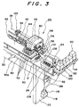
- reference numeral 22 denotes legs (illustration of the other is omitted) disposed at right and left of a base plate 26 of an ink jet printer 24, and the base plate 26 is fixed to upper ends of the legs.
- the legs 22 and the base plate 26 constitute a structure of the ink jet printer 24.
- an axial holder 28 is fixed, and an axial portion of a rolled paper holder 32 is rotatably and detachably journalled on the axial holder 28.
- a roll portion 30a of a plotting medium 30 wound in a roll type is detachably retained on the paper holder 32.
- a platen 34 (paper guide plate) is fixed to the base plate 26, and a guide roller 36 having a width and a length almost same with those of the plotting medium 30 that extends in a Y-axis direction is disposed in the vicinity of an upper flow end of the platen 34.
- the guide roller 36 is disposed in the upper part of the roll portion 30a of the rolled paper 30, and both ends of the guide roller 36 are rotatably journalled on the base plate 26 by means of a bracket.
- Reference numeral 38 denotes a Y axis rail, and is disposed horizontally in the upper part of the platen 34, and both ends are journalled on the base plate 26 by means of the bracket.
- a Y cursor 40 (carriage) is shiftably mounted on the Y axis rail 38, and the carriage 40 is connected to a Y axis drive device (not shown in the drawing) disposed on the base plate 26 by means of a steel belt 42 spanned endlessly between pulleys or the like.
- a slit is formed on the platen 34 along the Y axis direction, and a drive roller 44 is disposed on the slit.
- Both ends of the drive roller 44 are rotatably journalled on the base plate 26 by means of the bracket, and the drive roller 44 is connected to an X axis drive device (illustration is omitted) that is disposed on the base plate 26.
- a pinch roller shaft 46 is liftably mounted on the Y axis rail 38 by means of a resilient mechanism (illustration is omitted), and pinch rollers are rotatably fitted on the pinch roller shaft 46.
- the pinch roller shaft 46 is constructed so that it can be set on an either condition, a condition where it is separated from the surface of the drive roller 44 and a condition where it is in resilient state in horizontal to the surface.
- a head base 50 is fixed to one side of the carriage 40 and from ink jet recording heads 52 with four nozzles for four colors are mounted on the head base 50.
- the bottom surface disposed on mutually identical planes of four rows of the recording heads 52 is formed in an elongate rectangular shape, and the nozzles are disposed on the bottom surface to be slightly projected therefrom which have a plurality of ink discharge holes in a row.
- Each of the recording heads 52 of the four rows is disposed in parallel horizontally and mutually at a predetermined interval, and each of the bottom surfaces 52b is arranged with an angle alpha to an X axis forming a right angle to the Y axis rail 38.
- sub-tanks 54 for solvent ink of four colors black K, cyanogen C, magenta M, and yellow Y
- three-way electromagnetic valves 56 are respectively mounted on upper covers of the sub-tanks 54.
- each sub-tank 54 On each sub-tank 54, a sensor for detection of the level of the ink is provided.
- the insides of the ink supply passages, namely tubes 53 between the recording heads 52 and the corresponding sub-tanks 54 are maintained at negative pressure, in that the liquid upper surface of the sub-tanks 54 is disposed lower than the ink discharge outlet of the corresponding recording head 52.
- Reference numeral 58 denotes a main tank case disposed on the base plate 26, and main tanks 60 (illustration of three pieces are omitted) for four color solvent inks whose number is identical with the number of sub-tanks 54, and for a cleaning liquid tank 62 are detachably housed in the main tank case 58.
- Each tank 60 and 62 is supported by a spring, and is constructed in such way that the remaining quantities of the ink and the cleaning liquid are detected by sensors 136 and 138 consisting of limit switches disposed under each tank 60 and 62.
- the main tanks 60 and the sub-tanks 54 are communicated by tube cables by means of the electromagnetic valve.
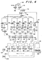
- Reference numeral 64 denotes a control box mounted on the base plate 26 and is built in with a pump 66 and electromagnetic valves 68, 70, 72, 74, 76, 78, 80, 82, 84, 86, 88, 90, 92, 94, 96, 98, 100, 101, and furthermore, an electronic control circuit unit for controlling these electronic equipments is provided. Also, on the base plate 26 of the printer 24, a controller (illustration is omitted) is provided for controlling the X and Y axis drive devices and the recording head 52 and the like.
- Reference numeral 2 denotes a wiping device for cleaning the nozzle peripheral portions of the bottom surfaces of the recording heads 52 and the discharge outlets of the nozzles, and a rubber made wiper is arranged to be reciprocally operated in an X axial direction by a wiper motor 102 (refer to Fig. 4).
- the wiper is formed with a V-groove, and when the nozzle at the lower surface of a recording head 52 is positioned in the V groove, it is possible to wipe the lower surface of the periphery of the nozzle of the recording head 52 excluding the nozzle by the wiper, and when the recording head is shifted to slide the V groove from the nozzle, the nozzle can be wiped by the wiper.
- Reference numeral 106 denotes a purge box having rubber caps 108 and a liquid discharge outlet 110 for covering the discharge outlets of a nozzles of the recording heads 52 alternately.
- the purge box 106 is disposed at the side of the base plate which is the outside of the plotting range and also, in the transfer range of the recording heads 52. It can be lifted by a motor 112 (refer to Fig. 4).
- the rubber caps 108 have an opening for receiving a liquid such as ink and the like.
- Each cap 108 and the discharge outlet 110 of the purge box 106 are connected to a collection pipe 120 fixed to the base plate 26 by means of the tube and the electromagnetic valve.
- Reference numeral 114 denotes a motor for stirring the ink in the main tanks 60
- 116 denotes a waste liquid tank case mounted on the leg 22, and 118 denotes a waste liquid tank.
- the waste liquid tank 118 is supported by a spring housed in the case 116, and is constructed in such a way that the quantity of the waste liquid is detected by a sensor 134 (refer to Fig. 4) consisting of limit switches disposed between the bottom surface of the tank 118 and the upper surface of the case 116.
- each main tank 60 a rotor made of magnetic material is rotatably journalled, and when a magnet (illustration is omitted) rotates by the drive of the motor 114, the rotor in the main tank rotates, and the ink in each main tank 60 is arranged to stir.
- Each component part and the device are connected by piping with tube as shown in FIG. 4.
- the recording heads 52 can be shifted to a position immediately above the purge box 106 which is off the plotting range by the transfer of the carriage 40 along the Y axis rail 38.
- the pinch rollers are lifted and the plotting medium 30 is drawn from the roll portion 30a and inserted between the drive roller 44 and the pinch rollers through a guide roller 36, and thereafter, the pinch rollers 48 are descented and made to resiliently contact the drive roller 44 from the upper part of the plotting medium 30.
- a setting of the plotting medium 30 is completed.
- the controller performs an ink filling operation, and thereafter, shifts to the plotting operation.
- a feed portion of the plotting medium 30 is carried in the X axis direction, namely, the arrow direction C over the platen 34 by the intermittent rotation of one direction of the drive roller 44.
- a piezo element (nozzle drive actuator) of the respective recording head 52 or the like is operated on the basis of an image information by the control of the controller, and the ink is discharged from the nozzle, and the plotting medium 30 is scanned along the Y axis by a reciprocating transfer of the carriage 40 along the Y axis rail 38, and the image information developed in a memory of the controller is visualized on the plotting medium 30.
- the piezo element of the recording head 52 or the like discharges ink
- the piezo element operates so that the ink is automatically absorbed or sucked from the sub-tank 54 which corresponds to the quantity of the discharged ink.
- the recording head 52 absorbs or receives ink excessively to result in the overflow of the ink.
- the level of the bottom surface of the sub-tank 54 is set at a lower part against the ink discharge outlet of the recording head 52.
- the controller judges if there is ink in the sub-tanks 54 by the signal of the sensor, and if it is judged that ink is missing, the controller moves to the ink makeup operation. After the makeup of the ink, or in case it is judged that no ink is missing, it is judged if a predetermined time has elapsed or not, and in case it is judged affirmative, the controller shifts to the cleaning operation. After the cleaning or the predetermined time has not elapsed after the plotting, it judges if the plotting is completed or a predetermined time has elapsed in the standby condition, and when it is judged negative, it returns to the plotting operation.
- the controller judges if there is the remaining quantity or not in the cleaning liquid tank 62 on the basis of the signal of the respective sensor 138, and in case the remaining quantity is none, the display unit shows no remaining quantity in the cleaning liquid tank 62 and performs a processing of error.
- a recording head 52 shifts to a position immediately above the discharge outlet 110 of the purge box 106.
- pump electromagnetic valves 68, 70 are changed over in the pressure feeding direction.
- the cleaning liquid tank 62 is applied with air pressure (step 1) for 60 seconds.
- This pressure application operation causes the changeover of the electromagnetic valves 72, 74, 76 between the pump and the main tank in the direction of the cleaning liquid tank and drives the pump 66 and feeds air into the cleaning liquid tank 62.
- the controller changes over the head air electromagnetic valves 74, 88 in the air feeding direction, and changes over the head electromagnetic valve 56 in the air feeding direction to drive the pump 66 and applies the pressure feeding of air into the recording head 52 for 20 seconds.
- the ink is forced out by the air supplied from the three-way electromagnetic valve 56 to the recording head 52 and is discarded to the outlet 110 from the nozzle.
- the controller changes over the electromagnetic valves 74, 76 in the direction of the cleaning liquid tank, and changes over the cleaning liquid tank electromagnetic valves 78, 88 and the head electromagnetic valve 56 in the direction of the cleaning liquid tank to drive the pump 66 and applies the pressure feeding of the cleaning liquid to the recording head 52 for 20 seconds to clean the inside of the recording head 52 with the cleaning liquid (step 3).
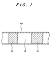
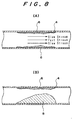
- the controller applies the pressure feeding of air to the recording head 52 for 30 seconds, and as shown in Fig. 1, the amount 10 of the cleaning liquid in the tube 53 between the nozzle of the three-way electromagnetic valve 56 and the recording head 52 and the filter and the recording head 52 is pushed out with the amount 12 of air.
- the controller causes the recording head 52 to shift to a position immediately above the wiping device 2 and performs the wiping of the bottom portion of the recording head 52 namely, performing the wiping operation (step 5).
- the controller applies the pressure feeding of the cleaning liquid to the recording head 52 for 20 seconds and fills the inside of the recording head 52 again with air (step 6).
- the foregoing operations are carried out for each of the recording heads 52 by the controller.
- the recording heads 52 are cleaned subsequently one after the other.
- the controller recovers (step 7) the liquid accumulated in a collecting pipe 120 by setting a waste liquid tank 118 in the negative pressure for 5 seconds.
- the controller releases the cleaning liquid tank 62 to the atmosphere, and cancels the application of the pressure to the cleaning liquid tank 62.
- the pressure feeding of air and cleaning liquid is alternately repeated twice preferably at an interval of 20 seconds or 30 seconds. If the pressure feeding of air and cleaning liquid is repeated for example 10 times alternately preferably at intervals of 5 seconds, the remaining ink in the ink passage between the three-way electromagnetic valves 56 and the recording heads 52 can be discharged, even more effectively.
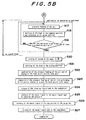
- the controller of the printer judges (step 1) on the basis of the signal of the sensor 138 as to whether there is any remaining quantity in the cleaning liquid tank 62 or not, and in case that the remaining quantity is nill or not enough, performs a processing for error (step 3) by displaying (step 2) the remaining quantity being none in the cleaning liquid tank on a display unit (illustration is omitted) of the operation panel of the printer.
- step 4 pressure is applied to the cleaning liquid tank 62 (step 4) by feeding air to the cleaning liquid tank 62, and pressure is applied (step 5) to the inside of the cleaning liquid tank 62 at a high level.
- the operation of the pressure application changes over the electromagnetic valves 72, 74, 76 between the pump and the main tank in the condition where the electromagnetic valve 78 is closed in the direction of the cleaning liquid tank, and drives the pump 66 and feeds air into the cleaning liquid tank 62.
- step 6 shifts (step 6) the respective recording head 52 as shown in Fig. 6 to a position immediately above the discharge outlet 110 of the purge box 106, namely, the purge position.
- Fig. 6 illustrates only one of the recording heads 52 among the four recording heads 52 for convenience of description, and displays a part of the purge box 106.
- the controller opens the electromagnetic valve 78 and changes over the electromagnetic valve 88 and the electromagnetic valve 56 of the recording head 52 of the first row which is the subject in the direction of the cleaning liquid tank, and performs the pressure feeding (step 7) of cleaning liquid at a high pressure for about 5 seconds to the nozzle of the recording head 52 and the corresponding tube 53 which are the subjects while driving the nozzle drive actuator (piezo element) of the recording head 52 at high speed with a frequency of preferably about 1 kHz.
- the controller closes the electromagnetic valve 78 and changes over the head air electromagnetic valves 74, 88 in the direction of the air feeding, and changes over the electromagnetic valve 56 of the recording head 52 that is the subject in the direction of the air feeding and applies the pressure feeding (step 8) of air at high pressure for about 10 seconds to the nozzle of the recording head 52 and the corresponding tube 53 which are the subjects while driving the nozzle drive actuator of the recording head 52 at a high speed with a frequency of preferably about 1 kHz.
- the remaining ink in the pipe wall of the ink passage between the inside of the recording head 52 and the tube 53 is peeled off and is pushed out in the ink passage and is discharged from the nozzle by the alternate pressure feeding operation of the high pressure cleaning liquid feeding and the high pressure air feeding.
- the controller judges (step 9) whether or not the alternate pressure feeding operation of the high pressure cleaning liquid feeding and the high pressure air feeding to the subject recording head 52 is carried out by a predetermined number of times (in this embodiment, once) and in case if the operation is not carried out by the predetermined number of times, it returns to the step 7, and if the operation is carried out by the predetermined number of times, it positions (step 10) the subject recording head 52 to a position immediately above the cap 108 of the purge box 106 namely the capping position.
- the controller performs the pressure feeding of air for about 10 seconds to the subject recording head 52 and executes (step 11) the cleaning of the cap portion by blowing the air from the nozzle of the recording head 52.
- the controller returns (step 12) the subject recording head 52 to the purge position.
- the controller performs the alternate pressure feeding operation of the high pressure feeding (step 13) of the cleaning liquid for about 5 seconds while driving at high speed the nozzle drive actuator of the recording head with a frequency of preferably about 1 kHz and thereafter, of the air high pressure feeding (step 14) for about 10 seconds.
- the remaining ink in the subject recording head 52 and the tube 53 is pushed to flow by the pressure feeding operation.
- the controller judges (step 15) whether or not the alternate pressure feeding operation of the high pressure cleaning liquid feeding and the high pressure air feeding to the subject recording head 52 is carried out by the predetermined number of times (in this embodiment, once) and when it is judged negative, it returns to the step 13, and if it is judged affirmative, the operations of the step 13 and the step 14 to the subject recording head 52 are completed.
- the operations of the steps 13, 14, 15 for each of the four pieces of the recording head 52 are carried out, and when the high pressure feeding operation of the steps 13, 14, 15 to all the recording heads 52 is completed, the controller sets the waste liquid tank 118 at negative pressure and recovers (step 16) the waste liquid such as the cleaning liquid accumulated in the collecting pipe 120 in the waste liquid tank 118.
- the controller performs (step 17) the pressure feeding of the air of high pressure to the subject one recording head 52 or about 40 seconds, and then, shifts the recording head 52 to the capping position, and returns (step 18) the recording head 52 to the purge position.
- This operation is executed for each of the four recording heads 52 of KMCY.
- the recording head 52 shifts from the purge position to the capping position and returns to the purge position instantly whereby the liquid droplet mixed with the ink that remains on the lower surface of the recording head is thrown off by the inertia of the recording head 52, and this liquid droplet drops to the liquid discharge outlet 110 of the purge box 106 or the receiving opening of the cap 108 and is stored in the collecting pipe 120.
- the controller judges (step 19) whether or not the liquid droplet shaking operation is carried out by the predetermined number of times (in this embodiment, twice) for each of the four pieces of the recording head 52, and when it is judged negative, it returns to the step 17 and when it is judged affirmative, the controller turns the vacuum device (illustration is omitted) for generating the suction power on the platen 34 ON, and causes the paper to adhere (step 20) to the platen 34.
- the predetermined number of times in this embodiment, twice
- the controller shifts (step 21) the recording head 52 to a position immediately above the wiping device 2 namely, the wiping position.
- the controller performs the pressure feeding of the air to the subject recording head 52 and drives the wiper motor 102 while blowing the air from the nozzle of the recording head 52, and shifts the rubber made wiper in one direction of one-way, and wipes (step 22) the nozzle portion of the subject recording head 52 with the wiper.
- the controller suspends the air pressure feeding to the subject recording head 52.
- the controller slides the recording head 52 slightly to the wiper and reciprocates the wiper to the subject recording head 52 by the drive of the motor 102, and performs the wiping (step 23) of the peripheral portion of the nozzle excluding the nozzle of the subject recording head 52 with the wiper.
- the controller performs the wiping operation on each of the KMCY recording heads 52.
- the controller changes over the electromagnetic valve 76 to the atmosphere side, and releases (step 24) the cleaning liquid tank 62 to the atmosphere.
- the controller reduces the pressure in the waste liquid tank 118 and recovers (step 25) the waste liquid to the waste liquid tank 118, and recovers (step 26) the waste liquid of the cap portion of the purge box 106.
- the controller changes over the electromagnetic valve 101 to the atmosphere side, and releases (step 27) the waste liquid tank 118 to the atmosphere, and completes the cleaning operation of the recording head 52.
- the release of the main tank 54 to the atmosphere is not executed. The reason for this is that the high pressure cleaning liquid or the high pressure air does not counterflow to the tube of the side of the sub-tank 54 at the changeover time of the head-sub-tank electromagnetic valve 56.
- the high pressure feeding of the cleaning liquid and the air is carried out while driving the piezo element that is the nozzle drive actuator of the recording head as described in the foregoing, but the embodiment is not particularly limited to the pressure feeding conducted while driving the piezo element with the high frequency drive signal.
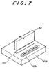
- the recording head 52 is caused to shift between the purge position and the capping position in order to shake off any liquid droplet adhered to the under surface of the recording head 52 but the operation of shaking off the liquid droplet is not limited particularly to the foregoing embodiment, and as shown in Fig. 7, the recording head 52 may be vibrated at the purge position, and the liquid droplet may be dropped to the liquid discharge outlet 110.
- cleaning liquid and air are arranged to be pressure fed alternately to the recording head so that the ink in the recording head and the tube can be effectively peeled off and can be pushed to flow to the outside. For this reason, the consuming quantity of the cleaning liquid is minimized, and the economy is extremely high. Furthermore, during the cleaning, since the operation of vibrating the recording head is set up, any liquid droplet mixed with the ink at the bottom surface of the recording head can be positively dropped to the required location, giving no chance for staining the periphery of the purge box.
- the present invention can effectively clean the ink passage including the inside of the recording head.
Applications Claiming Priority (4)
| Application Number | Priority Date | Filing Date | Title |
|---|---|---|---|
| JP20859299A JP2001030515A (ja) | 1999-07-23 | 1999-07-23 | インクジェットプリンタにおける洗浄装置 |
| JP20859299 | 1999-07-23 | ||
| JP2000155245 | 2000-05-25 | ||
| JP2000155245A JP2001334683A (ja) | 2000-05-25 | 2000-05-25 | インクジェットプリンタ |
Publications (1)
| Publication Number | Publication Date |
|---|---|
| EP1070592A1 true EP1070592A1 (fr) | 2001-01-24 |
Family
ID=26516915
Family Applications (1)
| Application Number | Title | Priority Date | Filing Date |
|---|---|---|---|
| EP00115461A Withdrawn EP1070592A1 (fr) | 1999-07-23 | 2000-07-18 | Imprimante à jet d'encre et procédé de son opération |
Country Status (2)
| Country | Link |
|---|---|
| EP (1) | EP1070592A1 (fr) |
| KR (1) | KR20010015416A (fr) |
Cited By (12)
| Publication number | Priority date | Publication date | Assignee | Title |
|---|---|---|---|---|
| GB2375738A (en) * | 2001-05-24 | 2002-11-27 | Sii Printek Inc | Ink jet printer including a liquid flow path supplying cleaning liquid to an ink jet head via a route separate from an ink flow path supplying ink to the head |
| EP1359027A3 (fr) * | 2002-04-30 | 2004-10-20 | Hewlett-Packard Company | Techniques de distribution de fluide avec fiabilité améliorée |
| WO2005108096A1 (fr) * | 2004-05-05 | 2005-11-17 | Eastman Kodak Company | Procede d'arret de la tete d'imprimante a jet d'encre |
| EP1621348A1 (fr) * | 2004-07-22 | 2006-02-01 | Toshiba Tec Kabushiki Kaisha | Solution de lavage pour une tête imprimante à jet d'encre et procédé de lavage utilisant la solution |
| WO2006084614A2 (fr) * | 2005-02-08 | 2006-08-17 | Durst Phototechnik - A.G. | Dispositif d'impression a jet d'encre et procede d'impression d'images multicolores |
| US7108367B2 (en) | 2002-04-24 | 2006-09-19 | Toshiba Tec Kabushiki Kaisha | Liquid ink and recording apparatus |
| EP1832428A1 (fr) * | 2004-12-22 | 2007-09-12 | Seiko Epson Corporation | Appareil de collecte de liquide use, relais et appareil d'injection de liquide |
| US7285581B2 (en) | 2003-06-18 | 2007-10-23 | Toshiba Tec Kabushiki Kaisha | Processed pigments, pigment-dispersed solution, ink for ink jet, manufacturing method of processed pigments and manufacturing method of pigment-dispersed solution |
| WO2007147273A1 (fr) * | 2006-06-23 | 2007-12-27 | Zünd Systemtechnik Ag | Système de têtes d'impression pour imprimante à jet d'encre |
| US7375145B2 (en) | 2003-10-28 | 2008-05-20 | Toshiba Tec Kabushiki Kaisha | Inkjet ink |
| US7439281B2 (en) | 2003-10-28 | 2008-10-21 | Toshiba Tec Kabushiki Kaisha | Pigment dispersion, precursor of ink for UV-curing type ink-jet recording, method of ink-jet recording, printed matter, and method of manufacturing pigment dispersion |
| EP2233295A1 (fr) * | 2009-03-27 | 2010-09-29 | Brother Kogyo Kabushiki Kaisha | Unité de nettoyage, appareil d'impression et procédé pour nettoyer un appareil d'impression |
Citations (4)
| Publication number | Priority date | Publication date | Assignee | Title |
|---|---|---|---|---|
| US4296418A (en) * | 1979-05-26 | 1981-10-20 | Ricoh Company, Ltd. | Ink jet printing apparatus with reverse solvent flushing means |
| WO1993017867A1 (fr) * | 1992-03-12 | 1993-09-16 | Willett International Limited | Procede de rinçage d'un systeme a circulation d'encre |
| US5543827A (en) * | 1994-04-11 | 1996-08-06 | Fas-Co Coders, Inc. | Ink jet print head nozzle cleaning coinciding with nozzle vibration |
| US5786829A (en) * | 1996-07-01 | 1998-07-28 | Xerox Corporation | Apparatus and method for cleaning an ink flow path of an ink jet printhead |
-
2000
- 2000-07-18 EP EP00115461A patent/EP1070592A1/fr not_active Withdrawn
- 2000-07-22 KR KR1020000042218A patent/KR20010015416A/ko not_active Application Discontinuation
Patent Citations (4)
| Publication number | Priority date | Publication date | Assignee | Title |
|---|---|---|---|---|
| US4296418A (en) * | 1979-05-26 | 1981-10-20 | Ricoh Company, Ltd. | Ink jet printing apparatus with reverse solvent flushing means |
| WO1993017867A1 (fr) * | 1992-03-12 | 1993-09-16 | Willett International Limited | Procede de rinçage d'un systeme a circulation d'encre |
| US5543827A (en) * | 1994-04-11 | 1996-08-06 | Fas-Co Coders, Inc. | Ink jet print head nozzle cleaning coinciding with nozzle vibration |
| US5786829A (en) * | 1996-07-01 | 1998-07-28 | Xerox Corporation | Apparatus and method for cleaning an ink flow path of an ink jet printhead |
Cited By (27)
| Publication number | Priority date | Publication date | Assignee | Title |
|---|---|---|---|---|
| GB2375738A (en) * | 2001-05-24 | 2002-11-27 | Sii Printek Inc | Ink jet printer including a liquid flow path supplying cleaning liquid to an ink jet head via a route separate from an ink flow path supplying ink to the head |
| US7500745B2 (en) | 2002-04-24 | 2009-03-10 | Toshiba Tec Kabushiki Kaisha | Liquid ink and recording apparatus |
| US7108367B2 (en) | 2002-04-24 | 2006-09-19 | Toshiba Tec Kabushiki Kaisha | Liquid ink and recording apparatus |
| US7125112B2 (en) | 2002-04-24 | 2006-10-24 | Toshiba Tec Kabushiki Kaisha | Liquid ink and recording apparatus |
| US7387380B2 (en) | 2002-04-24 | 2008-06-17 | Toshiba Tec Kabushiki Kaisha | Liquid ink and recording apparatus |
| EP1359027A3 (fr) * | 2002-04-30 | 2004-10-20 | Hewlett-Packard Company | Techniques de distribution de fluide avec fiabilité améliorée |
| EP1621352A3 (fr) * | 2002-04-30 | 2008-07-30 | Hewlett-Packard Company, A Delaware Corporation | Techniques de distribution de fluide avec fiabilité améliorée |
| US7285581B2 (en) | 2003-06-18 | 2007-10-23 | Toshiba Tec Kabushiki Kaisha | Processed pigments, pigment-dispersed solution, ink for ink jet, manufacturing method of processed pigments and manufacturing method of pigment-dispersed solution |
| US7439281B2 (en) | 2003-10-28 | 2008-10-21 | Toshiba Tec Kabushiki Kaisha | Pigment dispersion, precursor of ink for UV-curing type ink-jet recording, method of ink-jet recording, printed matter, and method of manufacturing pigment dispersion |
| US7473720B2 (en) | 2003-10-28 | 2009-01-06 | Toshiba Tec Kabushiki Kaisha | Photosensitive inkjet ink |
| US7754785B2 (en) | 2003-10-28 | 2010-07-13 | Toshiba Tec Kabushiki Kaisha | Pigment dispersion, precursor of ink for UV-curing type ink-jet recording, method of ink-jet recording, printed matter, and method of manufacturing pigment dispersion |
| US7375145B2 (en) | 2003-10-28 | 2008-05-20 | Toshiba Tec Kabushiki Kaisha | Inkjet ink |
| US7213902B2 (en) | 2004-05-05 | 2007-05-08 | Eastman Kodak Company | Method of shutting down a continuous ink jet printer for maintaining positive pressure at the printhead |
| WO2005108096A1 (fr) * | 2004-05-05 | 2005-11-17 | Eastman Kodak Company | Procede d'arret de la tete d'imprimante a jet d'encre |
| US7425525B2 (en) | 2004-07-22 | 2008-09-16 | Toshiba Tec Kabushiki Kaisha | Washing solution for inkjet printer head and washing method using the solution |
| CN100404261C (zh) * | 2004-07-22 | 2008-07-23 | 东芝泰格有限公司 | 喷墨打印机打印头用清洁溶液及使用该溶液的清洗方法 |
| EP1621348A1 (fr) * | 2004-07-22 | 2006-02-01 | Toshiba Tec Kabushiki Kaisha | Solution de lavage pour une tête imprimante à jet d'encre et procédé de lavage utilisant la solution |
| EP1832428A1 (fr) * | 2004-12-22 | 2007-09-12 | Seiko Epson Corporation | Appareil de collecte de liquide use, relais et appareil d'injection de liquide |
| EP1832428A4 (fr) * | 2004-12-22 | 2008-02-27 | Seiko Epson Corp | Appareil de collecte de liquide use, relais et appareil d'injection de liquide |
| US7726773B2 (en) | 2004-12-22 | 2010-06-01 | Seiko Epson Corporation | Waste liquid recovery apparatus, relay and liquid jetting apparatus |
| WO2006084614A2 (fr) * | 2005-02-08 | 2006-08-17 | Durst Phototechnik - A.G. | Dispositif d'impression a jet d'encre et procede d'impression d'images multicolores |
| WO2006084614A3 (fr) * | 2005-02-08 | 2006-11-30 | Durst Phototechnik Ag | Dispositif d'impression a jet d'encre et procede d'impression d'images multicolores |
| US8141981B2 (en) | 2005-02-08 | 2012-03-27 | Durst Phototechnik - A.G. | Inkjet printing device and method for printing multi-coloured images |
| US8764148B2 (en) | 2005-02-08 | 2014-07-01 | Durst Phototechnik—A.G. | Inkjet printing device and method for printing multi-colored images |
| WO2007147273A1 (fr) * | 2006-06-23 | 2007-12-27 | Zünd Systemtechnik Ag | Système de têtes d'impression pour imprimante à jet d'encre |
| EP2233295A1 (fr) * | 2009-03-27 | 2010-09-29 | Brother Kogyo Kabushiki Kaisha | Unité de nettoyage, appareil d'impression et procédé pour nettoyer un appareil d'impression |
| US8297732B2 (en) | 2009-03-27 | 2012-10-30 | Brother Kogyo Kabushiki Kaisha | Printing apparatus and cleaner unit for cleaning inkjet head and ink conveyer tube |
Also Published As
| Publication number | Publication date |
|---|---|
| KR20010015416A (ko) | 2001-02-26 |
Similar Documents
| Publication | Publication Date | Title |
|---|---|---|
| EP1033252B1 (fr) | Imprimante à jet d'encre et méthode pour son opération | |
| US6619783B2 (en) | Flushing position controller incorporated in ink-jet recording apparatus and flushing method used for the same | |
| US6561637B2 (en) | Ink jet head having buffer tank in fluid communication with ink circulation pathway | |
| US4571601A (en) | Ink jet printer having an eccentric head guide shaft for cleaning and sealing nozzle surface | |
| US6631974B2 (en) | Ink jet recording apparatus having wiping mechanism | |
| EP1354707B1 (fr) | Appareil de nettoyage pour tête d'impression à jets d'encre | |
| EP1070592A1 (fr) | Imprimante à jet d'encre et procédé de son opération | |
| JP2019136956A (ja) | 液体噴射装置、液体噴射装置のメンテナンス方法 | |
| JP2001334684A (ja) | インクジェットプリンタ | |
| JP2001030514A (ja) | インクジェットプリンタ | |
| JP2010058473A (ja) | ヘッドクリーニング装置及びこれを用いた画像形成装置 | |
| JP2010105310A (ja) | 液体噴射装置 | |
| JP2871023B2 (ja) | インクジェットヘッドのクリーニング装置 | |
| JP2001334685A (ja) | インクジェットプリンタ | |
| JP4421702B2 (ja) | インクジェットプリンタ | |
| EP1982836A2 (fr) | Commande de position de rinçage incorporé dans un appareil d'enregistrement à jet d'encre et méthode de rinçage utilisé à cet effet | |
| JP2001225478A (ja) | インクジェットプリンタ | |
| JPH1044447A (ja) | インクジェットヘッドのメンテナンス装置 | |
| JP4536858B2 (ja) | インクジェットプリンタ | |
| JP4408485B2 (ja) | インクジェットプリンタにおけるワイピング装置 | |
| JP2001030515A (ja) | インクジェットプリンタにおける洗浄装置 | |
| JP2001030505A (ja) | インクジェットプリンタ | |
| JP2001334683A (ja) | インクジェットプリンタ | |
| JPH11221927A (ja) | インクジェットプリンタのワイピング機構 | |
| JP2003001836A (ja) | ヘッド吐出特性維持装置及びそれを備えた記録装置 |
Legal Events
| Date | Code | Title | Description |
|---|---|---|---|
| PUAI | Public reference made under article 153(3) epc to a published international application that has entered the european phase |
Free format text: ORIGINAL CODE: 0009012 |
|
| AK | Designated contracting states |
Kind code of ref document: A1 Designated state(s): BE DE ES FR GB IT |
|
| AX | Request for extension of the european patent |
Free format text: AL;LT;LV;MK;RO;SI |
|
| 17P | Request for examination filed |
Effective date: 20010517 |
|
| AKX | Designation fees paid |
Free format text: BE DE ES FR GB IT |
|
| STAA | Information on the status of an ep patent application or granted ep patent |
Free format text: STATUS: THE APPLICATION IS DEEMED TO BE WITHDRAWN |
|
| 18D | Application deemed to be withdrawn |
Effective date: 20030201 |