EP1070540A2 - Flüssigkeitsspender - Google Patents
Flüssigkeitsspender Download PDFInfo
- Publication number
- EP1070540A2 EP1070540A2 EP00306061A EP00306061A EP1070540A2 EP 1070540 A2 EP1070540 A2 EP 1070540A2 EP 00306061 A EP00306061 A EP 00306061A EP 00306061 A EP00306061 A EP 00306061A EP 1070540 A2 EP1070540 A2 EP 1070540A2
- Authority
- EP
- European Patent Office
- Prior art keywords
- nozzles
- nozzle holder
- cylinders
- plate
- dispensing
- Prior art date
- Legal status (The legal status is an assumption and is not a legal conclusion. Google has not performed a legal analysis and makes no representation as to the accuracy of the status listed.)
- Granted
Links
Images


Classifications
-
- G—PHYSICS
- G01—MEASURING; TESTING
- G01N—INVESTIGATING OR ANALYSING MATERIALS BY DETERMINING THEIR CHEMICAL OR PHYSICAL PROPERTIES
- G01N35/00—Automatic analysis not limited to methods or materials provided for in any single one of groups G01N1/00 - G01N33/00; Handling materials therefor
- G01N35/10—Devices for transferring samples or any liquids to, in, or from, the analysis apparatus, e.g. suction devices, injection devices
- G01N35/1065—Multiple transfer devices
-
- B—PERFORMING OPERATIONS; TRANSPORTING
- B01—PHYSICAL OR CHEMICAL PROCESSES OR APPARATUS IN GENERAL
- B01L—CHEMICAL OR PHYSICAL LABORATORY APPARATUS FOR GENERAL USE
- B01L3/00—Containers or dishes for laboratory use, e.g. laboratory glassware; Droppers
- B01L3/02—Burettes; Pipettes
- B01L3/021—Pipettes, i.e. with only one conduit for withdrawing and redistributing liquids
- B01L3/0217—Pipettes, i.e. with only one conduit for withdrawing and redistributing liquids of the plunger pump type
-
- B—PERFORMING OPERATIONS; TRANSPORTING
- B01—PHYSICAL OR CHEMICAL PROCESSES OR APPARATUS IN GENERAL
- B01L—CHEMICAL OR PHYSICAL LABORATORY APPARATUS FOR GENERAL USE
- B01L3/00—Containers or dishes for laboratory use, e.g. laboratory glassware; Droppers
- B01L3/02—Burettes; Pipettes
- B01L3/0275—Interchangeable or disposable dispensing tips
- B01L3/0279—Interchangeable or disposable dispensing tips co-operating with positive ejection means
-
- G—PHYSICS
- G01—MEASURING; TESTING
- G01N—INVESTIGATING OR ANALYSING MATERIALS BY DETERMINING THEIR CHEMICAL OR PHYSICAL PROPERTIES
- G01N35/00—Automatic analysis not limited to methods or materials provided for in any single one of groups G01N1/00 - G01N33/00; Handling materials therefor
- G01N35/10—Devices for transferring samples or any liquids to, in, or from, the analysis apparatus, e.g. suction devices, injection devices
- G01N2035/1027—General features of the devices
- G01N2035/103—General features of the devices using disposable tips
-
- Y—GENERAL TAGGING OF NEW TECHNOLOGICAL DEVELOPMENTS; GENERAL TAGGING OF CROSS-SECTIONAL TECHNOLOGIES SPANNING OVER SEVERAL SECTIONS OF THE IPC; TECHNICAL SUBJECTS COVERED BY FORMER USPC CROSS-REFERENCE ART COLLECTIONS [XRACs] AND DIGESTS
- Y10—TECHNICAL SUBJECTS COVERED BY FORMER USPC
- Y10T—TECHNICAL SUBJECTS COVERED BY FORMER US CLASSIFICATION
- Y10T436/00—Chemistry: analytical and immunological testing
- Y10T436/25—Chemistry: analytical and immunological testing including sample preparation
- Y10T436/2575—Volumetric liquid transfer
Definitions
- This invention relates to a liquid dispenser for liquid reagents, liquid samples and the like and, more specifically, to a holder-exchanger of such a dispenser for holding or replacing its dispensing tips.
- liquid blood, sample, reagent, or other object to be tested
- wells cuvettes, or other small containers
- Prior art liquid dispensers generally comprise a horizontal base and a housing frame of upright support.
- the horizontal base carries an X stage movable in the X direction, and the X stage supports thereon a Y stage movable in the Y direction.
- the Y stage in turn carries, by means of a frame plate, a tip rack having an array of holes (in 8 rows and 12 columns) arranged in order to hold a number of tips, at least one plate having holes to support a number of wells in an equidistantly spaced arrangement of the same number, and a reagent or wash tank holding a reagent or wash as the case may be.
- the X and Y stages can be driven independently of each other by an X-axis drive motor or Y-axis drive motor at a command from a control console.
- the upright support supports a Z-axis-movable dispensing head, which carries plungers and cylinders in the same numbers and at the same intervals as the holes of the tip rack and plate. Tips (usually either type, although two types are shown here) are fitted to nozzles that constitute the lower ends of the cylinders.
- the dispensing head is driven as a whole in the Z-axis direction by a Z-axis drive motor, and the plungers are driven by an S-axis motor.
- the X and Y stages are first driven to align the tip rack to the nozzles of the cylinders, the dispensing head is lowered in the Z-axis direction until the nozzle tips are fitted airtightly in the bores at the upper ends of dispensing tips so that all the tips are held by the nozzles, and then the dispensing head is moved up.
- the reagent tank is aligned just below the nozzles holding the tips, the dispensing head is lowered, bringing the lower ends of the dispensing tips into the reagent tank, the plungers are moved upward to draw by suction predetermined amounts of the reagent, and thus the dispensing head is raised.
- the plate is brought in place under the nozzles holding the dispensing tips, the dispensing head is lowered to position the tips immediately above the wells containing the sample (blood or the like). Finally, the plungers are forced downward to dispense the reagent into the sample wells.
- the nozzles of the prior art constitute the lower ends of the cylinders, and the combinations of many cylinders and plungers arranged in an orderly manner are supported by a single supporting block.
- the amount to be dispensed depends on the size of the tips, and the outside diameter of the nozzles to fit in the holes at the ends of the tips must be changed in accordance with the dispensing amount.
- the invention provides a liquid dispenser characterized by a dispensing head which is movable upward and downward as a whole and comprises a plurality of plungers supported by a plunger plate, drive means for moving the plunger plate upward and downward, a plurality of cylinders in which the plungers slidably fit, and a plurality of nozzles arranged at the lower ends of the cylinders and having configurations adapted to engage airtightly with holes for holding specific dispensing tips, the plurality of nozzles being supported by a single nozzle holder, which is built to be detachable from said dispensing head.
- nozzle holder that support nozzles has to be replaced with another holder conforming to dispensing tips of different dimensions.
- the arrangement may facilitate the replacement and make the dispenser available at lower cost.
- An advantage of the preferred embodiment of the present invention is that it solves the problems of the prior art by providing a dispenser in which nozzles are separated from cylinders and are supported by a common block as a nozzle block which alone can be replaced with another one when the necessity arises.
- the nozzles preferably have an annular extended head each and are loosely fitted in the support block, simply as inserted from above into the block. They may be fitted in the holes at the upper ends of the dispensing tips by self-aligning and thereby achieve positive airtight engagement with the tips.
- an elastic seal plate such as of silicone rubber having openings aligned to the bores of the nozzles and cylinders is sandwiched between the upper surface of the nozzle holder and the plunger-cylinder block, whereby airtight fluid communication is easily established between the nozzles and cylinders.
- the means for attaching and detaching the nozzle holder in a predetermined point comprises vertical clamp plates having clamps adapted to be engaged with lower edges of the nozzle holder, may further include elastic members that normally bias the clamp plates upward, and may also include means for pressing the clamp plates downward against the urgings of the elastic members.
- the means for pressing the clamp plates downward may be a plunger plate and means for driving it.
- an eject plate is located under the nozzle holder to remove all dispensing tips simultaneously from the nozzles.
- the eject plate may have a plurality of holes to allow the nozzles to extend through them with tip-fitting ends of the nozzles protruding beyond the bottom of the eject plate.
- the diameter of the holes of the eject plate may be smaller than the outside diameter of the upper ends of the dispensing tips.
- the eject plate when forced downward by the bottom surfaces of the clamps of clamp plates, can simultaneously release and remove all tips simultaneously from the nozzles.
- the plate may be normally biased toward the nozzle plates by springs provided on the nozzle holder.
- the eject plate may be pressed downward by means other than the clamp plates.
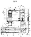
- Figs. 1 to 3 illustrate the general construction of a liquid dispenser embodying the invention, which is characterized by a dispensing head 19 having a mechanism for holding and replacing dispensing tips.
- Figs. 4 to 6 are enlarged views of the dispensing head 19. Essential parts of the head 19 are shown in Figs. 7 and 8.
- Fig. 1 is a front view of the liquid dispenser
- Fig. 2 is a side view
- Fig. 3 is a plan view of a stage assembly.
- the liquid dispenser includes a horizontal base 1 and a housing frame of upright support 2.
- the horizontal base 1 carries an X stage 3 which is made movable in the X direction by X-axis linear guides 37, and the X stage 3 supports thereon a Y stage 5 which is made movable in the Y direction by Y-axis linear guides 39 mounted on the X stage.
- the Y stage 5 carries thereon a frame plate 7 detachably secured in place with frame guide pins 8.
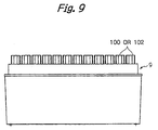
- the frame plate 7 in turn carries a tip rack 9 (see FIG.
- the X stage 3 is driven in the X-axis direction, in response to a control signal received from a control console through a controller 35, by an X-axis drive motor 15 with a pulley 31 and a timing belt 33.
- the Y stage 5 is driven independently of the X stage, in response to a control signal from the control console through the controller 35, by a Y-axis drive motor 17 with a pulley.
- the position of the X stage 3 is detected by an X-axis sensor 51.
- a Y-axis sensor (not shown) functions likewise.
- the upright support 2 holds up a dispensing head 19 movably in the Z-axis direction.
- the dispensing head 19 has a frame 18 supported by a pair of linear bearings 53 vertically spaced apart and arranged in tandem.
- the linear bearings 53 are slidably guided in the Z-axis (vertical) direction by a pair of shaft-retaining plates 57 (only the upper one is shown) which too are vertically spaced apart and secured in tandem to the upright support 2.
- a Z-axis motor 27, mounted in the support frame 2 drives the linear bearings 53 in the Z-axis direction via a coupling 61 and a ball screw 63 retained in position by a bearing 55.
- FIG. 4 is a front view
- FIG. 5 is a right side view with the omission of a vertical bracket 65
- FIG. 6 is a right side view with the bracket 65.
- a cylinder block 67 is secured with clamps 69 to the frame 18 of the dispensing head 19.
- vertical brackets 65 are supported by a horizontal bracket 77 fixed to the frame 18.
- the cylinder block 67 comprises two side blocks 71 and upper and lower blocks 73, 75 having am array of openings in a regular pattern to receive and support cylinders 23.
- the upper block 73 supports the upper ends of the cylinders 23 and the lower block 75 supports the lower ends.
- S axis as used herein means the axis for motion in the vertical direction, as distinguished from the Z axis.
- the frame 18 also carries the horizontal bracket 77, which in turn supports a vertical rotating shaft 83 through bearings 81.
- the shaft is caused to rotate by the S-axis motor 79 through a pulley 85, timing belt 84, and pulley 87.
- the rotating shaft 83 has a ball screw 89, which bears up a horizontal plunger plate 91.
- the ball screw 89 changes the rotation of the shaft to a movement in the S-axis (vertical) direction and moves the plunger plate 91 upward and downward.
- the plunger plate 91 is fixed to guide shafts 93, which slide along guides secured to the frame 18 and through guide holes formed in the cylinder block to guide the plunger plate 91 vertically.
- To the plunger plate 91 are fixed the upper ends of a number of plungers 21 that fit in corresponding bores of cylinders 23.
- the lower ends of the plungers 21 fit in the upper ends of the cylinders 23 and the both ends are airtightly joined with seals 95.
- the S-axis motor 79 is started and its power is transmitted through the pulley 85, timing belt 84, pulley 87, and rotating shaft 83 to rotate the ball screw 89, whereby the plunger plate 91 is driven downward or upward.
- the plungers 21 move into or out of the cylinders 23 a predetermined distance to draw a predetermined amount of air by suction or discharge it each. In this manner air can be introduced into or forced out of tips 100 or 102 by nozzles 101 so that a given liquid can be accurately dispensed in equal, predetermined amounts as will be explained in detail later.
- a nozzle holder 97 which has a number of holes supporting an array of (small) nozzles 99 or (large) nozzles 101, preferably fitting loosely, in an arrangement corresponding to the cylinders. Loosely received in the holes, the nozzles have allowances to move slightly for a proper airtight fit when their ends are engaged with the upper end openings of tips. In the absence of the allowances, some of the many tips could fail to fit properly and be left unengaged in the rack 9 (FIGS. 3 and 9).
- the nozzles 99 or 101 have an annular extended head each with which to be fitted in the holes of the nozzle holder 97.
- the nozzle holder 97 is urged by clamps 104 at the lower ends of clamp plates 103 against the bottom of the cylinder block 67, whereby the upper ends of the nozzles are forced in contact with the lower ends of the cylinders 23.
- an elastic plate such as silicone plate 109 is sandwiched between the nozzle holder 97 and the bottom of the cylinder block 67 to establish airtight communication between the cylinders 23 and the nozzles 99 or 101.
- Each clamp plate 103 is supported by the vertical bracket 65 which in turn is held by the horizontal bracket 77, in such manner that the clamp plate can slide vertically along the outer surface of the bracket.
- a pair of clamp plate guides 105 are fixed to the cylinder block 67 (FIG. 6), and the clamp plate 103 is formed with slots 111 in which the guides 105 fit.
- a plurality of tension springs 113 are secured at the upper ends to the bracket 65, and the lower ends of the springs 113 are secured to the upper end of the clamp plate 103.
- the clamp plate 103 is normally biased upward, forcing the nozzle holder 97 against the cylinder block 67 with the aid of the clamps 104 to provide desired airtight communication between the cylinders 23 and nozzles 99 or 101.
- the strength of the springs 113 can be controlled by adjusting the positions of screws 115.
- the nozzle holder 97 has stoppers 119 fixed to the four corners of its underside, all in contact with an eject plate 123.
- the eject plate 123 is elasticly pressed against the stoppers 119 by eject springs 125 held in place by spring pins 121.
- the plate has throughholes in which the nozzles 99 or 101 extend their lower portions to expose the ends on which tips are to be fitted.
- the lower ends of the throughholes are designed to be smaller in diameter than the upper ends of the tips 100 or 102.
- Means of pushing down the eject plate 123 may be provided separately, but preferably the clamp plates 103 as in the illustrated are utilized for that purpose too.
- the bottom surfaces of the clamps 104 at the lower ends of the clamp plate serve as surfaces to act on the eject plate 123.
- the clamp plates 103 are forced downward by the descent of the plunger plate 91 to release the nozzle holder 97.
- the nozzle holder 97 comes to rest on the holding bends 108 of the holder supports 107.
- a farther descent of the clamp plate causes the clamps 104 to fall past the holding bends 108 to the points shown in FIG. 8.
- the eject plate 123 then drops away from the stoppers 119 against the urgings of the springs 125, with the consequence that the tips drop off altogether. Subsequent ascent of the plunger plate permits the springs 125 to recover their elasticity to bring the eject plate 123 back to the original position, ready to receive new tips.
- the present invention makes it possible to manufacture a liquid dispenser at lower cost than heretofore. Since its plunger-cylinder combinations are made separate from nozzles, and the nozzles are supported by a detachable nozzle holder, not only tips of different sizes can be replaced with ease but also the plunger-cylinder combinations can be used with all sizes of nozzles.
- an elastic seal plate such as of silicone permits airtight coupling of cylinders and nozzle despite the separate nozzle design.
Landscapes
- Health & Medical Sciences (AREA)
- Chemical & Material Sciences (AREA)
- Clinical Laboratory Science (AREA)
- Chemical Kinetics & Catalysis (AREA)
- Analytical Chemistry (AREA)
- Life Sciences & Earth Sciences (AREA)
- Physics & Mathematics (AREA)
- Biochemistry (AREA)
- General Health & Medical Sciences (AREA)
- General Physics & Mathematics (AREA)
- Immunology (AREA)
- Pathology (AREA)
- Automatic Analysis And Handling Materials Therefor (AREA)
- Sampling And Sample Adjustment (AREA)
- Loading And Unloading Of Fuel Tanks Or Ships (AREA)
Applications Claiming Priority (2)
| Application Number | Priority Date | Filing Date | Title |
|---|---|---|---|
| JP11208875A JP2001033463A (ja) | 1999-07-23 | 1999-07-23 | 液体分注装置 |
| JP20887599 | 1999-07-23 |
Publications (3)
| Publication Number | Publication Date |
|---|---|
| EP1070540A2 true EP1070540A2 (de) | 2001-01-24 |
| EP1070540A3 EP1070540A3 (de) | 2002-06-26 |
| EP1070540B1 EP1070540B1 (de) | 2007-02-21 |
Family
ID=16563573
Family Applications (1)
| Application Number | Title | Priority Date | Filing Date |
|---|---|---|---|
| EP00306061A Expired - Lifetime EP1070540B1 (de) | 1999-07-23 | 2000-07-17 | Flüssigkeitsspender |
Country Status (4)
| Country | Link |
|---|---|
| US (1) | US6589483B1 (de) |
| EP (1) | EP1070540B1 (de) |
| JP (1) | JP2001033463A (de) |
| DE (1) | DE60033472D1 (de) |
Cited By (4)
| Publication number | Priority date | Publication date | Assignee | Title |
|---|---|---|---|---|
| WO2002102514A1 (en) * | 2001-06-19 | 2002-12-27 | B.C. Cancer Agency | Microvolume liquid dispenser suitable for microarrays and methods related thereto |
| US6589483B1 (en) | 1999-07-23 | 2003-07-08 | Cosmotec Co., Ltd | Liquid dispenser |
| US6982063B2 (en) | 2001-05-25 | 2006-01-03 | Matrix Technologies Corp | Automated pipetting system |
| EP2572786A1 (de) * | 2011-09-20 | 2013-03-27 | CyBio AG | Pipetiervorrichtung mit einem Pipetierkopf mit einer Vielzahl von in einem Anordnungsmuster angeordneten Pipetierkanälen |
Families Citing this family (50)
| Publication number | Priority date | Publication date | Assignee | Title |
|---|---|---|---|---|
| US20020142483A1 (en) | 2000-10-30 | 2002-10-03 | Sequenom, Inc. | Method and apparatus for delivery of submicroliter volumes onto a substrate |
| US6855538B2 (en) * | 2001-06-27 | 2005-02-15 | The Regents Of The University Of California | High-efficiency microarray printing device |
| US7402286B2 (en) * | 2001-06-27 | 2008-07-22 | The Regents Of The University Of California | Capillary pins for high-efficiency microarray printing device |
| US6846680B2 (en) * | 2001-07-31 | 2005-01-25 | Caliper Life Sciences, Inc. | Liquid handling system with automatically interchangeable cannula array |
| US20040141885A1 (en) * | 2002-02-12 | 2004-07-22 | Molecular Devices Corp. | Pipettor systems and components |
| US7144554B1 (en) * | 2002-08-02 | 2006-12-05 | Hamilton Company | Ultra low volume probe |
| JP3733942B2 (ja) * | 2002-10-03 | 2006-01-11 | 松下電器産業株式会社 | 分注装置および分注装置における分注ティップの離脱方法 |
| JP2005037179A (ja) * | 2003-07-17 | 2005-02-10 | Mitsubishi Kagaku Iatron Inc | カートリッジシールの穿孔具を備えた自動測定装置 |
| EP1753536B1 (de) * | 2004-05-10 | 2008-03-12 | Bernd Steinbrenner | Vorrichtung zur aufnahme und abgabe von flüssigkeiten |
| US20050265900A1 (en) * | 2004-05-27 | 2005-12-01 | Gard Douglas J | Pipetting system with selective pipette tip loading |
| DE102004057450B4 (de) * | 2004-11-24 | 2013-07-25 | Cybio Ag | Automatisches Pipetier- und Analysegerät |
| EP1884781B1 (de) * | 2005-05-17 | 2015-02-25 | Musashi Engineering, Inc. | Automatische hochgeschwindigkeitsabgabevorrichtung mit austauschbarem abgabekopf und abgabeplatz |
| WO2006132620A1 (en) * | 2005-06-03 | 2006-12-14 | Alfa Wassermann, Inc. | Fraction collector |
| FI118955B (fi) * | 2006-04-25 | 2008-05-30 | Biohit Oyj | Pipetin kärjen valintamenetelmä ja laite menetelmän toteuttamiseksi |
| JP4179338B2 (ja) * | 2006-05-22 | 2008-11-12 | 松下電器産業株式会社 | 分注装置 |
| JP4944526B2 (ja) * | 2006-07-19 | 2012-06-06 | 日立アロカメディカル株式会社 | ノズル装置 |
| US8012767B2 (en) * | 2006-08-07 | 2011-09-06 | Amgen Inc. | Pipette tip loading assembly |
| US7662344B2 (en) | 2006-10-24 | 2010-02-16 | Viaflo Corporation | Locking pipette tip and mounting shaft |
| JP4993094B2 (ja) * | 2007-06-12 | 2012-08-08 | メディカテック株式会社 | 分注機の吸引分注ヘッドにおけるピストンの組付方法 |
| US20090180931A1 (en) | 2007-09-17 | 2009-07-16 | Sequenom, Inc. | Integrated robotic sample transfer device |
| US20090104078A1 (en) * | 2007-10-18 | 2009-04-23 | Matrix Technologies Corporation | Apparatus and method for dispensing small volume liquid samples |
| JP5470369B2 (ja) | 2008-04-11 | 2014-04-16 | バイオティクス, インコーポレイテッド | ピペットチップを取り扱うデバイスおよび方法 |
| US20100089938A1 (en) * | 2008-04-11 | 2010-04-15 | Arta Motadel | Pipette tip handling devices and methods |
| JP2010181381A (ja) * | 2009-02-09 | 2010-08-19 | Tamagawa Seiki Co Ltd | 分注機における分注用チップ取外し機構 |
| US8590736B2 (en) * | 2009-04-11 | 2013-11-26 | Biotix, Inc. | Automated pipette tip loading devices and methods |
| USD697227S1 (en) | 2009-04-11 | 2014-01-07 | Biotix, Inc. | Pipette tip handling device set |
| USD699859S1 (en) | 2009-04-11 | 2014-02-18 | Biotix, Inc. | Pipette tip handling device assembly |
| USD673295S1 (en) | 2009-04-11 | 2012-12-25 | Biotix, Inc. | Automated pipette tip loading device set |
| USD673294S1 (en) | 2009-04-11 | 2012-12-25 | Biotix, Inc. | Pipette tip handling device component |
| EP2585834B1 (de) | 2010-06-28 | 2017-12-20 | Life Technologies Corporation | Systeme und verfahren zur übertragung von flüssigkeitsproben |
| US9696332B2 (en) * | 2010-07-23 | 2017-07-04 | Matrix Technologies Llc | Automated liquid handling device |
| JP2014508034A (ja) * | 2011-01-28 | 2014-04-03 | インテグラ バイオサイエンシズ コープ. | マルチチャンネルウェルプレート充填システム |
| EP2710385B1 (de) | 2011-05-20 | 2016-10-19 | PerkinElmer Health Sciences, Inc. | Liquid-handling-systeme sowie verfahren dafür |
| JP5643778B2 (ja) * | 2012-02-24 | 2014-12-17 | アルファ ワッサーマン インコーポレイテッドAlfa Wassermann,Inc. | フラクションコレクタ |
| WO2014071243A1 (en) * | 2012-11-02 | 2014-05-08 | Biotix, Inc. | Pipetting system device |
| US9868555B2 (en) * | 2014-04-28 | 2018-01-16 | Robert F. LiVolsi | Systems and methods for filling inoculations |
| NZ728582A (en) * | 2014-07-28 | 2020-06-26 | Douglas Scient Llc | Instrument for analyzing biological samples and reagents |
| CN105170210A (zh) * | 2015-10-14 | 2015-12-23 | 东南大学 | 一种多通道液体转移装置 |
| DE102016111912A1 (de) * | 2016-06-29 | 2018-01-04 | Eppendorf Ag | Dosierkopf, Dosiervorrichtung umfassend einen Dosierkopf und Verfahren zum Dosieren mittels eines Dosierkopfes |
| WO2018038019A1 (ja) * | 2016-08-22 | 2018-03-01 | ユニバーサル・バイオ・リサーチ株式会社 | 分注用シリンダ、並びに、それを用いた分注装置および分注処理方法 |
| CN110352343B (zh) * | 2016-11-18 | 2023-10-27 | 莫拉雷研究公司 | 生物样品制备系统和相关方法 |
| US10758909B2 (en) * | 2017-07-25 | 2020-09-01 | Thomas A. HEDGLIN | Device to assist in manual transfer of pipette tips |
| US11313872B2 (en) * | 2017-10-31 | 2022-04-26 | Hitachi High-Tech Corporation | Dispensing device and sample analysis device |
| ES2911471T3 (es) * | 2018-12-14 | 2022-05-19 | Eppendorf Ag | Aparato automático de laboratorio para el tratamiento automático de muestras de laboratorio |
| EP3693745B1 (de) * | 2019-02-07 | 2023-05-17 | Sartorius Biohit Liquid Handling Oy | Spitzenentfernung in einem automatisierten pipettenmodul |
| CN110823642A (zh) | 2019-11-09 | 2020-02-21 | 北京美联泰科生物技术有限公司 | 移液装置 |
| EP3832700A1 (de) * | 2019-12-03 | 2021-06-09 | Nexperia B.V. | Klebstoffabgabeeinheit |
| WO2022174178A2 (en) * | 2021-02-15 | 2022-08-18 | University Of South Florida | Systems and methods for dispensing liquids |
| KR102369417B1 (ko) * | 2021-08-20 | 2022-03-07 | 주식회사 에이블랩스 | 액체 핸들링 장치 |
| US12103220B2 (en) | 2022-03-28 | 2024-10-01 | Weiler Engineering, Inc. | Nozzle alignment fixture |
Family Cites Families (35)
| Publication number | Priority date | Publication date | Assignee | Title |
|---|---|---|---|---|
| US3568735A (en) * | 1968-06-26 | 1971-03-09 | Cooke Eng Co | Laboratory microtitration dispensing apparatus |
| US3650306A (en) * | 1970-09-18 | 1972-03-21 | Cooke Eng Co | Laboratory dispensing apparatus |
| FI52025C (fi) * | 1976-04-08 | 1977-06-10 | Osmo Antero Suovaniemi | Menetelmä ja laitteisto nesteannosteluun, nesteen siirtoon ja laimennu ssarjoihin. |
| US4158035A (en) * | 1978-03-15 | 1979-06-12 | Byrd William J | Multiple sample micropipette |
| US4444062A (en) * | 1982-05-05 | 1984-04-24 | Bennett John T | Liquid transfer device |
| NO862717L (no) * | 1985-07-05 | 1987-01-06 | Cetus Corp | Fremgangsmaate og apparat for automatisk vaeske-behandling. |
| US5104621A (en) | 1986-03-26 | 1992-04-14 | Beckman Instruments, Inc. | Automated multi-purpose analytical chemistry processing center and laboratory work station |
| US4824642A (en) | 1986-10-21 | 1989-04-25 | Costar Corporation | Multi-channel pipetter |
| US4779467A (en) * | 1987-01-28 | 1988-10-25 | Rainin Instrument Co., Inc. | Liquid-end assembly for multichannel air-displacement pipette |
| US5055263A (en) * | 1988-01-14 | 1991-10-08 | Cyberlab, Inc. | Automated pipetting system |
| US5061449A (en) | 1989-07-25 | 1991-10-29 | Matrix Technologies, Corp. | Expandable multi-channel pipetter |
| US5525302A (en) * | 1991-02-01 | 1996-06-11 | Astle; Thomas W. | Method and device for simultaneously transferring plural samples |
| US5827745A (en) * | 1993-03-29 | 1998-10-27 | Astle; Thomas W. | Micropipette tip loading and unloading device and method and tip package |
| US5439649A (en) * | 1993-09-29 | 1995-08-08 | Biogenex Laboratories | Automated staining apparatus |
| JP3260237B2 (ja) | 1994-03-07 | 2002-02-25 | 株式会社コスモテック | 液体分注装置 |
| US5470538A (en) * | 1994-06-03 | 1995-11-28 | Labcon, North America | Pipette tip rack loader |
| JP3481705B2 (ja) * | 1994-12-12 | 2003-12-22 | 株式会社モリテックス | 自動固相抽出装置 |
| US5497670A (en) * | 1995-03-31 | 1996-03-12 | Carl; Richard A. | Liquid dispensing apparatus including means for loading pipette tips onto liquid dispensing cylinders and maintaining the loading force during the apparatus operation cycle |
| JP3461618B2 (ja) | 1995-04-10 | 2003-10-27 | 株式会社コスモテック | 血液凝固時間測定方法及び装置 |
| US5772962A (en) * | 1995-05-29 | 1998-06-30 | Hitachi, Ltd. | Analyzing apparatus using disposable reaction vessels |
| US5642816A (en) * | 1995-10-25 | 1997-07-01 | Rainin Instrument Co., Inc. | Pipette tip rack refill plate hold down apparatus |
| US5915284A (en) * | 1996-07-22 | 1999-06-22 | Cyberlab, Inc. | Multiple channel pipetting device |
| US6116099A (en) * | 1996-11-18 | 2000-09-12 | Carl; Richard A. | Liquid dispensing apparatus having means for loading pipette tips onto fluid dispensing cylinders |
| JPH10263421A (ja) | 1997-03-21 | 1998-10-06 | Fukae Kasei Kk | 粉体分与用ディスポーザブルピペットチップと装置 |
| US6838051B2 (en) * | 1999-05-03 | 2005-01-04 | Ljl Biosystems, Inc. | Integrated sample-processing system |
| US6006800A (en) * | 1997-11-21 | 1999-12-28 | Nichiryo Co., Ltd. | Apparatus and method for automatic distribution |
| US6415669B1 (en) * | 1998-04-09 | 2002-07-09 | Ccs Packard, Inc. | Dispensing apparatus having means for loading pipette tips in a dispense head |
| JP3584732B2 (ja) * | 1998-05-08 | 2004-11-04 | 松下電器産業株式会社 | 分注装置および分注方法ならびに分注チップの装着方法 |
| US5988236A (en) * | 1998-07-31 | 1999-11-23 | Gilson, Inc. | Multiple syringe pump assembly for liquid handler |
| US6309891B1 (en) * | 1998-09-09 | 2001-10-30 | Incyte Genomics, Inc. | Capillary printing systems |
| US6132582A (en) * | 1998-09-14 | 2000-10-17 | The Perkin-Elmer Corporation | Sample handling system for a multi-channel capillary electrophoresis device |
| US6258324B1 (en) * | 1999-03-15 | 2001-07-10 | Felix H. Yiu | Pipette dispensing block |
| JP2001033463A (ja) | 1999-07-23 | 2001-02-09 | Cosmo Tec:Kk | 液体分注装置 |
| US6326212B1 (en) * | 1999-10-12 | 2001-12-04 | Arden Systems, Inc. | Membrane dispensing head apparatus and method for dispensing liquid |
| US6399024B1 (en) * | 2000-02-01 | 2002-06-04 | Incyte Genomics, Inc. | Multichannel pipette head |
-
1999
- 1999-07-23 JP JP11208875A patent/JP2001033463A/ja active Pending
-
2000
- 2000-07-17 EP EP00306061A patent/EP1070540B1/de not_active Expired - Lifetime
- 2000-07-17 DE DE60033472T patent/DE60033472D1/de not_active Expired - Lifetime
- 2000-07-21 US US09/621,497 patent/US6589483B1/en not_active Expired - Lifetime
Cited By (6)
| Publication number | Priority date | Publication date | Assignee | Title |
|---|---|---|---|---|
| US6589483B1 (en) | 1999-07-23 | 2003-07-08 | Cosmotec Co., Ltd | Liquid dispenser |
| US6982063B2 (en) | 2001-05-25 | 2006-01-03 | Matrix Technologies Corp | Automated pipetting system |
| WO2002102514A1 (en) * | 2001-06-19 | 2002-12-27 | B.C. Cancer Agency | Microvolume liquid dispenser suitable for microarrays and methods related thereto |
| EP2572786A1 (de) * | 2011-09-20 | 2013-03-27 | CyBio AG | Pipetiervorrichtung mit einem Pipetierkopf mit einer Vielzahl von in einem Anordnungsmuster angeordneten Pipetierkanälen |
| CN103008039A (zh) * | 2011-09-20 | 2013-04-03 | 西比欧公司 | 具备带多个排成一定格局的移液通道的移液头的移液装置 |
| US9084993B2 (en) | 2011-09-20 | 2015-07-21 | Analytik Jena Ag | Pipetting apparatus with a pipetting head comprising a multiplicity of pipetting channels disposed in an arrangement pattern |
Also Published As
| Publication number | Publication date |
|---|---|
| EP1070540A3 (de) | 2002-06-26 |
| JP2001033463A (ja) | 2001-02-09 |
| DE60033472D1 (de) | 2007-04-05 |
| EP1070540B1 (de) | 2007-02-21 |
| US6589483B1 (en) | 2003-07-08 |
Similar Documents
| Publication | Publication Date | Title |
|---|---|---|
| US6589483B1 (en) | Liquid dispenser | |
| US6846680B2 (en) | Liquid handling system with automatically interchangeable cannula array | |
| US3901656A (en) | Apparatus and method for preparing and presenting serum chemistries for analyzation | |
| JP5323089B2 (ja) | 臨床分析器のためのサンプル管の自動装填 | |
| US4785677A (en) | Pipetting device having an automatic mechanism for replacing nozzle tips | |
| US7541001B2 (en) | Automatic pipetting and analyzing device | |
| US9086394B2 (en) | Multi-function dispense head | |
| CN108593953B (zh) | 一种转盘式自动上样装置 | |
| JP4638909B2 (ja) | 液体を受容し、かつ分配するための装置 | |
| EP0036566A2 (de) | Automatisches Gerät zur chemischen Analyse vom Typ der Einzelprüfung | |
| CN111323411B (zh) | 一种多项目联合化学发光即时检测系统 | |
| CN114354308B (zh) | 一种全自动制片染色阅片一体机 | |
| EP4212856B1 (de) | Vollautomatische chemilumineszenzvorrichtung für pot auf der basis mehrkanaliger paralleler vorbehandlungstechnologie | |
| CN110270389B (zh) | 一种移液机 | |
| JP2019135463A (ja) | 分注装置、チップ装着方法およびチップ除去方法 | |
| KR20180052197A (ko) | 피펫이 포함된 시료용기를 이용한 세포 추출방법 및 이를 이용한 자동 도말장치 | |
| US20090117003A1 (en) | Liquid delivery apparatus | |
| JP4135567B2 (ja) | キャップ取り外し装置 | |
| CN114058493B (zh) | 液体处理装置 | |
| US6544480B1 (en) | Device and related method for dispensing small volumes of liquid | |
| KR0185783B1 (ko) | 웨이퍼 검사장치 | |
| JP3953439B2 (ja) | 分注装置 | |
| CN217846349U (zh) | 一种妇科分泌物检测仪器 | |
| JP2002122608A (ja) | 分注装置 | |
| CN211825699U (zh) | 一种多项目联合化学发光即时检测系统 |
Legal Events
| Date | Code | Title | Description |
|---|---|---|---|
| PUAI | Public reference made under article 153(3) epc to a published international application that has entered the european phase |
Free format text: ORIGINAL CODE: 0009012 |
|
| AK | Designated contracting states |
Kind code of ref document: A2 Designated state(s): AT BE CH CY DE DK ES FI FR GB GR IE IT LI LU MC NL PT SE |
|
| AX | Request for extension of the european patent |
Free format text: AL;LT;LV;MK;RO;SI |
|
| PUAL | Search report despatched |
Free format text: ORIGINAL CODE: 0009013 |
|
| AK | Designated contracting states |
Kind code of ref document: A3 Designated state(s): AT BE CH CY DE DK ES FI FR GB GR IE IT LI LU MC NL PT SE |
|
| AX | Request for extension of the european patent |
Free format text: AL;LT;LV;MK;RO;SI |
|
| 17P | Request for examination filed |
Effective date: 20021025 |
|
| AKX | Designation fees paid |
Designated state(s): CH DE FR GB LI |
|
| GRAP | Despatch of communication of intention to grant a patent |
Free format text: ORIGINAL CODE: EPIDOSNIGR1 |
|
| GRAS | Grant fee paid |
Free format text: ORIGINAL CODE: EPIDOSNIGR3 |
|
| GRAA | (expected) grant |
Free format text: ORIGINAL CODE: 0009210 |
|
| AK | Designated contracting states |
Kind code of ref document: B1 Designated state(s): CH DE FR GB LI |
|
| PG25 | Lapsed in a contracting state [announced via postgrant information from national office to epo] |
Ref country code: CH Free format text: LAPSE BECAUSE OF FAILURE TO SUBMIT A TRANSLATION OF THE DESCRIPTION OR TO PAY THE FEE WITHIN THE PRESCRIBED TIME-LIMIT Effective date: 20070221 Ref country code: LI Free format text: LAPSE BECAUSE OF FAILURE TO SUBMIT A TRANSLATION OF THE DESCRIPTION OR TO PAY THE FEE WITHIN THE PRESCRIBED TIME-LIMIT Effective date: 20070221 |
|
| REG | Reference to a national code |
Ref country code: GB Ref legal event code: FG4D |
|
| REG | Reference to a national code |
Ref country code: CH Ref legal event code: EP |
|
| REF | Corresponds to: |
Ref document number: 60033472 Country of ref document: DE Date of ref document: 20070405 Kind code of ref document: P |
|
| RAP2 | Party data changed (patent owner data changed or rights of a patent transferred) |
Owner name: MATRIX ASIA PACIFIC K.K. |
|
| REG | Reference to a national code |
Ref country code: CH Ref legal event code: PL |
|
| EN | Fr: translation not filed | ||
| PLBE | No opposition filed within time limit |
Free format text: ORIGINAL CODE: 0009261 |
|
| STAA | Information on the status of an ep patent application or granted ep patent |
Free format text: STATUS: NO OPPOSITION FILED WITHIN TIME LIMIT |
|
| 26N | No opposition filed |
Effective date: 20071122 |
|
| PG25 | Lapsed in a contracting state [announced via postgrant information from national office to epo] |
Ref country code: DE Free format text: LAPSE BECAUSE OF FAILURE TO SUBMIT A TRANSLATION OF THE DESCRIPTION OR TO PAY THE FEE WITHIN THE PRESCRIBED TIME-LIMIT Effective date: 20070522 |
|
| GBPC | Gb: european patent ceased through non-payment of renewal fee |
Effective date: 20070717 |
|
| PG25 | Lapsed in a contracting state [announced via postgrant information from national office to epo] |
Ref country code: FR Free format text: LAPSE BECAUSE OF FAILURE TO SUBMIT A TRANSLATION OF THE DESCRIPTION OR TO PAY THE FEE WITHIN THE PRESCRIBED TIME-LIMIT Effective date: 20071012 |
|
| PG25 | Lapsed in a contracting state [announced via postgrant information from national office to epo] |
Ref country code: GB Free format text: LAPSE BECAUSE OF NON-PAYMENT OF DUE FEES Effective date: 20070717 |
|
| PG25 | Lapsed in a contracting state [announced via postgrant information from national office to epo] |
Ref country code: FR Free format text: LAPSE BECAUSE OF FAILURE TO SUBMIT A TRANSLATION OF THE DESCRIPTION OR TO PAY THE FEE WITHIN THE PRESCRIBED TIME-LIMIT Effective date: 20070221 |